Week 4 Challenge : CFD Meshing for BMW car
CHALLENGE-4
Aim : CFD MESHING FOR BMW M6 CAR
Objective :
- For the given model, check and solve all geometrical errors on half portion and Assign appropriate PIDs. Perform meshing with the given Target length and element Quality criteria. After meshing the half model, Do symmetry to the other side.
- Target lengths for the different parts of a model are as follow:
- Body - 3 mm
- Lights - 4 mm
- Grills - 1 mm
- Rims and Tyres - 2 mm
- Optical Rear view mirror - 2 mm
- Window - 2 mm
- Silencer - 3 mm
- Logo - 1 mm
- Meshing Wind tunnel volume with tetra elements may take upto 2 days of time. So that is not compulsory to perform. i.e. Model can be submitted after performing surface mesh to Wind tunnel surfaces.
- Note: All the 2D elements(Trias) in your model should clear the quality criteria (i.e. Off elements should be zero).
Theory :
1. Introduction to Ansa Software:
1.1. About ANSA :
- ANSA is an advanced CAE preprocessing tool in Finite Element Analysis. Applications include the generation of models for Crash, Durability, NVH, CFD and other research areas.
- The main concepts of the software are the following:
- A properly cleaned-up geometry is the key prerequisite for a well-defined mesh model. Connection and assembly of single parts should be performed in accordance with meshing and modeling requirements.
- Alternative mesh models should be generated based on a common assembled geometry model.
- The grid nodes of the shell mesh to be generated lie exactly on CAD-data geometry.
- The most usual pre-processing jobs may be completed in this single software, without the use of additional software.
- Compatibility with many major CAD/CAE interfaces and packages used in the industry.
- Some of ANSA's key features include:
- CAD-geometry topology and cleanup.
- CAD 2D and 3D functions.
- Advanced part management, assembly and connection.
- High flexibility in surface preparation for shell meshing.
- Batch Meshing.
- Automatic execution of ANSA commands through Scripts.
- Unstructured shell meshing for first and second order shell elements with grid nodes lying on CAD geometry surfaces.
- Volume mesh generation based on surface shell mesh.
- Advanced mesh quality checks and improvement functions.
- Pre-processing Decks for Nastran, Abaqus, Ansys, LS-DYNA, PAM-CRASH, and Radioss.
- Cross-Section analysis tool.
- KINETICS tool.
- Fuel Tank analysis tool.
- Body in White bath analysis tool.
- Surface and Volume mesh Morphing.
1.2. Screen layout :
- The main features of the Graphical User Interface are highlighted and described below:
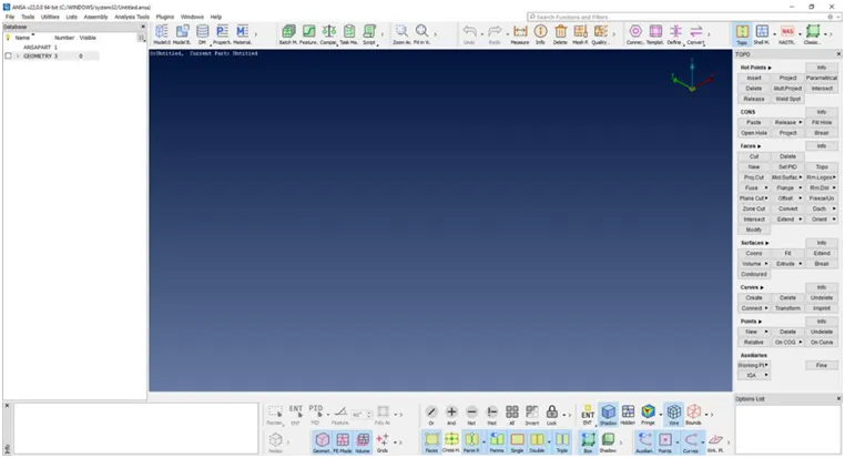
Fig : User interface
2. CFD(Computational Fluid Dynamics) :
2.1. Introduction :
- The CFD means we are analysing the behaviour of fluid on objects i.e. we are simulating the fluid properties like velocity, pressure, energy, drag force, continuity equation, momentum, thermal analysis etc.
Procedure :
1. Importing geometry:
- Open the ansa software then the dialog box come as shown in below figure and For CFD applications it is recommended that ANSA is started in CFD mode, by selecting the corresponding option from the launcher window. This will allow the better setup of the software interface for CFD pre-processing.
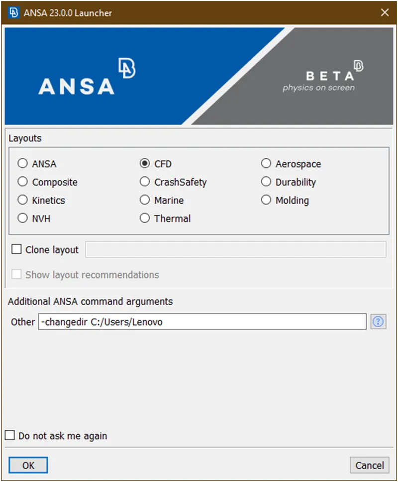
- At ansa command argument write ‘-performance_mode 3’ for smooth running the software in regular laptops/pc because to run the this software we required high configuration but our pc’s are not build to run these softwares as shown in below figure
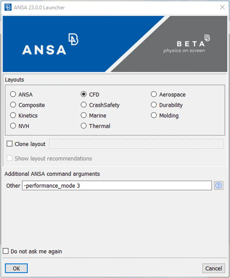
Then click on ok.
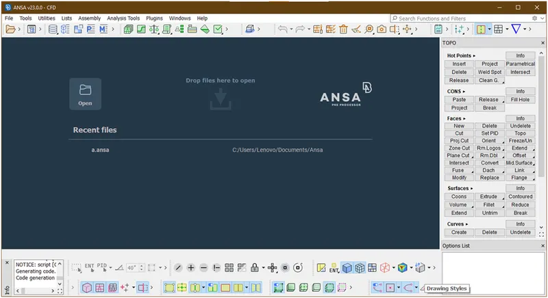
- Now the ansys user interface is open as shown in below figure.
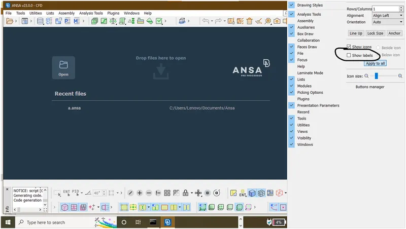
- Now ,right click on bottom menu then the dialog box is open as shown in below and find show lables and click on radio button.
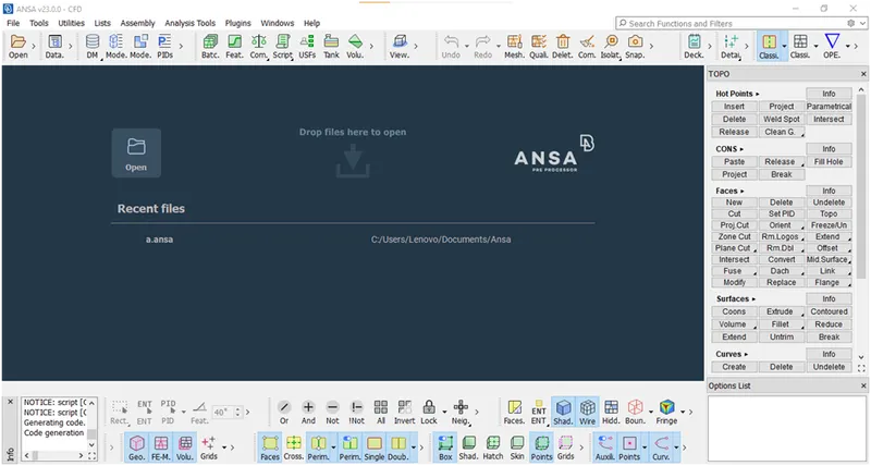
Now the lables will show as shown below figure.
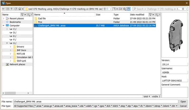
- Open the ansa file which is required here.
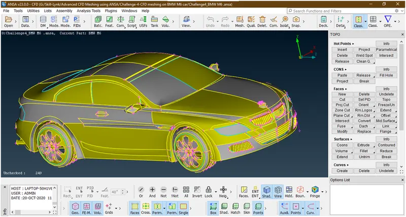
Now the geometry looks as
Now we are going for geometry cleanup.
2. Geometry Cleanup :
- By looking geometry the resolution is not in good way. so lets change the resolution.
- Goto the classic mesh-> perimeter-> length. A new popup opens as shown below.
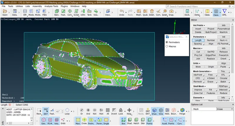
Then select perimeter and box select the geometry and hit the middle click.then new popup opens
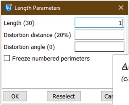
Then give length=1 and click on ok.the resolution has been changed.
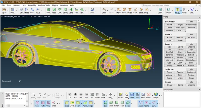
2. Lets apply topo to autofix some errors which are possible. For that goto topo mode-> faces-> topo-> box selection of geometry
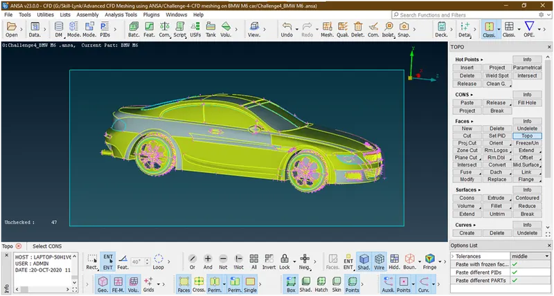
Then hit the middle click.now the some errors are fixed.
3. Now the car looks as
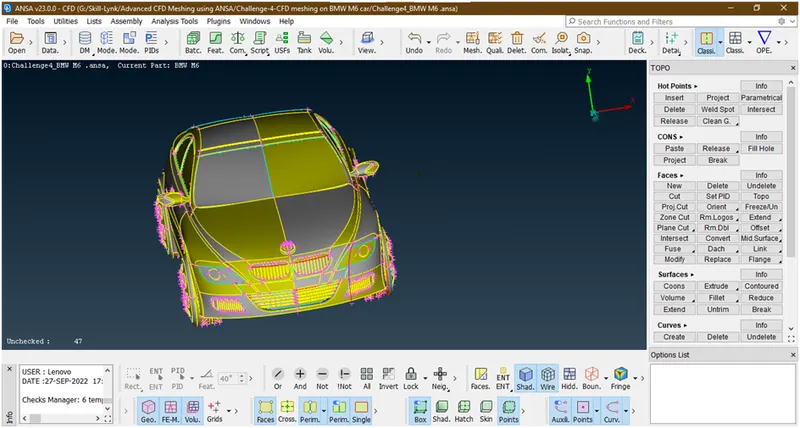
The geometry is symmetric about one axis so will first delete the half portion of car and work on this remaining half part and after that we will copy this part as symmetry and create the whole body.
- First we will hide the logo because its an unique by using not tool and pid mode of selection as shown below
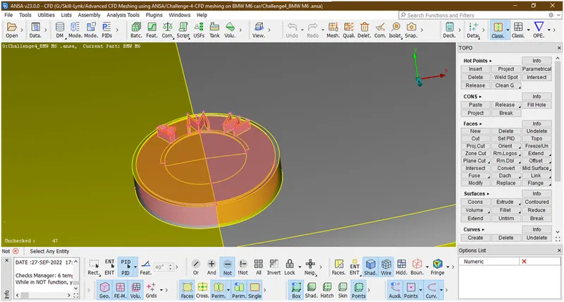
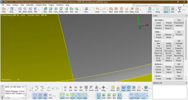
- Lets delete this half portion of a car.for that goto universal delete option and select the half portion of a car.
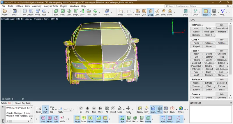
Now hit the middle click of mouse the new popup opens
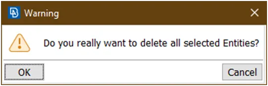
Click on ok.
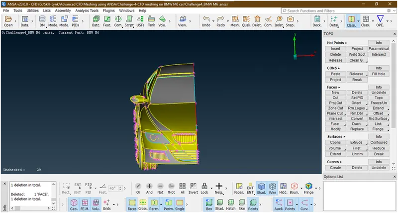
Now it has been deleted.
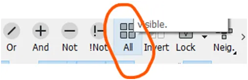
Now click on all so that logo will come.
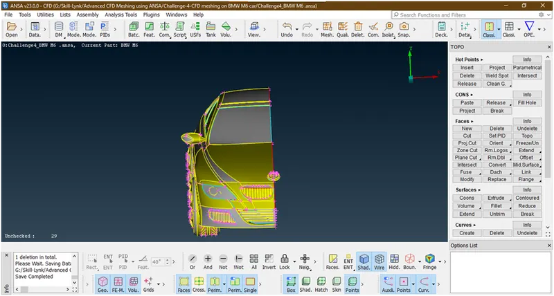
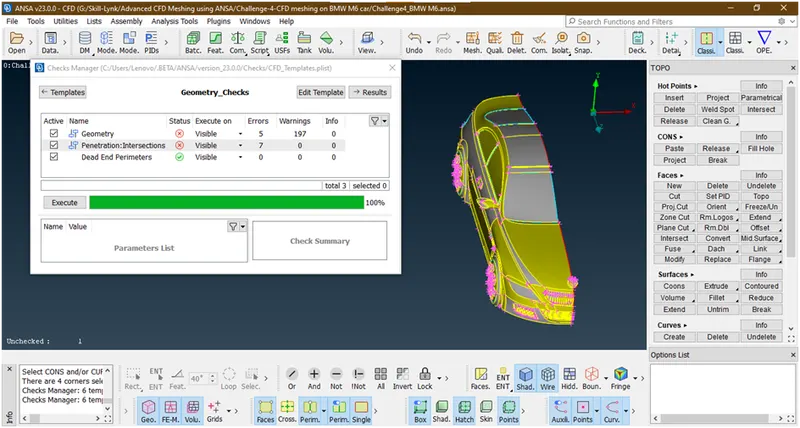
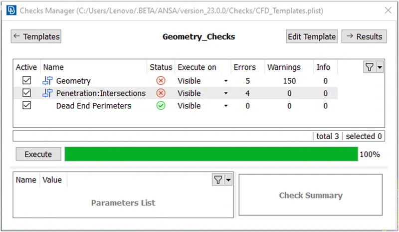
4. Lets check the errors in the geometry.
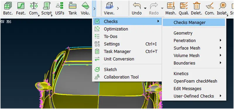
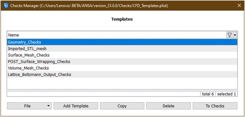
Double click on this then a new popup opens
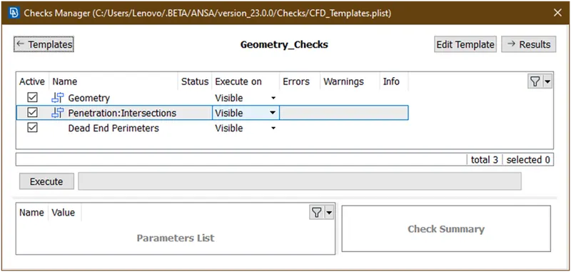
Click on execute.
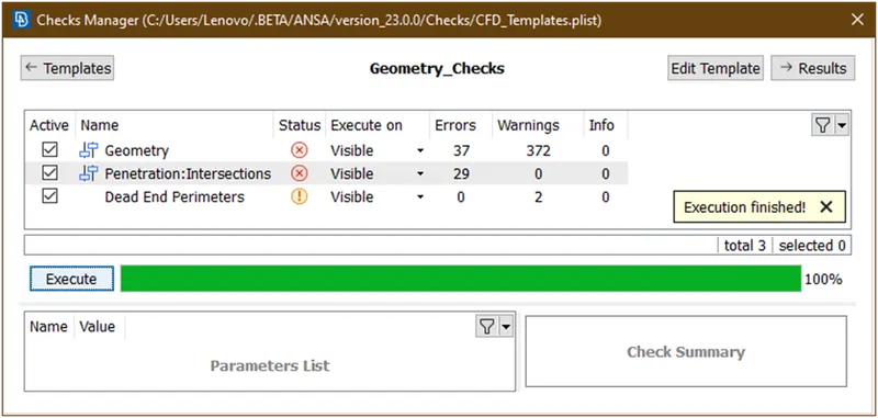
Lets see which are they
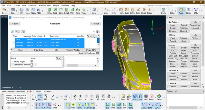
- Lets see geometry
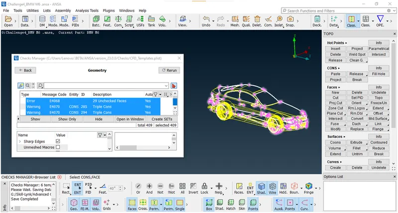
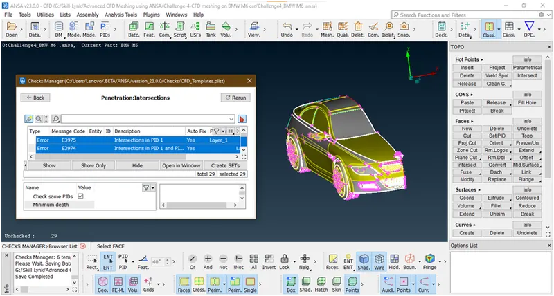
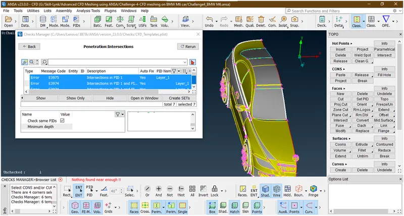
- Now we will see intersection errors
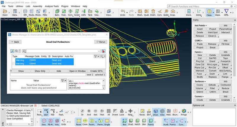
- And last see dead end error
5. First clear this grill part
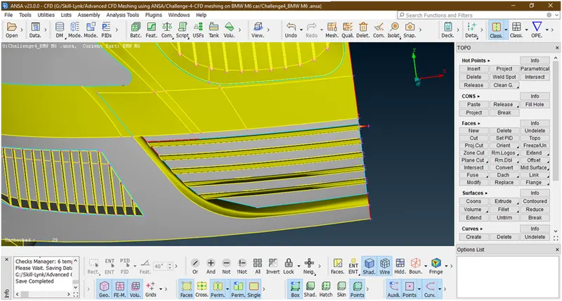
- Lets hide all part by using not tool with pentity selection mode and lock this

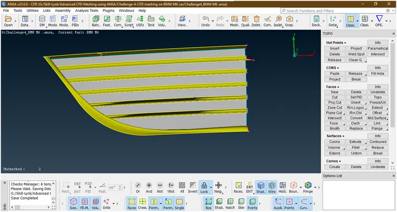
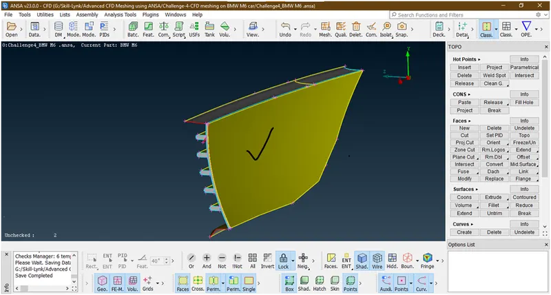
Now we are going for external flow analysis so we want a single volume that’s why we are deleting this surface as well as thickness and making it into single volume.
- To delete this surface we are using delete tool under faces and entity selection mode.
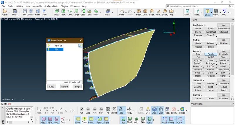
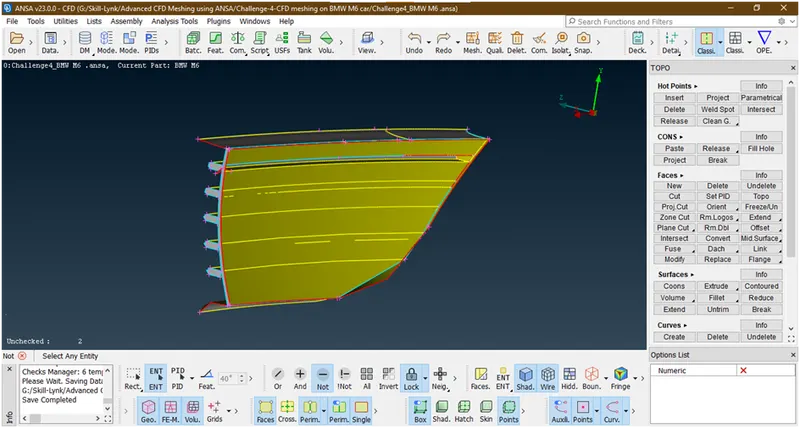
Now delete the thickness
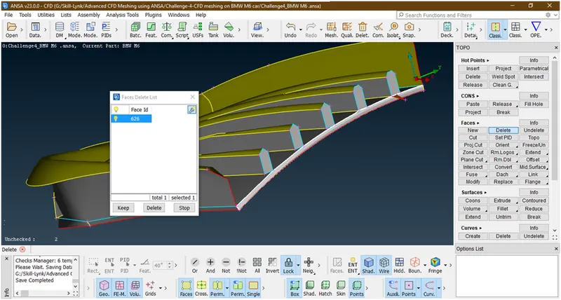
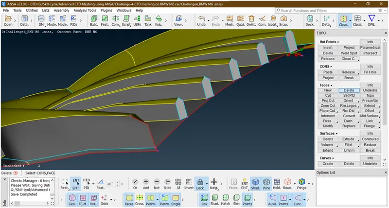
Similarly we are deleting side thickness.
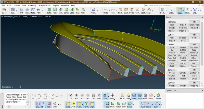
- Now we are deleting fins front surface so that it will create a single volume.
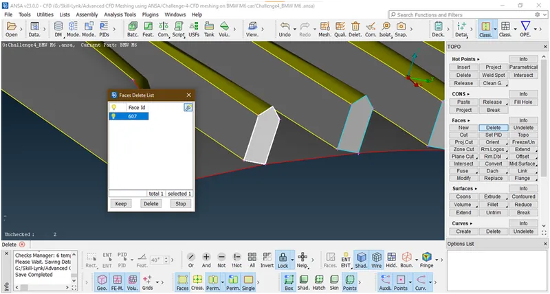
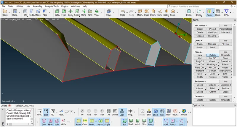
Similarly we are doing for other fins also.
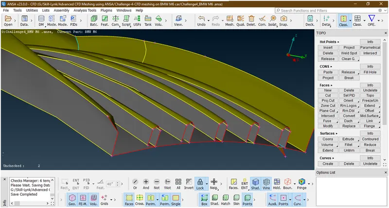
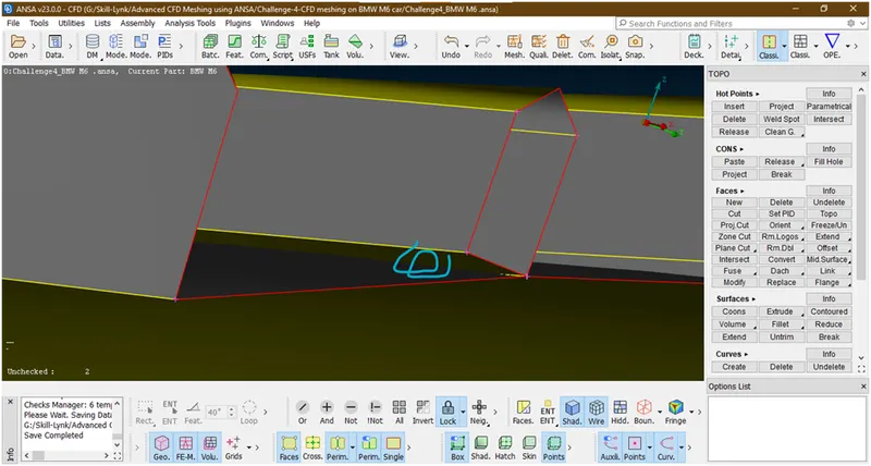
As we are looking to geometry this surface is not connected to the below surface so we are projecting this con.for that goto cons-> project
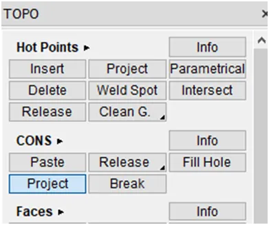
Now select the cons
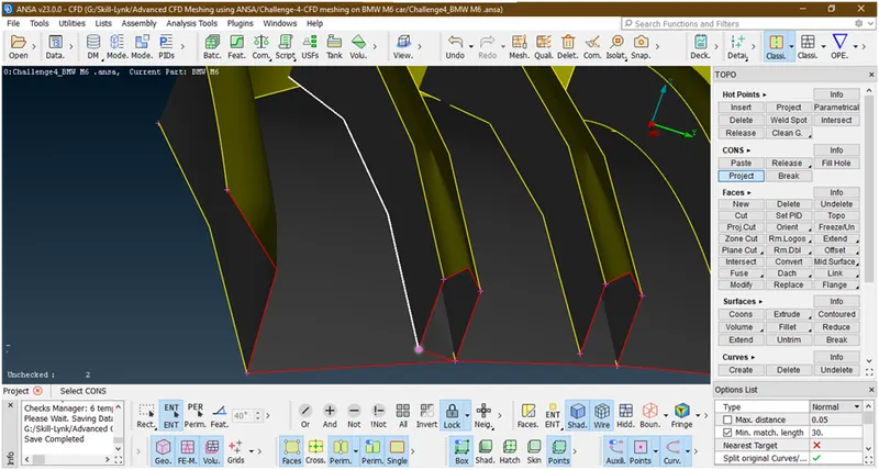
Now hit the middle click then its asked for to select the face then select the face
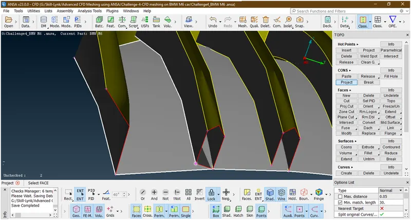
Now it has selected then hit the middle click then it will be projected
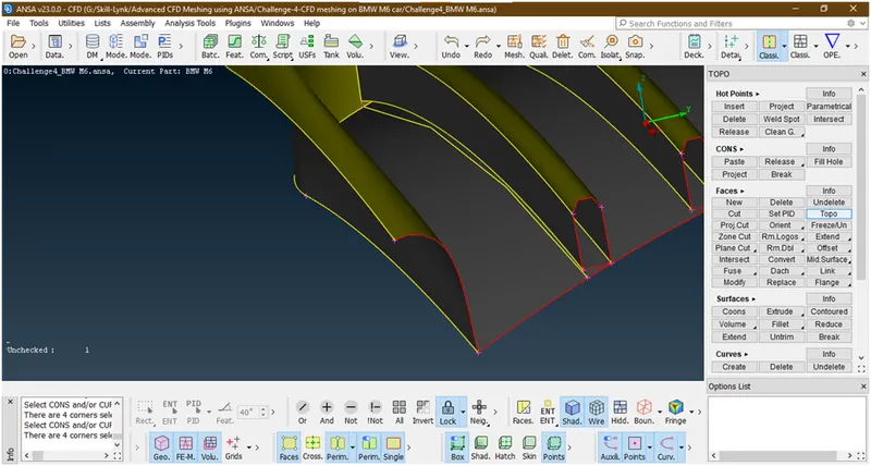
Now it has been projected let delete this face
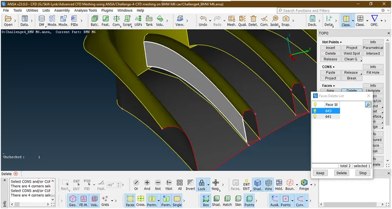
Also delete this face
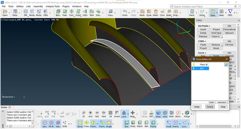
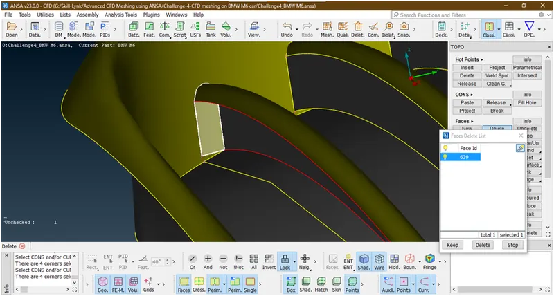
This will also delete.
- Let see the projection of con is properly touches to back surface or not
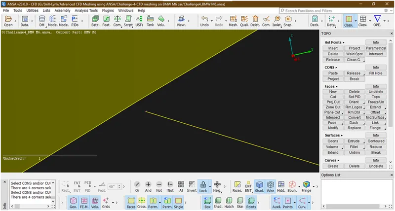
Now this is not properly connected.so we are extending this con to the back surface by using cut tool under faces
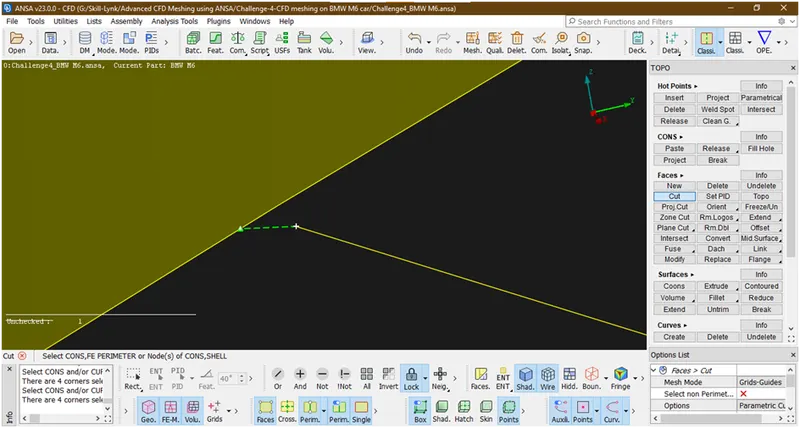
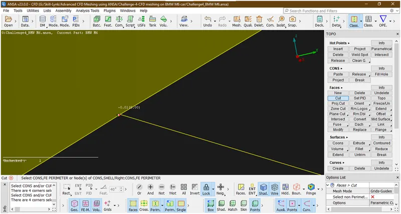
Now it has been connected.
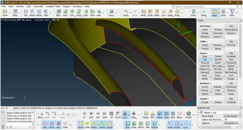
Now it does not look proper curve so we will change the resolution of this con
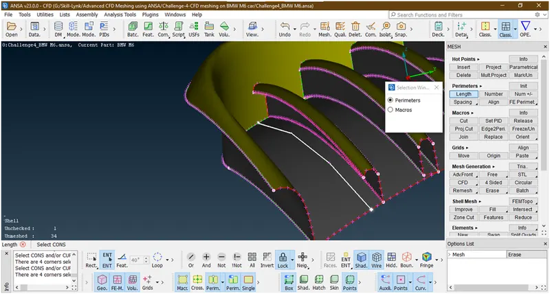
Hit the middle click then anew popup opens
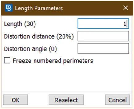
Give length=1 and click on ok
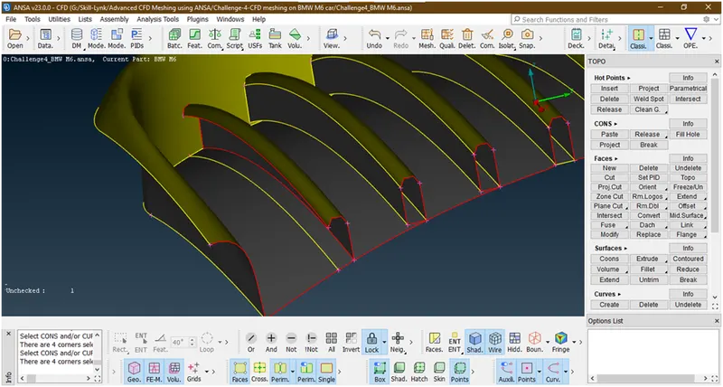
Now the resolution has been change.
- Lets create the surface there by using coons
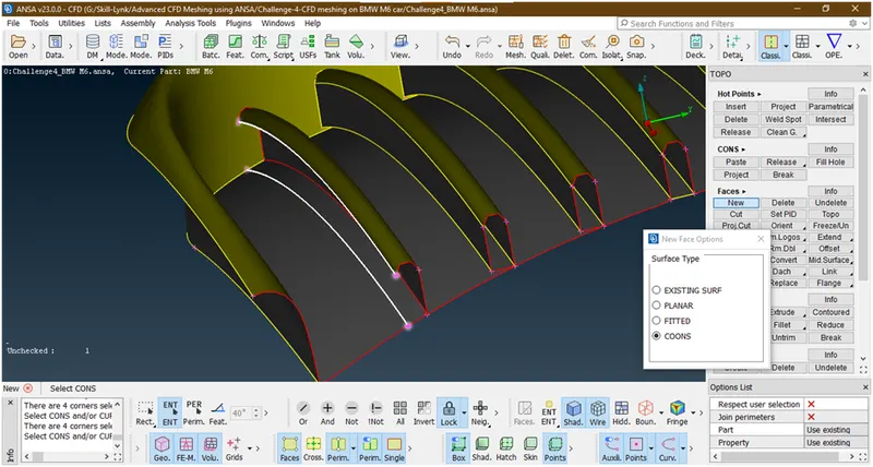
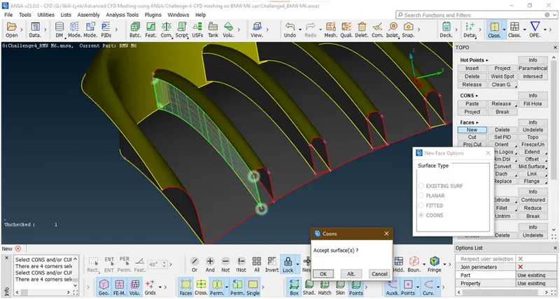
Hit the middle click then a new popup opens
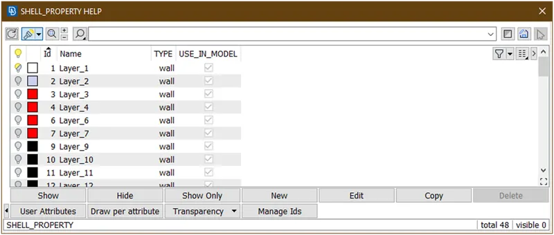
Now doble click on layer-1
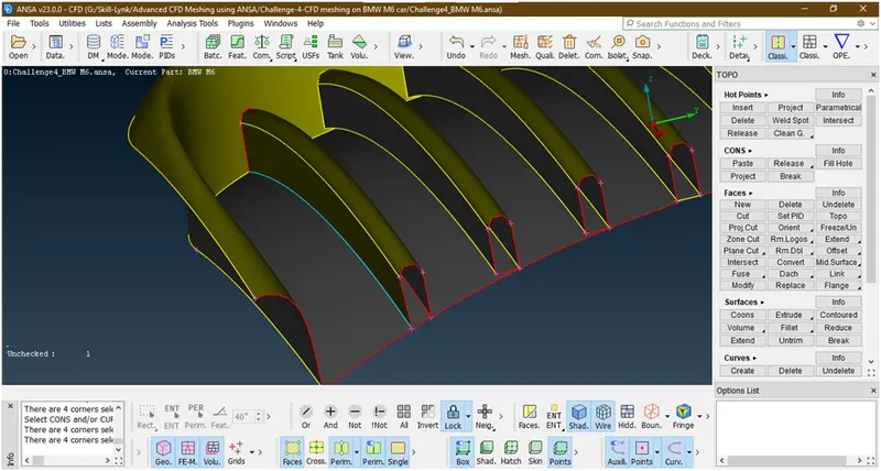
Now it has been created.
- Now project the other side cone to bottom surface.
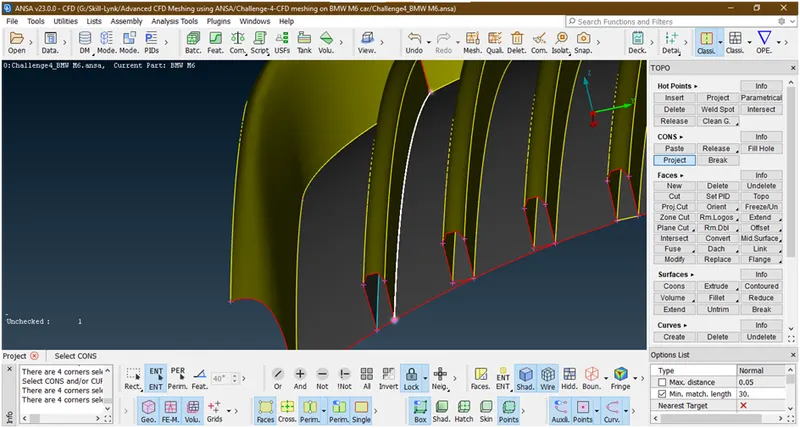
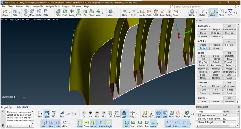
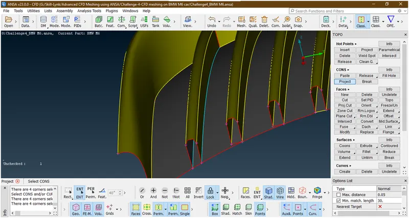
Now it has been projected.
- Now project these cons to back surface
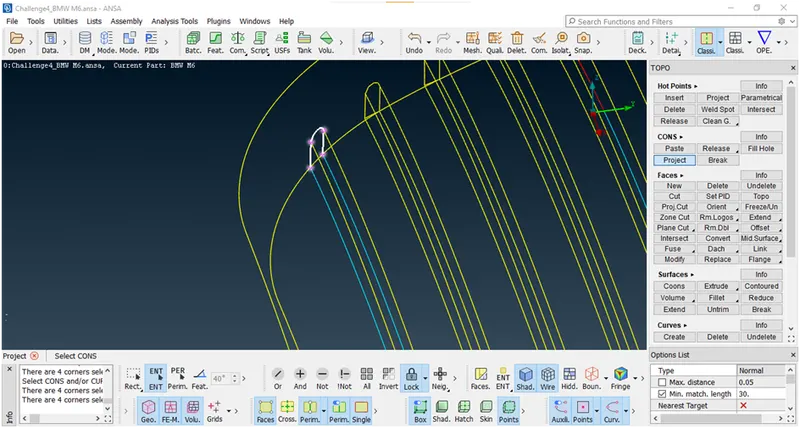
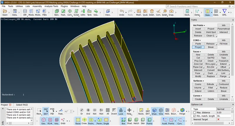
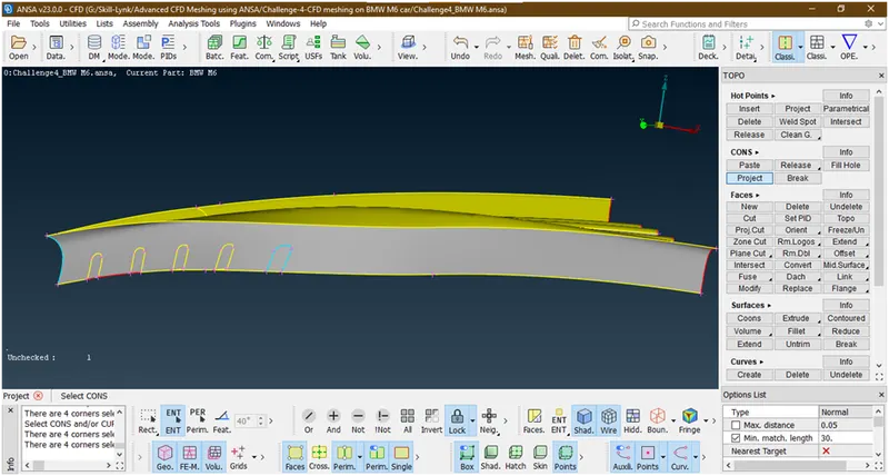
Now its projected.
- Now delete this faces because we want a single volume so we are creating these surfaces
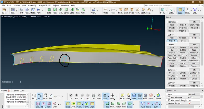
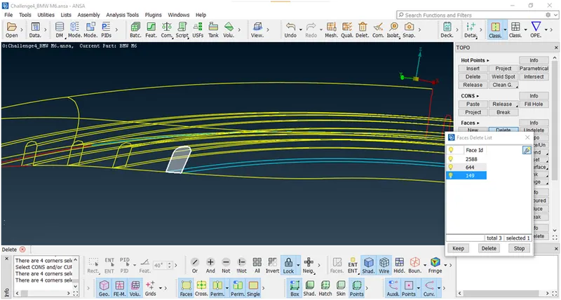
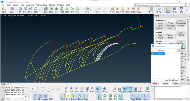
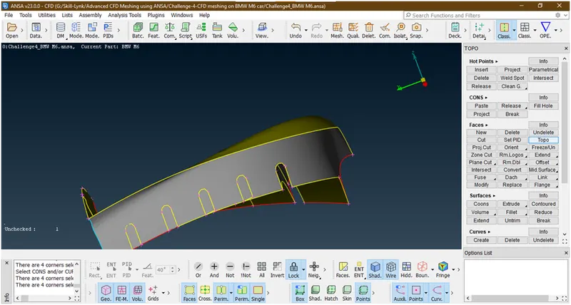
- Similarly we are doing for all fins. The final geometry looks like
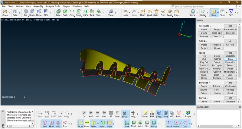
Now we have created this single entity grill.
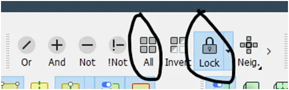
- Now remove the lock and click on all
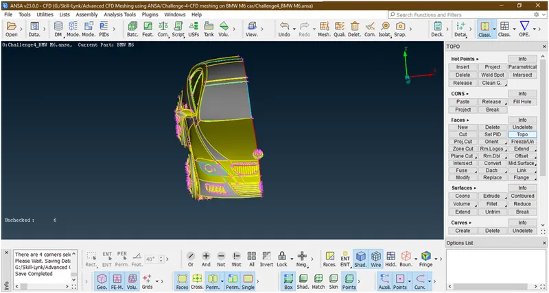
Now we are going for next part.
6. Now we are going for next grill to clear geometry. Now hide the other part and concentrate on this grill. To hide all other parts we use not tool and lock this geometry.
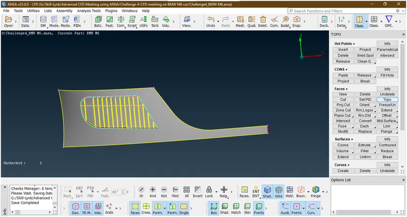
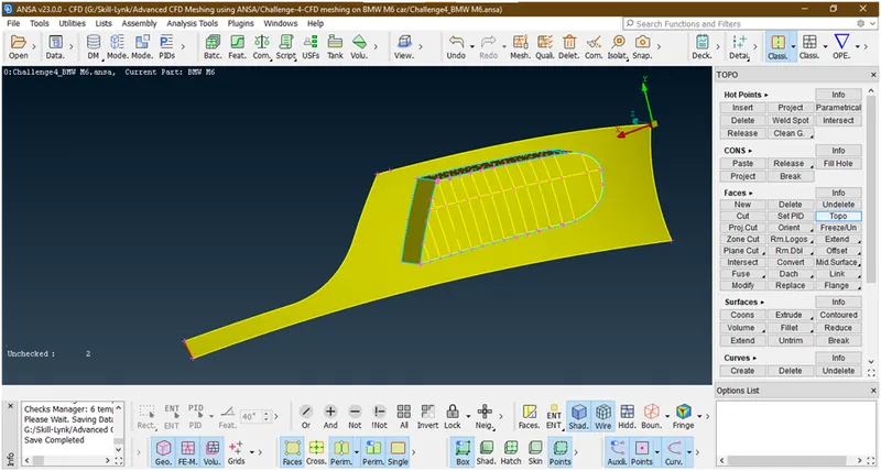
- Let check errors in this grill
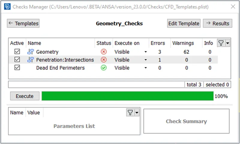
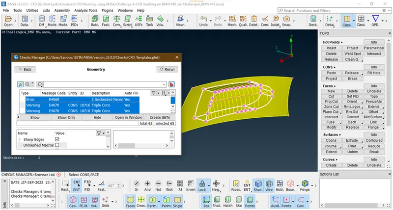
Let check geometry errors
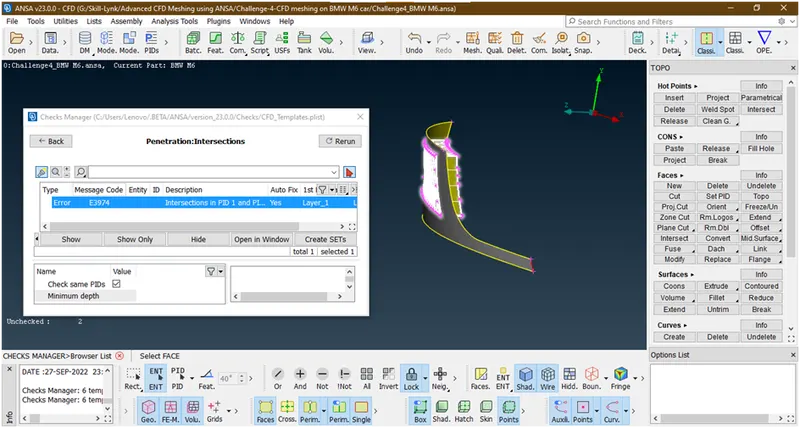
Let check intersection error
- Let hit topo
- Now let see inside the grill why errors are occurred.
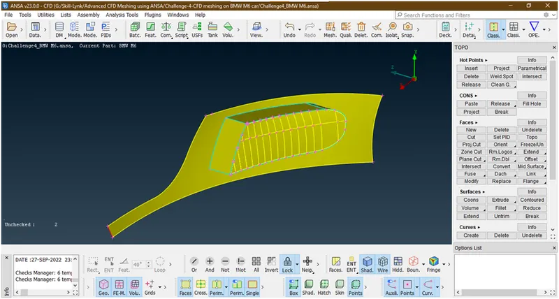
Let hide this surfaces and look in to it
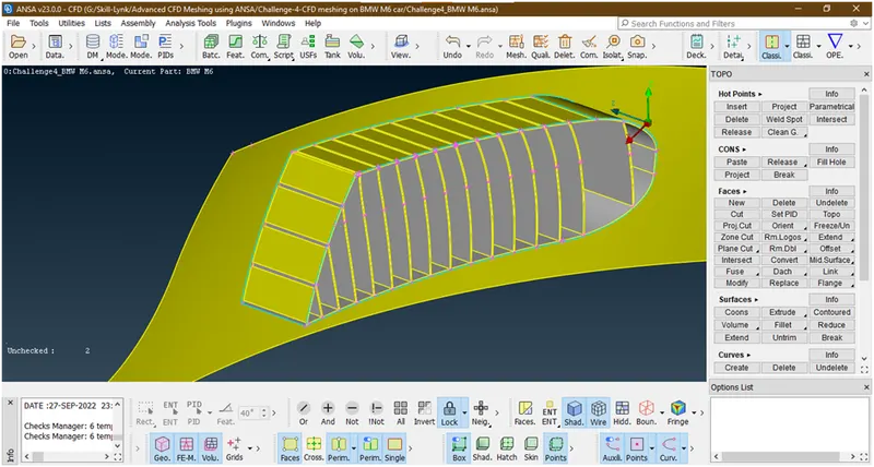
Let zoom out and see
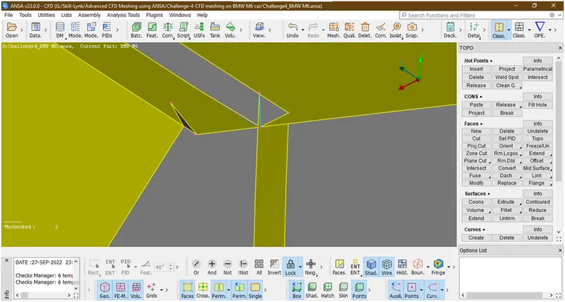
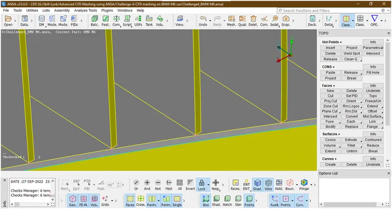
By seeing this geometry there is some distortion .so let clear this. For that we will create a surface at 20% distance from back surface and by doing intersect we will delete and some thickness of grill from inside and this will not affect to the our analysis because we are going for external flow analysis and making a single volume entity.
- Let click on all
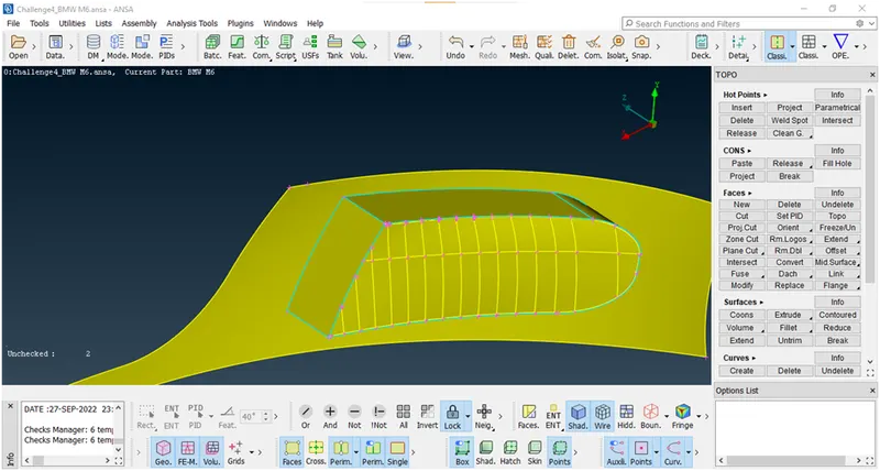
Let create an hot point using parametric length as shown below.
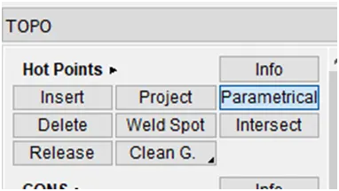
A new popup opens
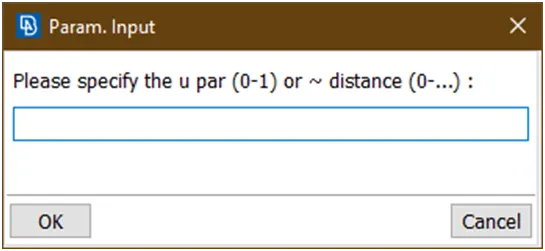
Now select the con and give value as 0.2
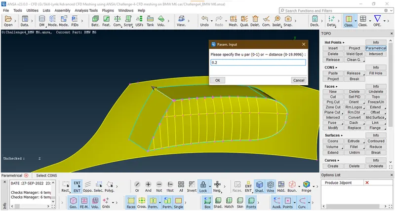
Now select the right arrow direction and click on ok.
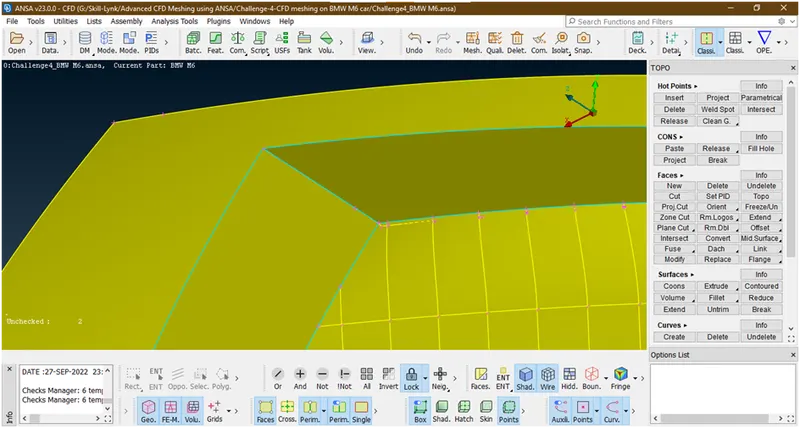
Similarly we are inserting a hot point around this grill.
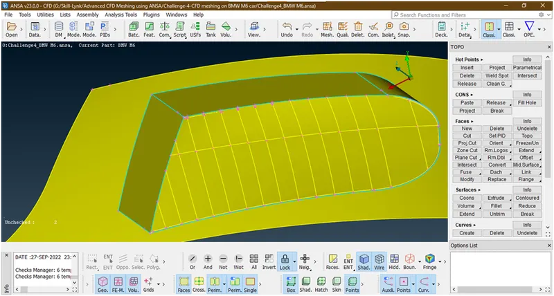
Now create a cut through this hot points.
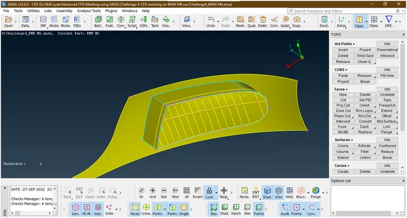
Now crate a surface through these cuts for that goto faces->new->coons and select loop as selection mode and then select coons
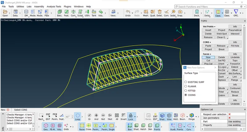
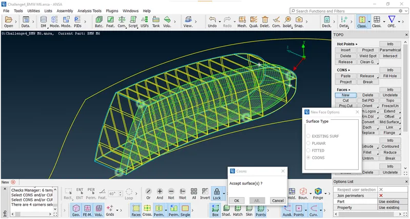
Click on ok a new popup opens
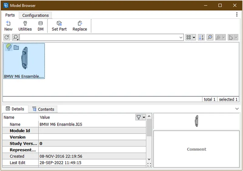
Double click on this again a new popup opens
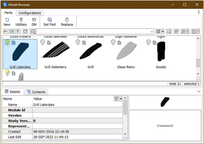
Click on this grill then again a new popup opens

Then double click on this layer 1 then new surface create.
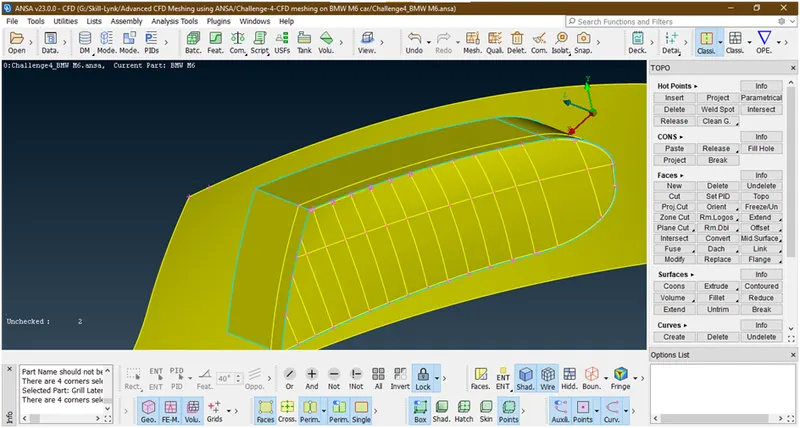
Let hit an topo
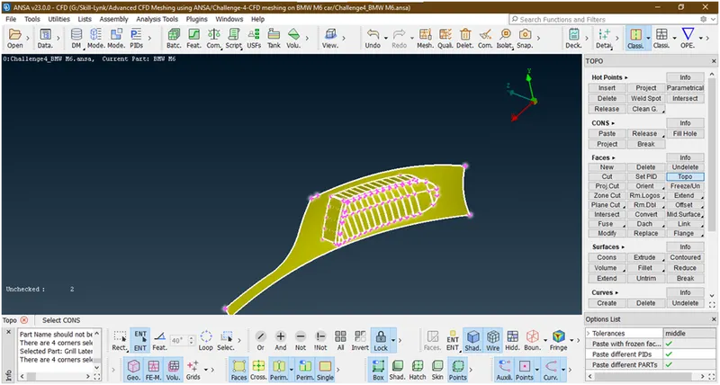
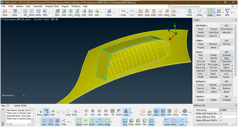
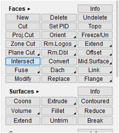
- Lets goto intersection for deleting the unwanted surfaces
Now select the 1st surface
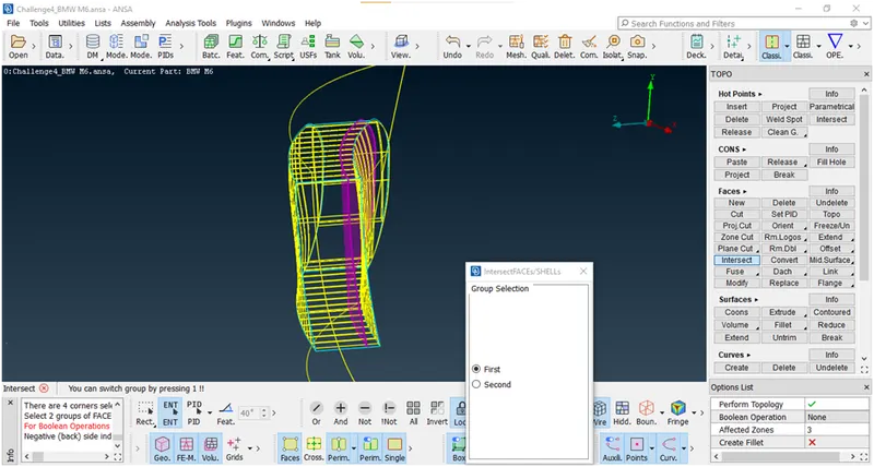
Now hit the middle click.then it asked for 2nd faces so box select all the grill
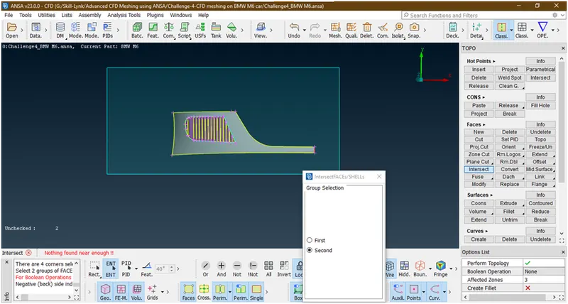
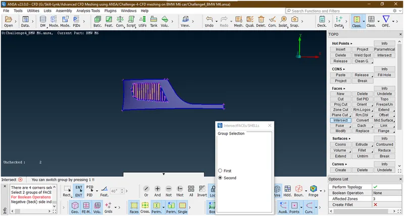
Now hit the middle click then it asked for which surfaces are want to delete and which surface want to keep
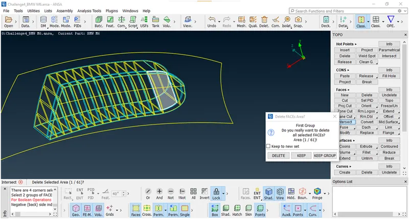
Now this surface we nedd so we will keep it.Similarly asked for 61 faces then we will do same procedure.now the final geometry looks like after doing all delete and keep operation
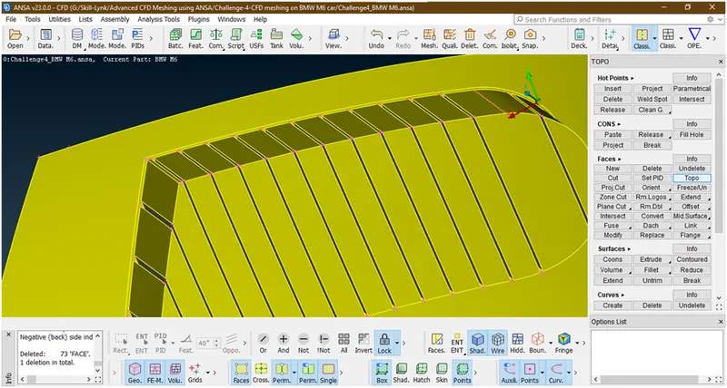
Now we have done the uniform thickness.
Now lets check for errors
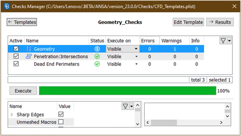
Let check for warning
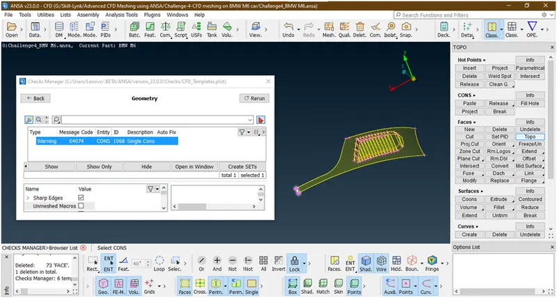
Now this is the single con warning due to we have deleted half portion of car.so we are neglecting this.
- Now remove the lock and click on all
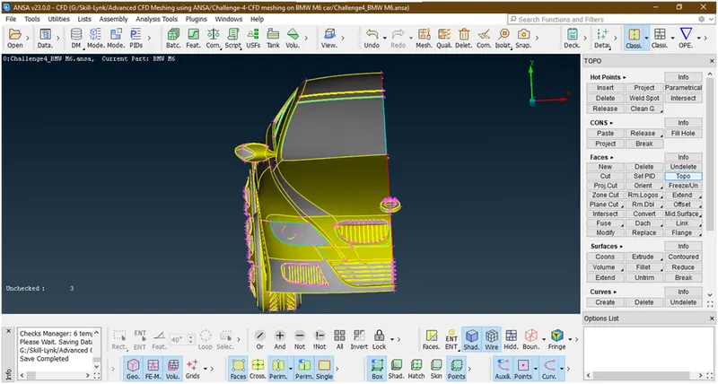
Now let check for errors which are remaining.
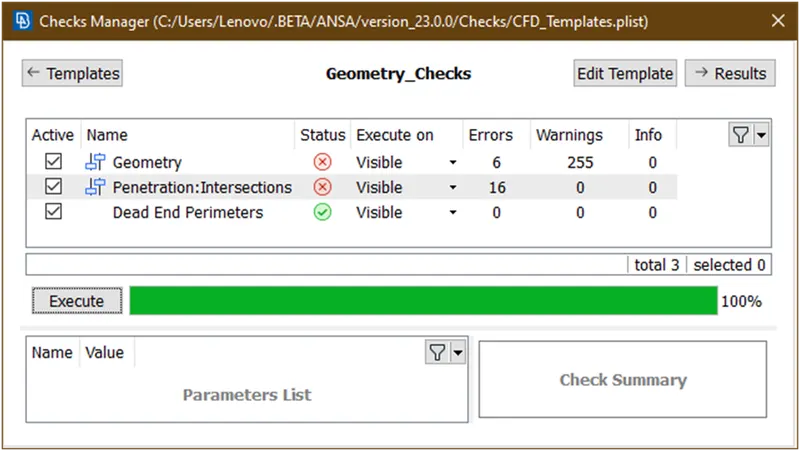
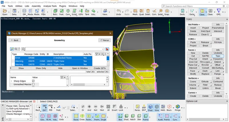
Let check for geometry errors
Now let check for intersection error
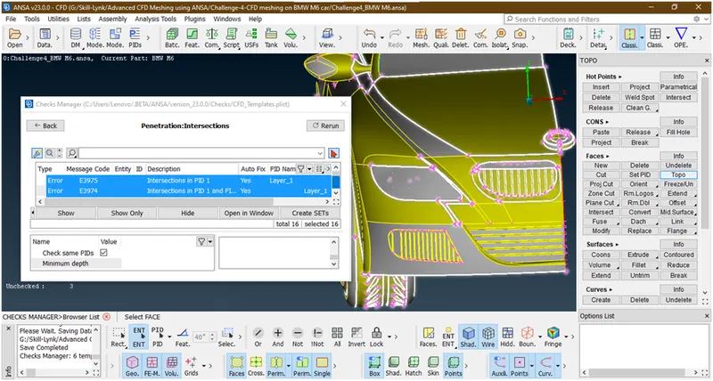
now lets go for clear the errors in next grill.
7. Now we are concentrating on this grill by hiding all other parts using not tool
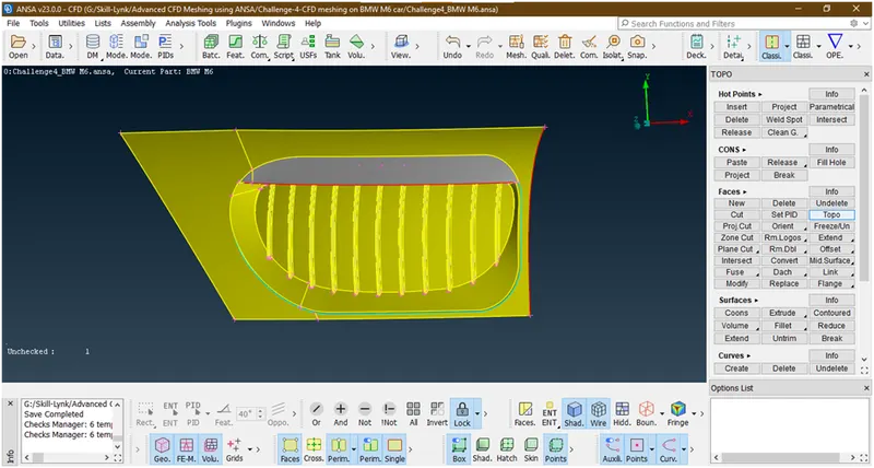
Now we have hided all other parts and we done locked the geometry.
- Let see check the errors in this part
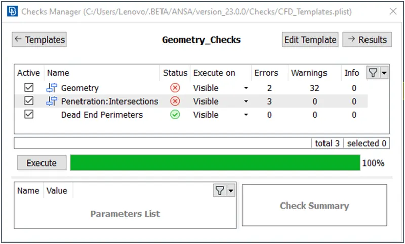
Let see which are they
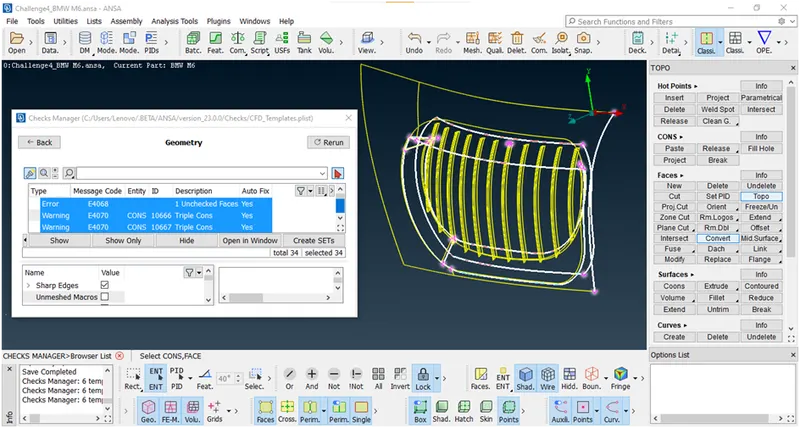
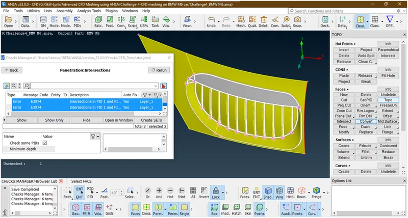
First lets clear this geometrical errors.
- Click on not and lets hide this surface and see why triple cons are come
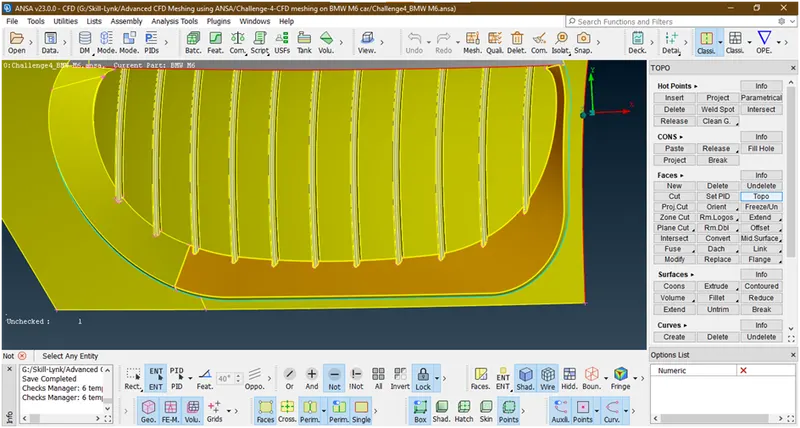
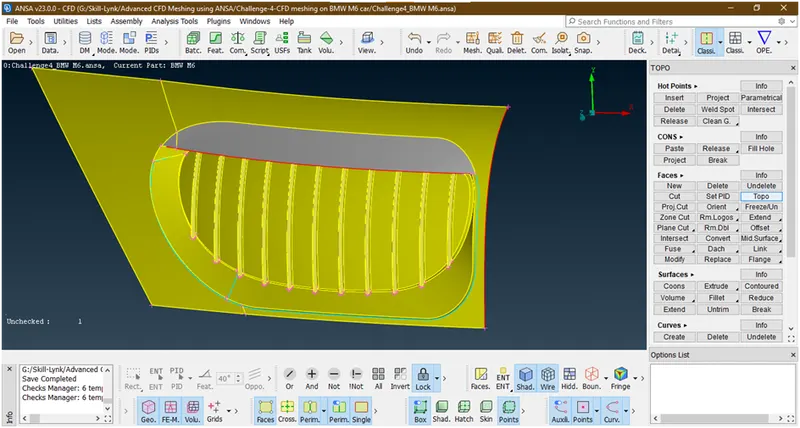
Now this is because of some overlapping surfaces. Lets click on all and delete these surfaces by using delete tool under faces.
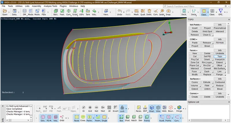
Delete this back surface because we want a single volume entity as we are going for external flow analysis.
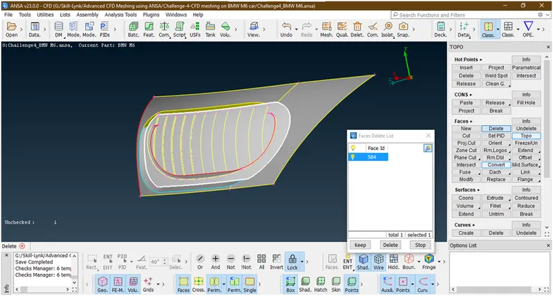
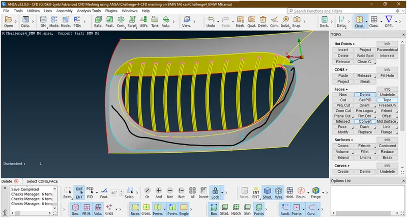
We have deleted the back surface now lets delete this overlap surfaces.
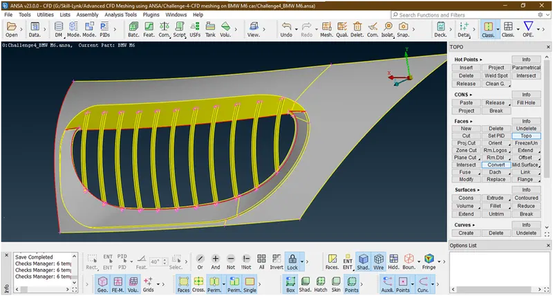
We have deleted these overlap surfaces.
- By closely looking to the geometry we have noticed that the fins are in distorted shape.
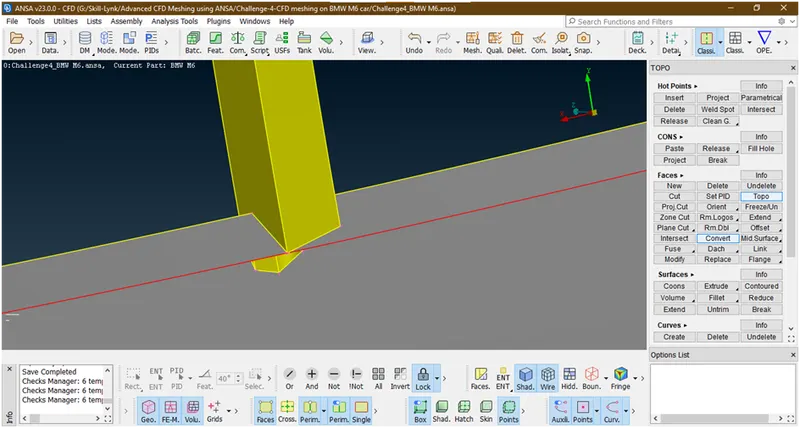
Lets align this. Before that we are deleting these back surfaces of a fins to make a single entity.
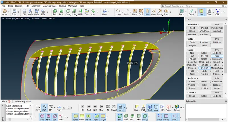
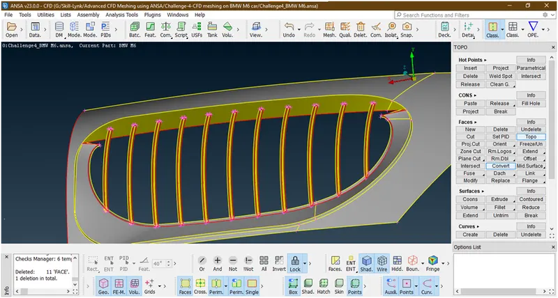
We have deleted this surfaces. Now we aligning this fins by using cut option under faces.
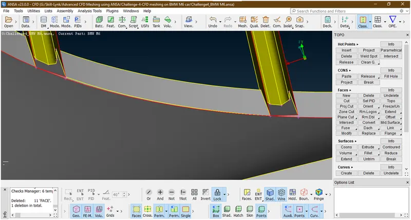
Similarly we re doing this and deleting this faces.
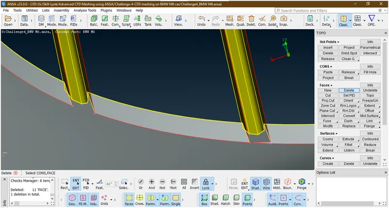
The similar procedure we are doing for all other fins.
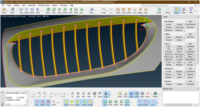
Lets create a surface there as shown below
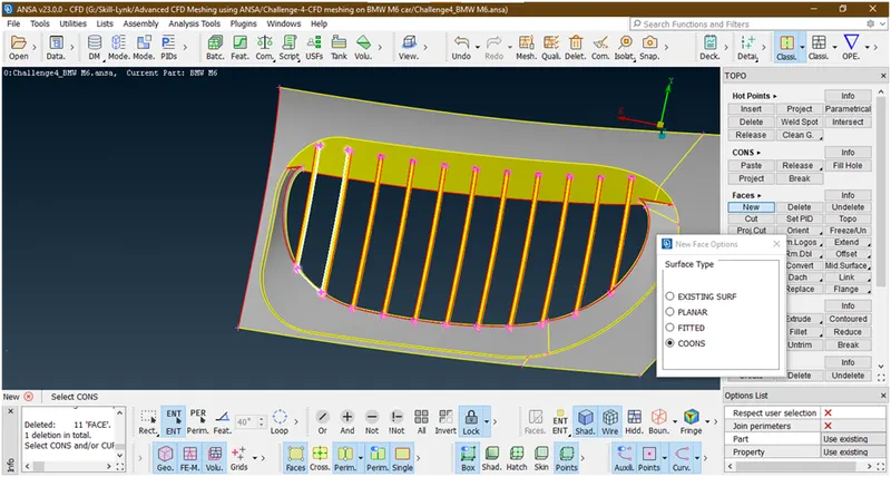
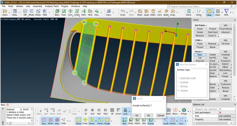
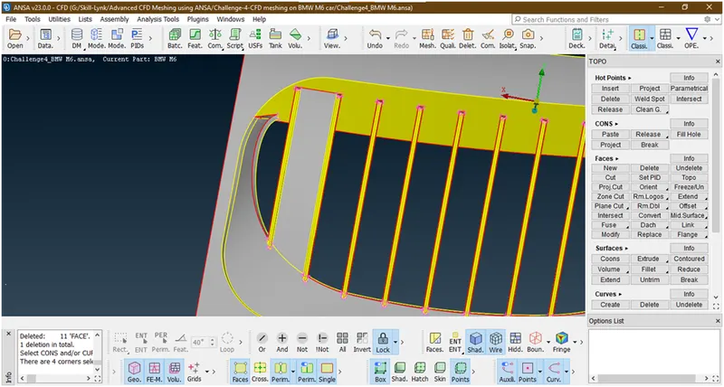
Similarly we are creating the surface in between the fins.
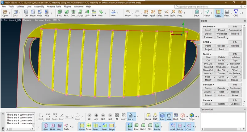
We have succefully created these surfaces. Now we will delete this upper portion of grill because we don’t need this as we are closing this with cap surface.
- Hide all other parts by using not tool.
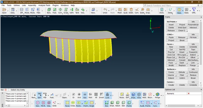
Now project this red con to behind surfaces and fins.for that create a hot point in between as shown
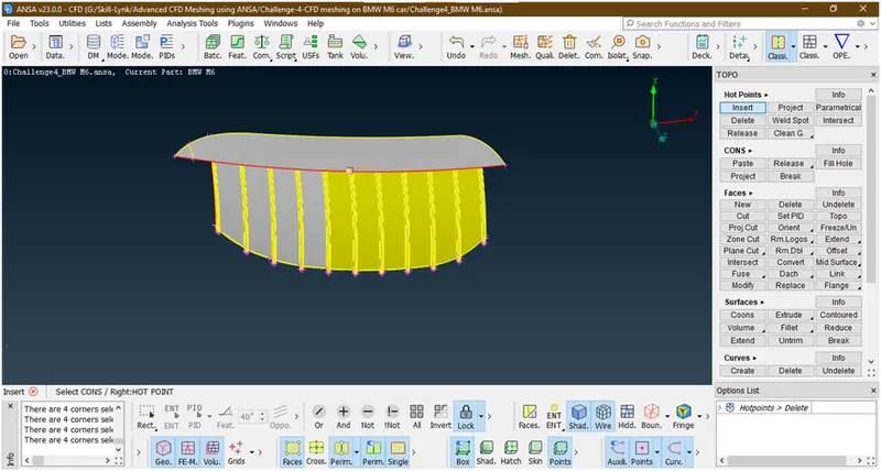
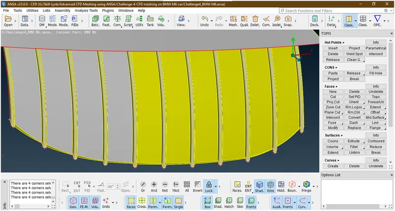
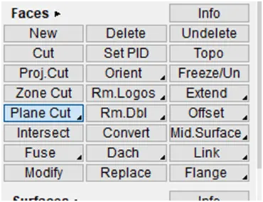
Now goto the plane cut under faces and select the hotpoints
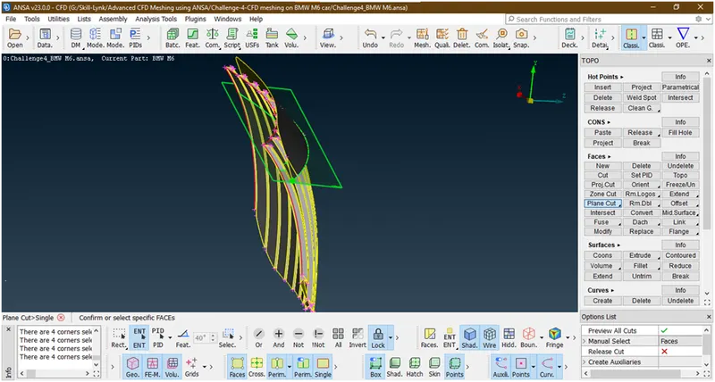
Now hit the middle click , then anew popup opens
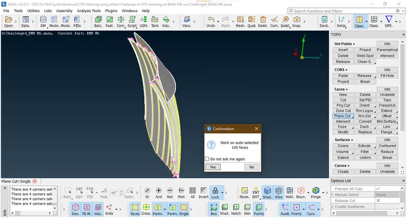
Click on ok
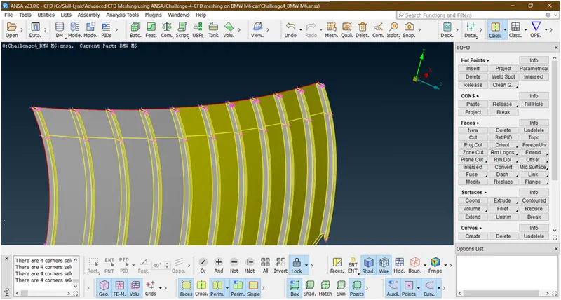
Now it has been projected. Now hide the all other parts which are required and delete the unwanted part by using universal delete tool
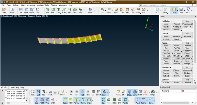
Now delete this and click on all
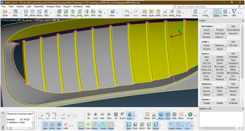
Now they have been deleted.
- First of all let see why intersection error occurred and where it is occurred.
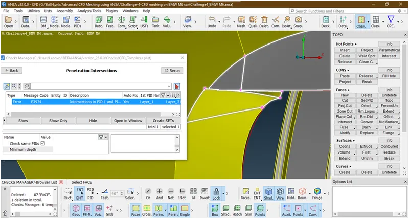
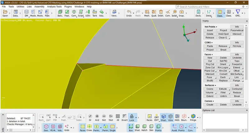
Now this is because of this surface is going into another surface.let try to delete this surface.
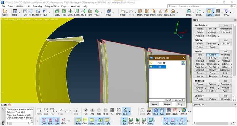
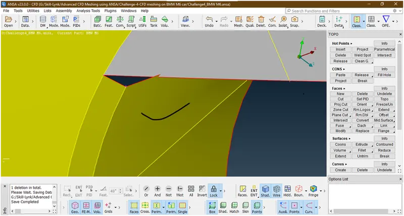
Also this surface making intersection with other so we will create an cut there and delete this part
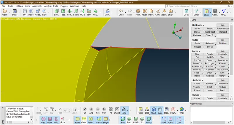
Now delete this
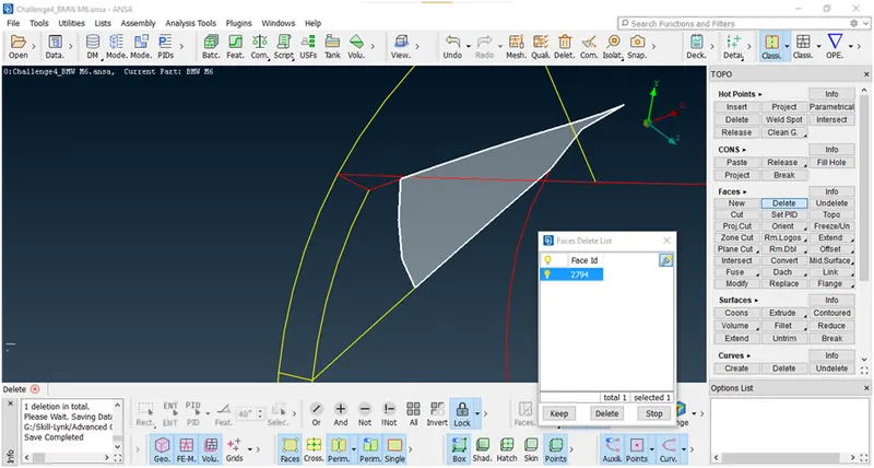
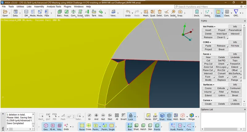
Now lets make a surface there
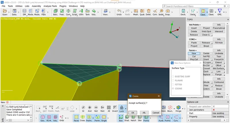
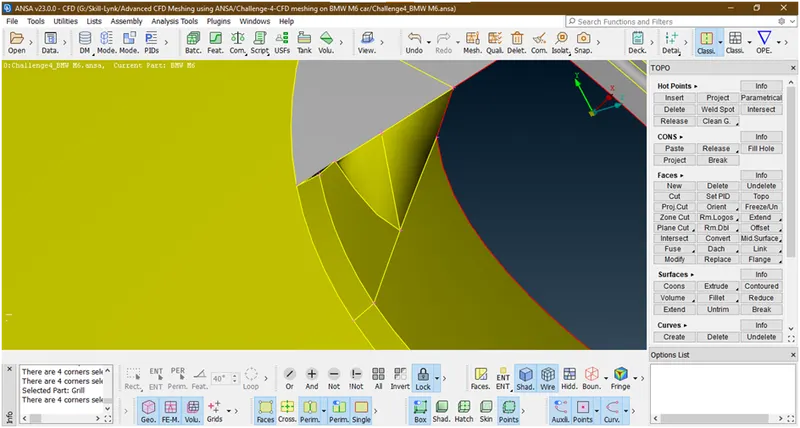
- Now lets fill this gap by making a surface.
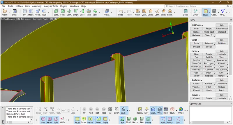
To create a surface there first project the hotpoints
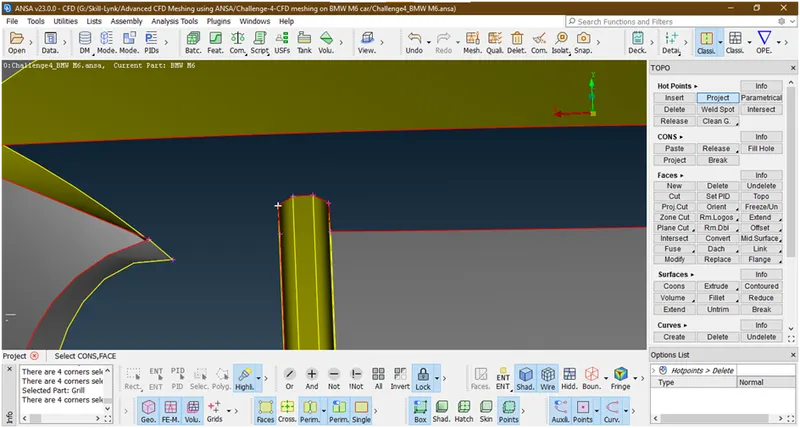
Now select the con
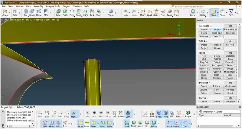
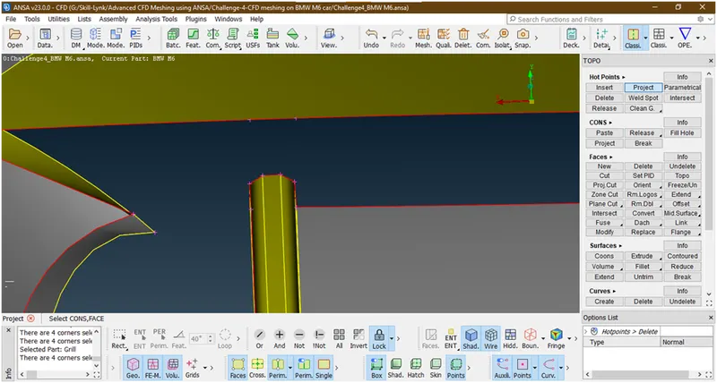
Now they have been projected. Simillarly project the hotpoints of other fins to this coon.
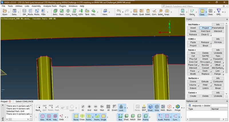
Now create the surface there
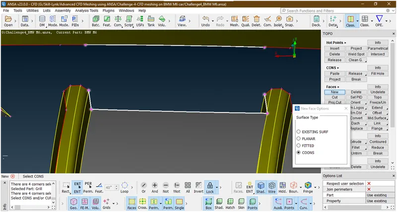
Hit the middle click
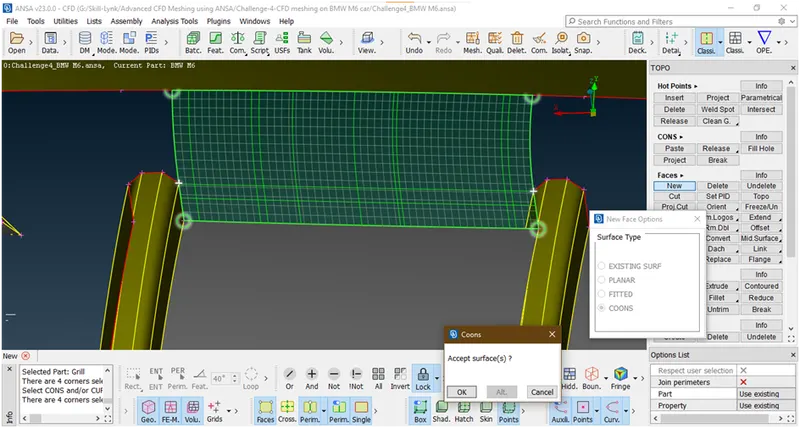
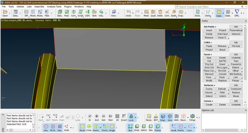
Now we are oing similar procedure to create a surface there
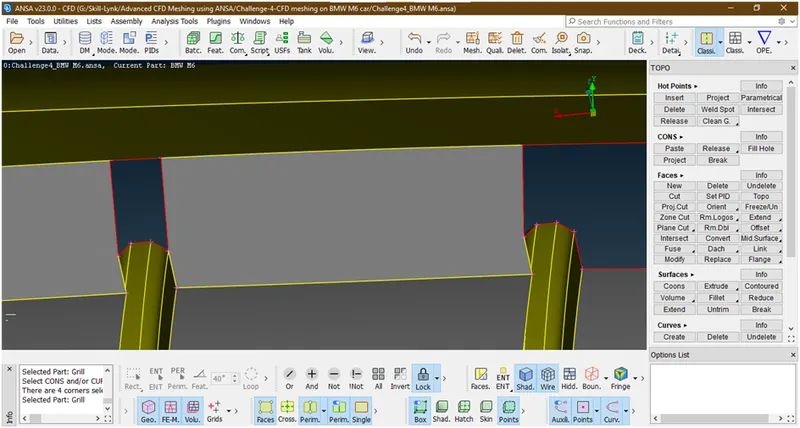
Now the hole which is looking there also we are creating the surfaces by using coons.
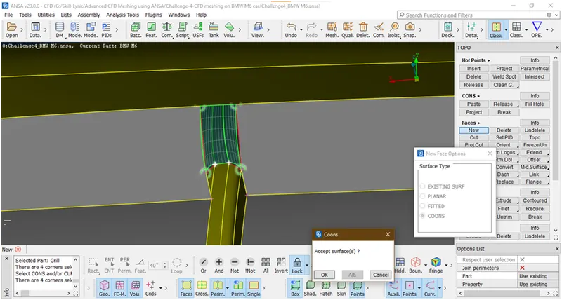
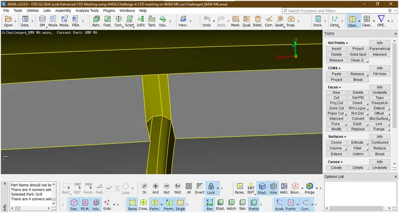
Similarly we are doing for all fins.the final geometry is
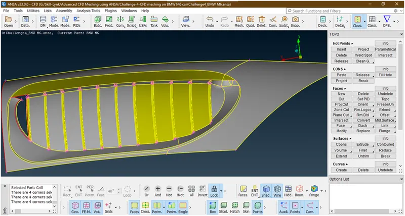
Now we have created the surfaces there. Now the open part is seeing we will go with similar method as there is a intersection error.
- Delete this face
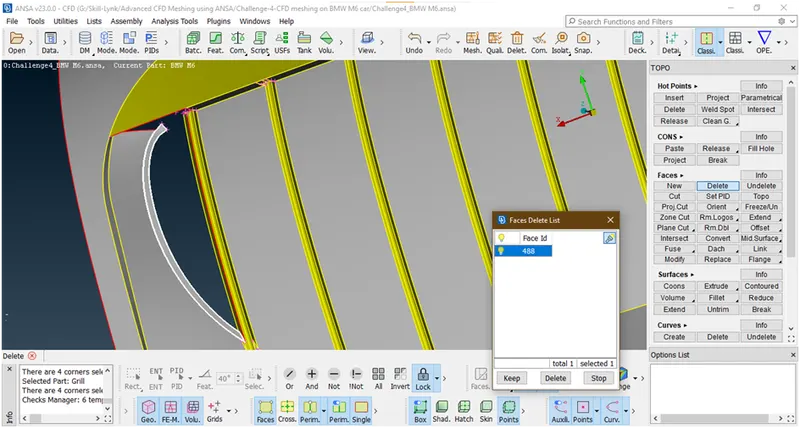
Now create a surface here
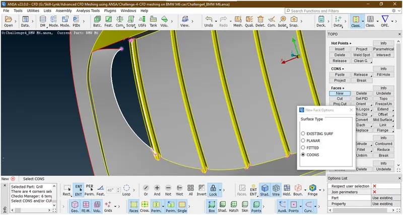
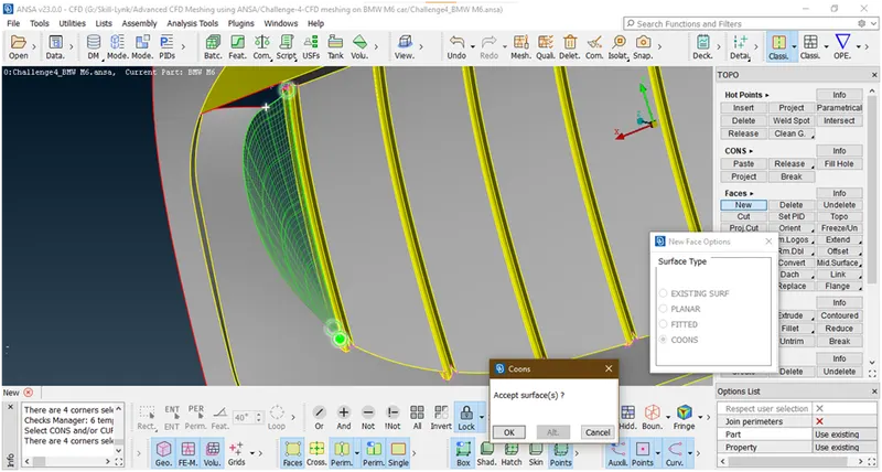
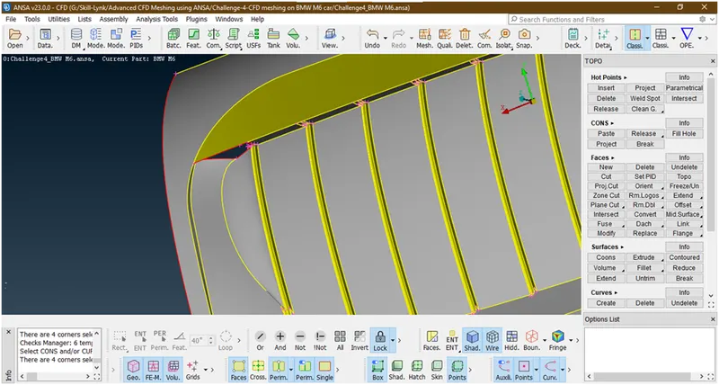
- Now insert a hot point here
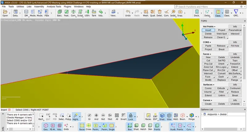
Now create a surface there
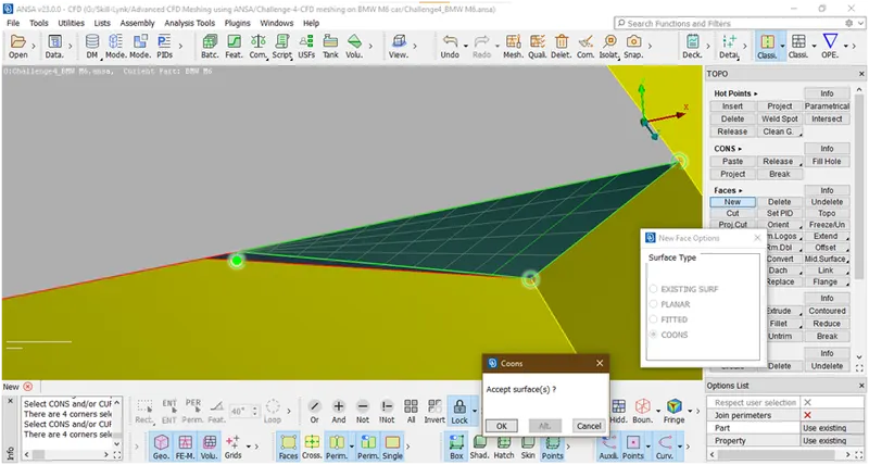
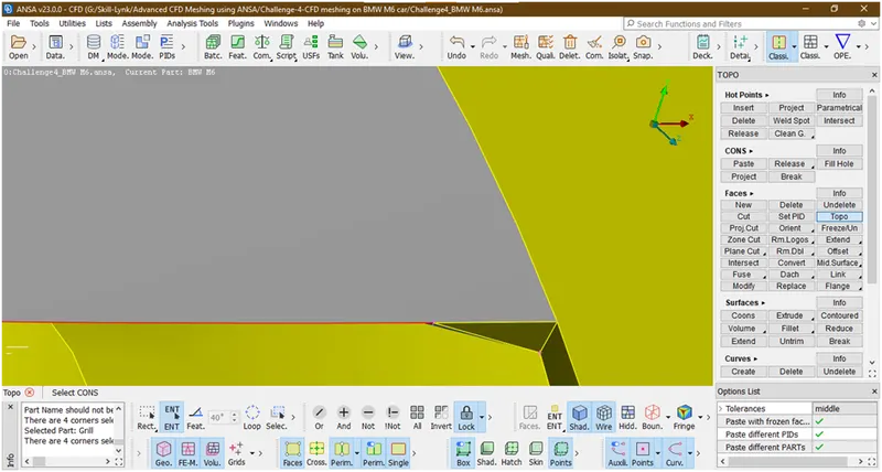
- Now create surfaces here
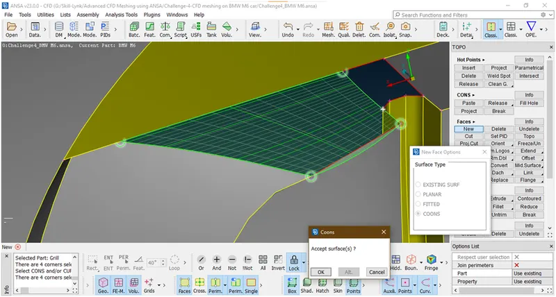
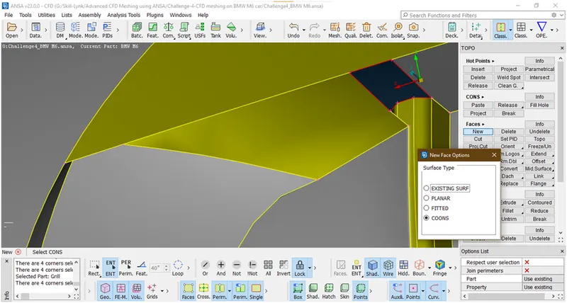
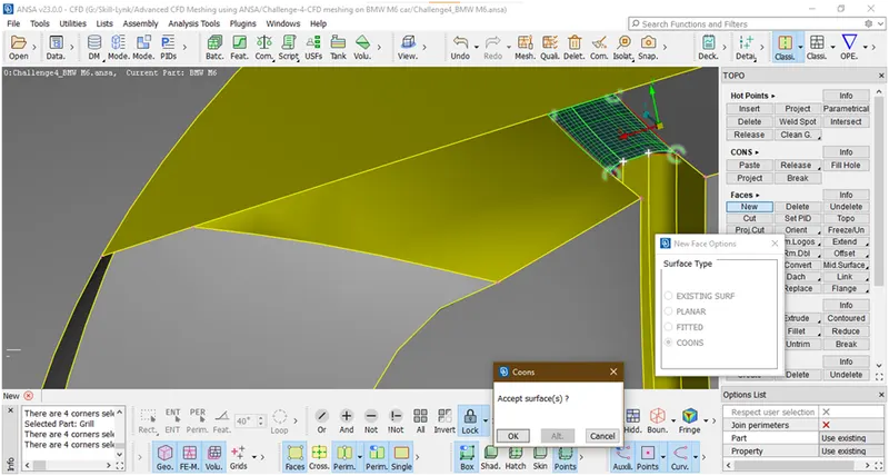
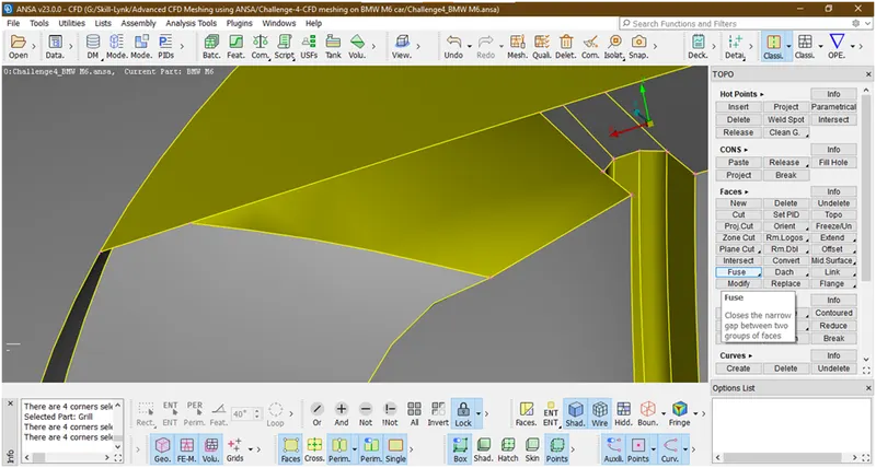
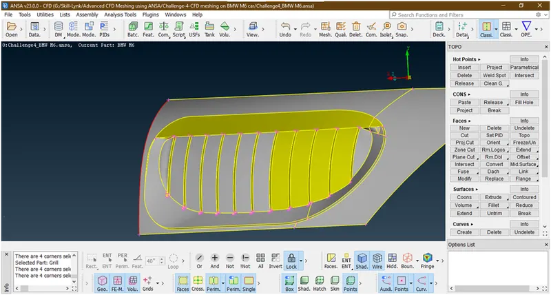
This is the final geometry.
- Let check for any errors are remaining.
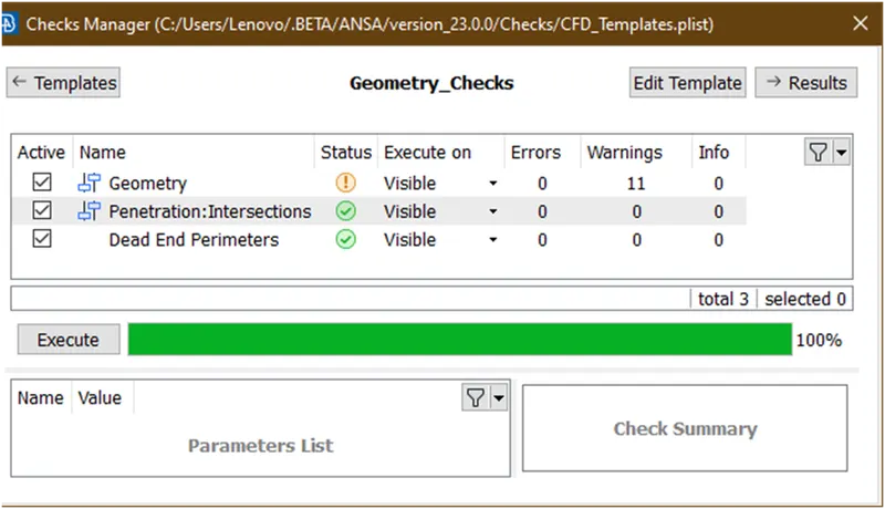
Let check what are the warnings for geometry
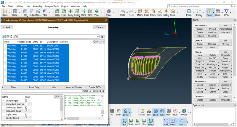
These are the mixed coons,concave coons,convex coons which are ignore bacause this comes due to shape of geometry. So we have successfully removed all errors in this grill.
- Now lets remove the lock and click on all
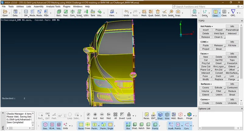
Now we are going for next part.
8. Now lets goto the lights and see why this triple cons come
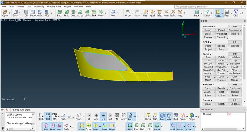
Now this is closely packed so we are not worry about what is inside.
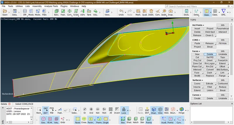
So we are deleting this inside part because we are going for external flow analysis and for that we want a single volume so we are deleting all things which are inside.
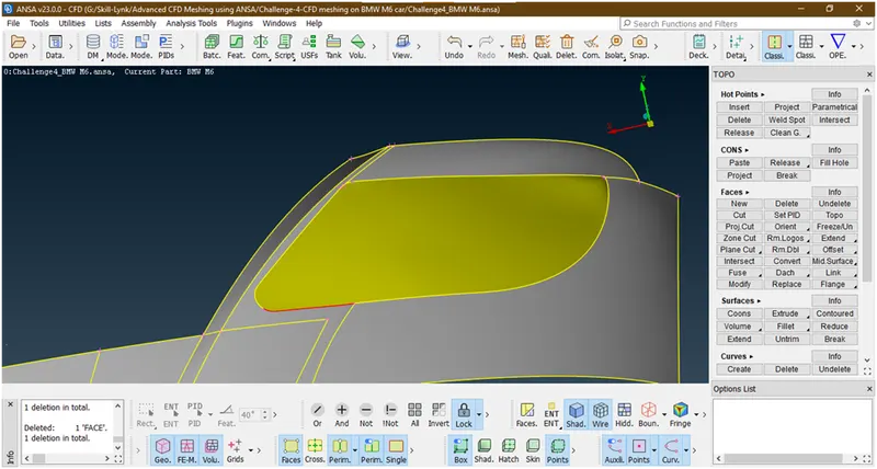
Now we have deleted the all parts of lights.now we are seeing some red con.let see why this occurred.
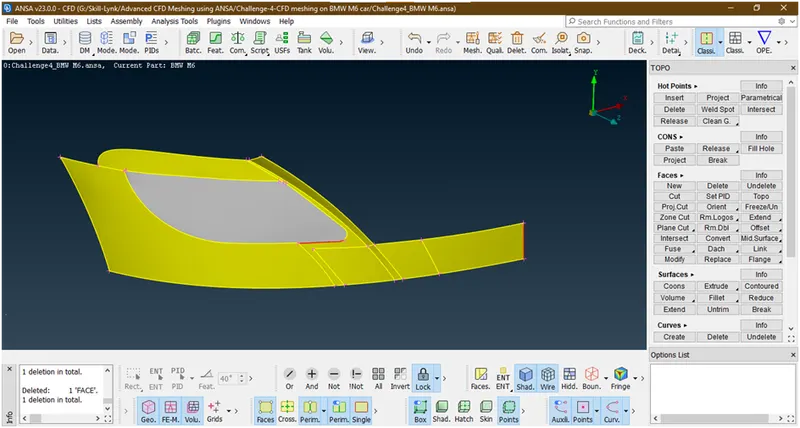
We have succefuly removed all triple cons.
Let check by check manager
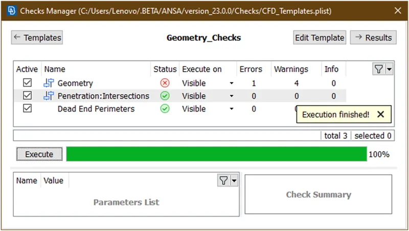
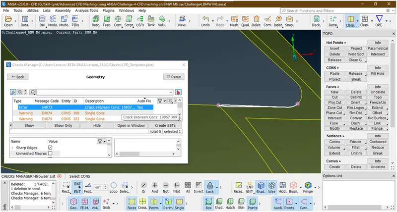
Now this is the crack let filled this crack now this can be done by creating a surface there
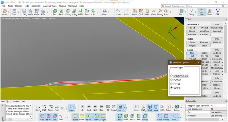
Now hit the middle click
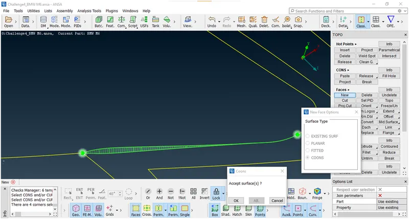
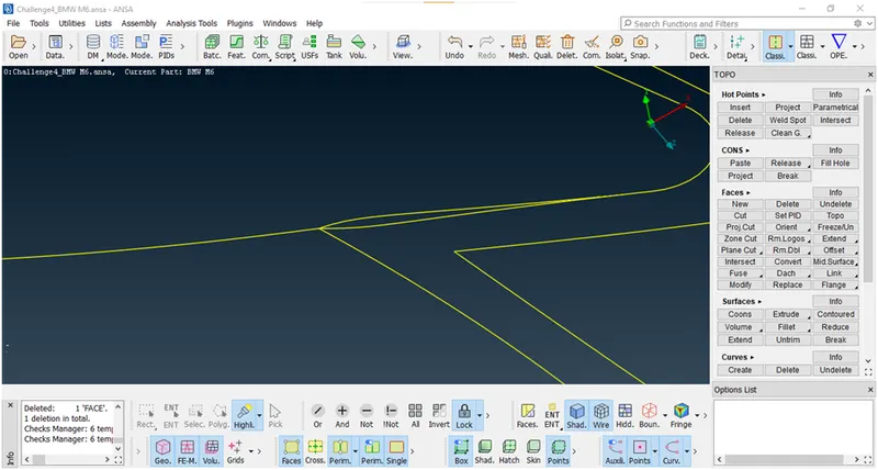
Now it has been created.now again check for eny errors are remaining
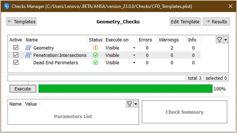
Now let see which are the warnigs are
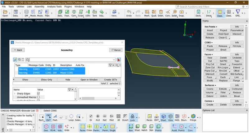
These are mixed cons due to shape of geometry so ignore it.
- Now remove the lock click on all
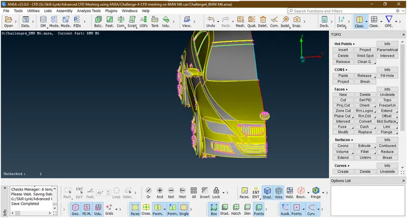
- Lets check errors
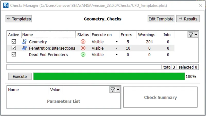
Now let see where are they
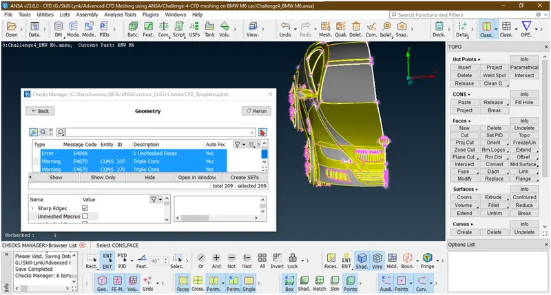
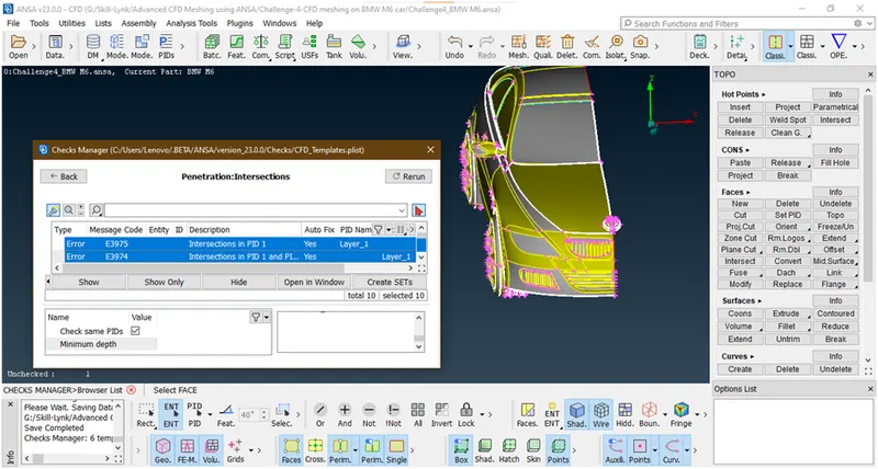
Now lets go for next error.
9. Now we are going to clear logo
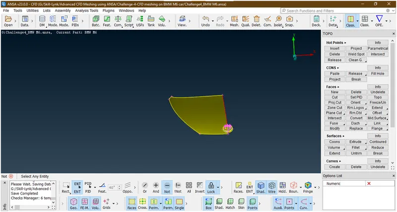
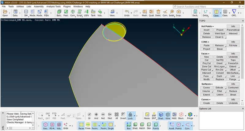
Now at bottom face we are seeing sme triple cons lets hide this and see why this come.
- Lets check for errors
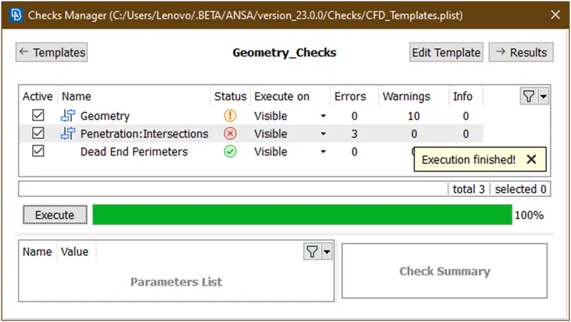
Lets see which are they and where it is
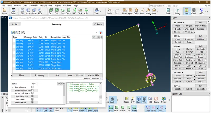
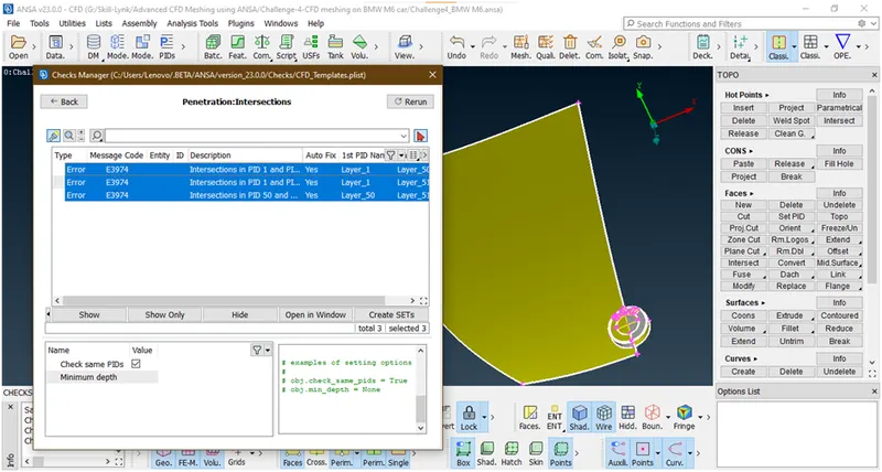
- Let try try to remove triple cons
Now hide this face
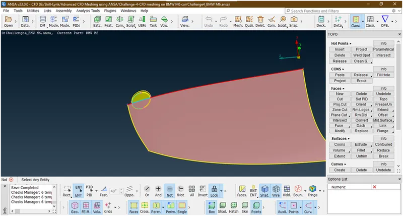
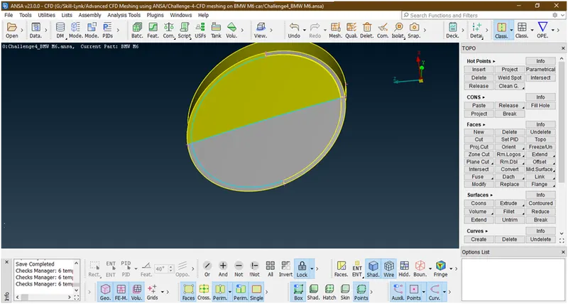
Now these surfaces makes intersection error and we don’t need this so try to delete these.
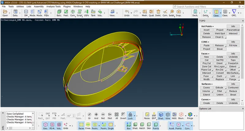
Now we have deleted but there is some thickness showing but we don’t want want this internal thickness inside the logo so we are deleting this.
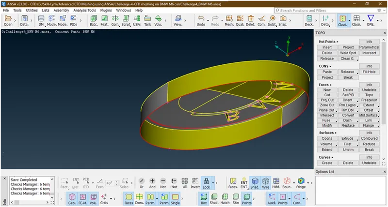
Now we have succesfully deleted but some red cons are form to remove hese red cons just create a surface there
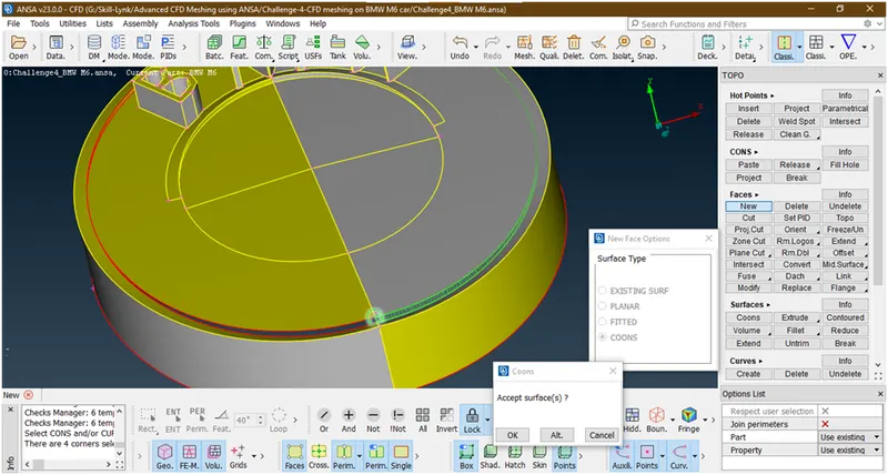
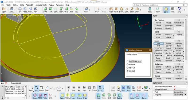
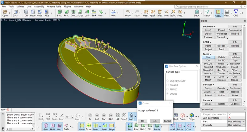
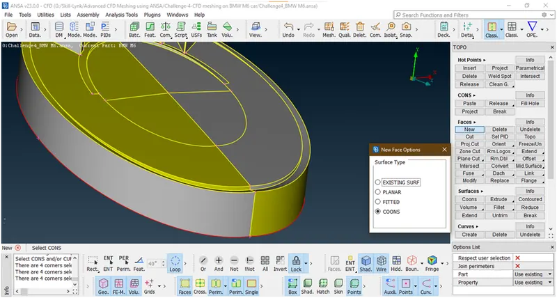
Now it has been created.now click on all
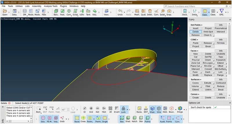
To remove bottom single con just project this con to bottom surface
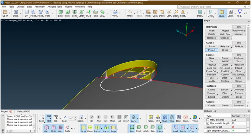
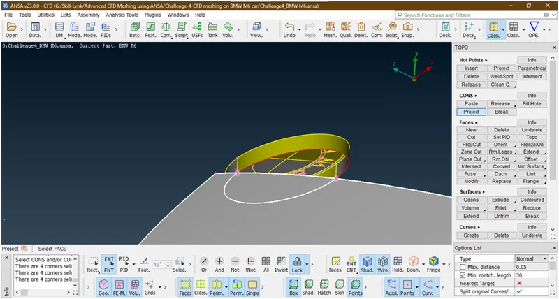
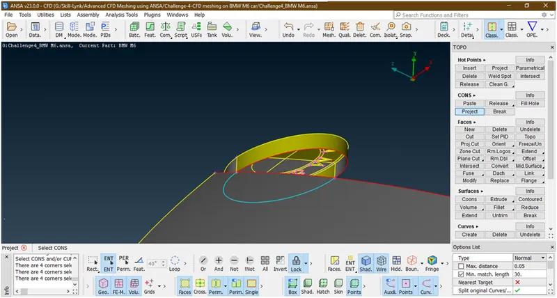
Now triple con has formed .so delete this part of surface.
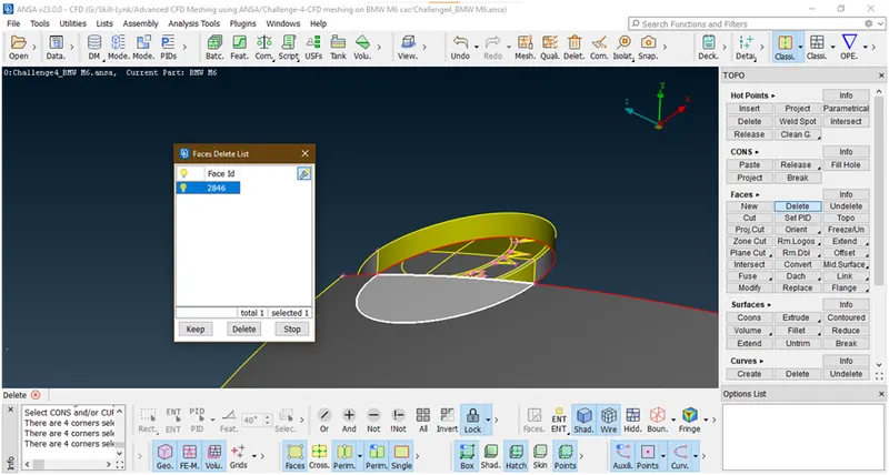
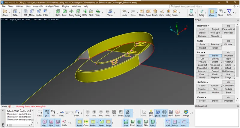
Now we have created geometry there.
- Again lets go for check is intersection is removed or not
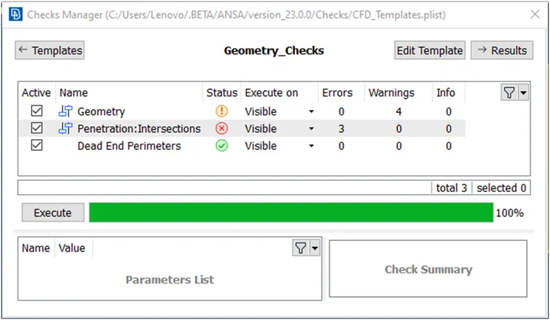
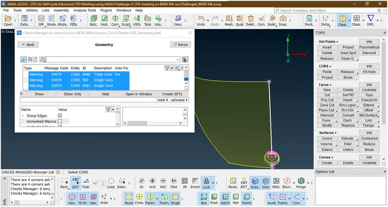
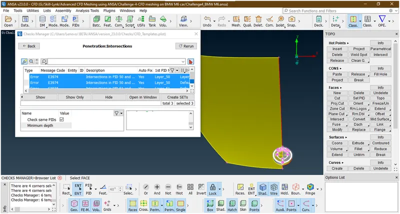
Now we have successfully removed the error between car body and logo.now the errors are only in the logo lets clear these.
- Now hide the bottom surface

The intersection error is occurred due to we have created a small surface lets delete this.
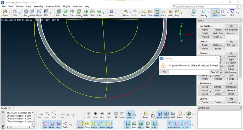
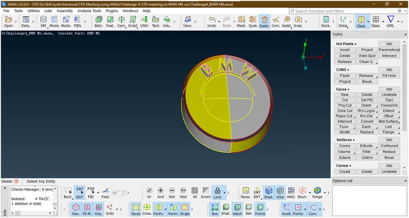
Now again recreate the surface.
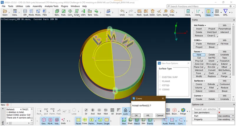
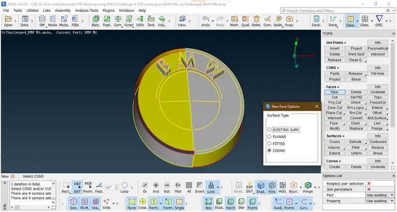
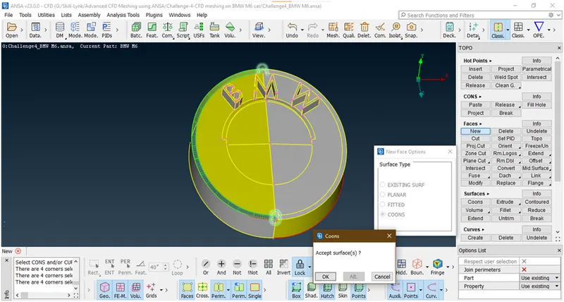
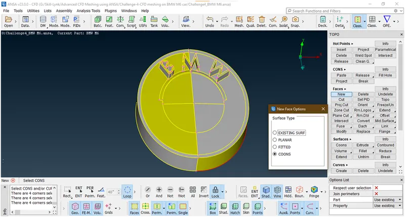
- Now , let check for errors
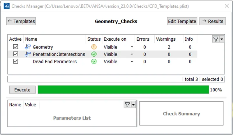
Now we have successfully removed intersection error.
Lets see what are the geometry errors
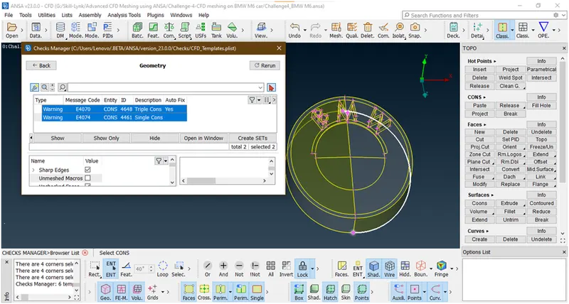
There is some triple con in M so lets clear this.
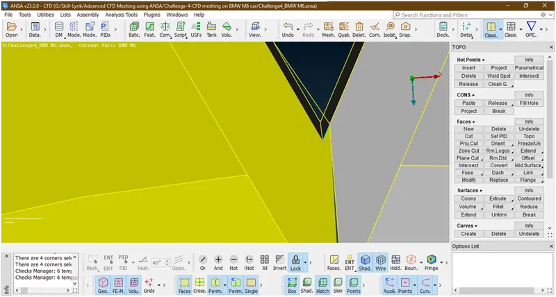
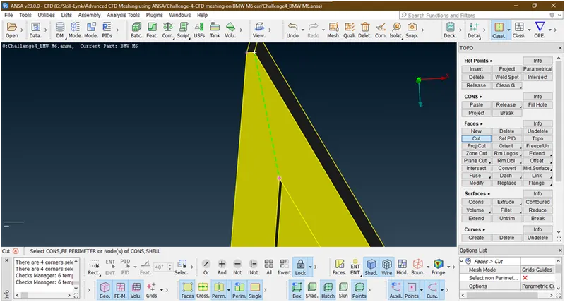
The triple con is here so we are isolating this surface by creating cut there
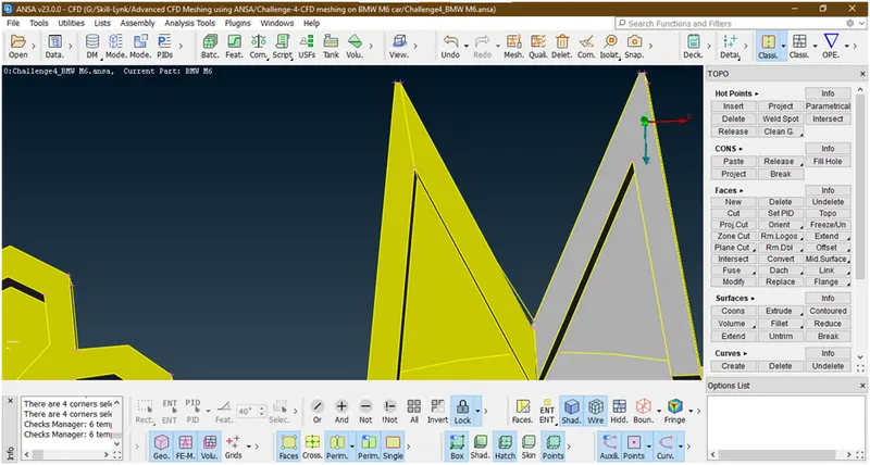
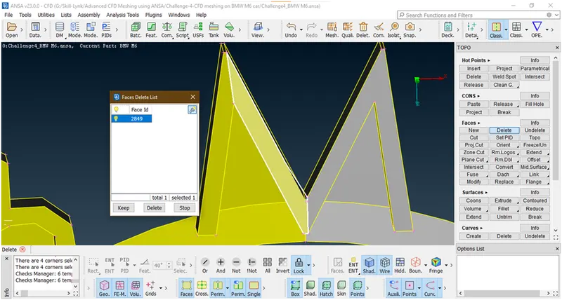
Now try to delete this face
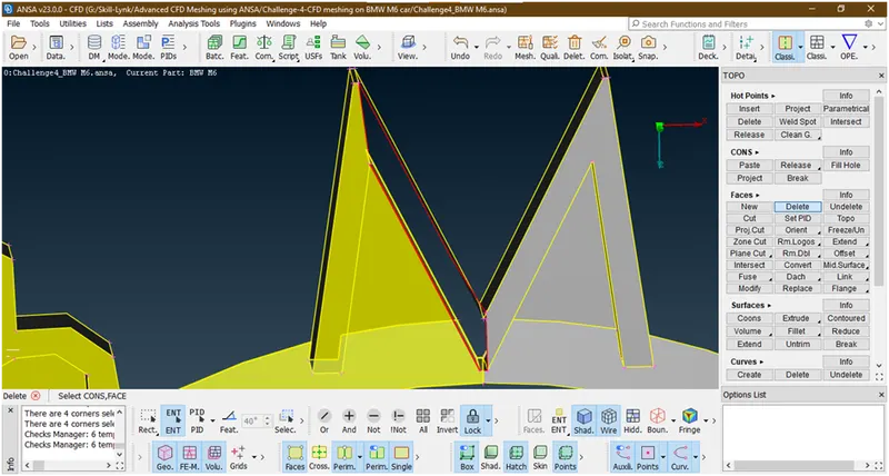
Now try to make a cut here
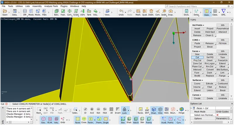
Now we have created and deleted unwanted surface. Similarly we are doing for other side also
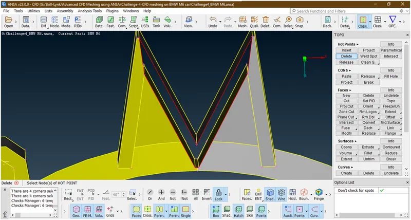
Now create the surface by coons and entity selection mode
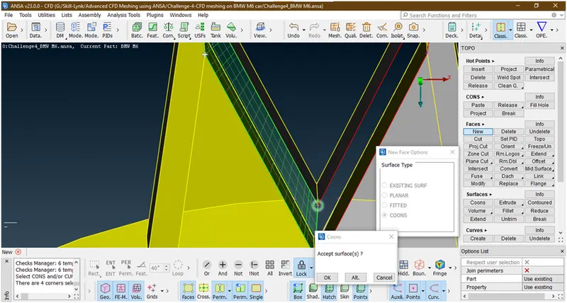
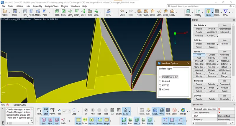
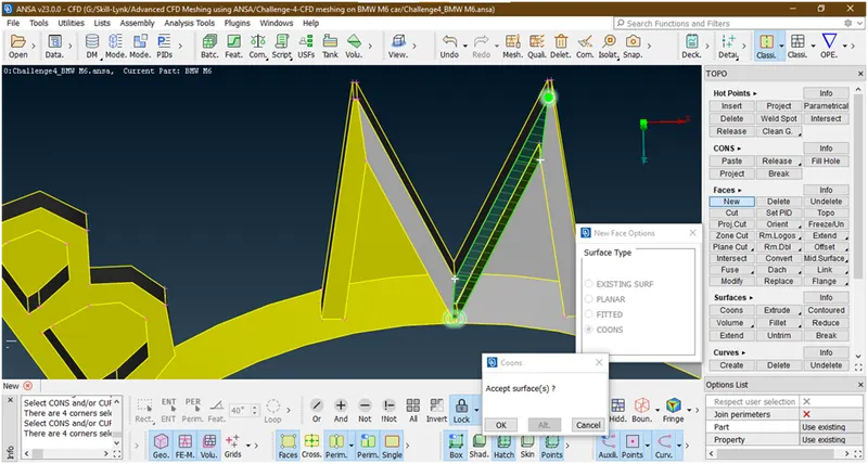
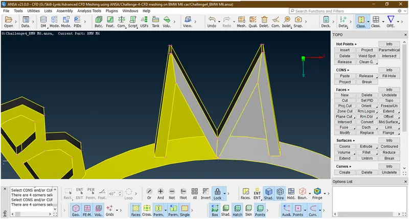
Now lets click on all and check errors
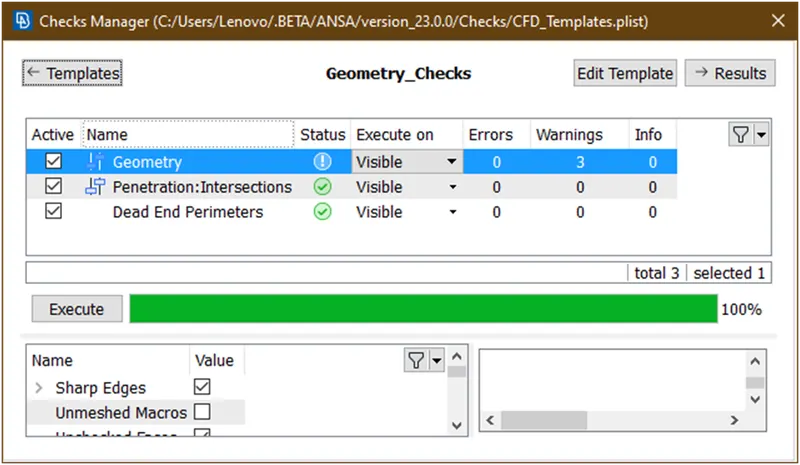
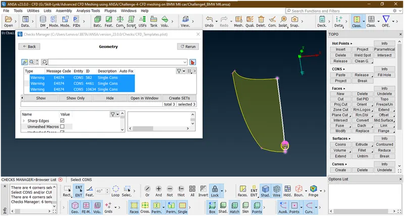
These are the single cons due to we have deleted half part so right now we are ignored.
Now remove lock,click on all and check for errors.
10. Now lets go for windows.
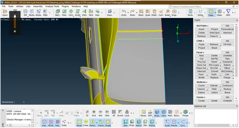
Lets clear this triple con and this is due to overlap surface so we will delete this
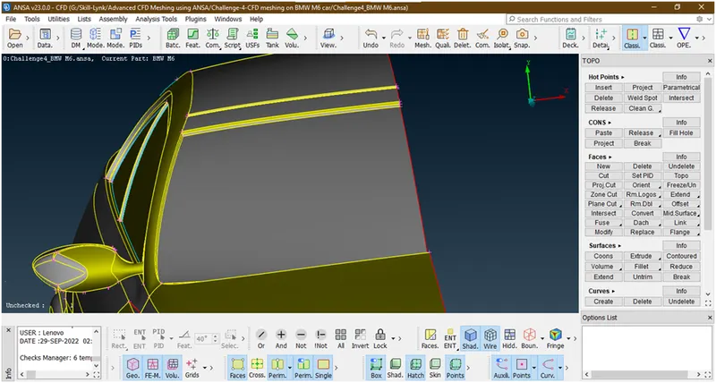
We have deleted this surface similarly we will do for back side window.
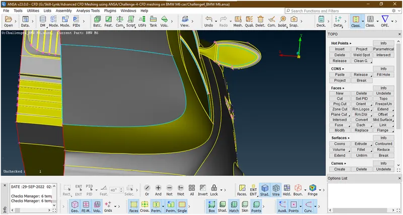
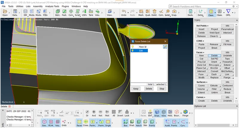
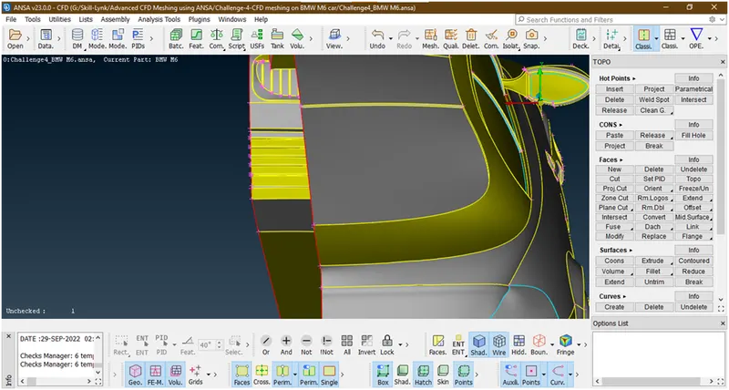
Similaly this overlapping surfaces we are deleting
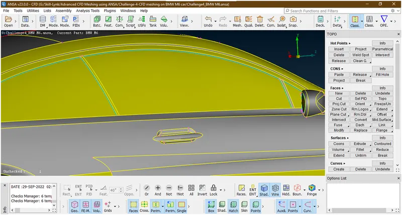
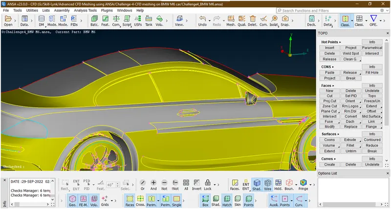
Now we have remove these triple cons from windows.
- Let check for errors
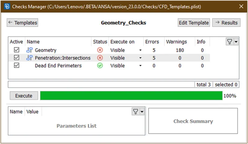
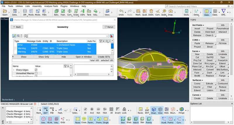
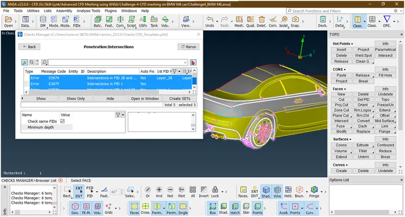
11. Lets clear the errors in the mirror
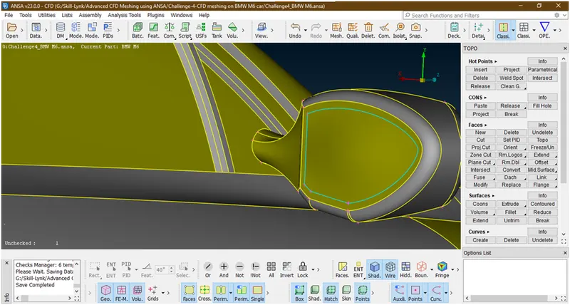
Let hide this and see
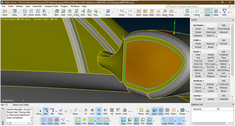
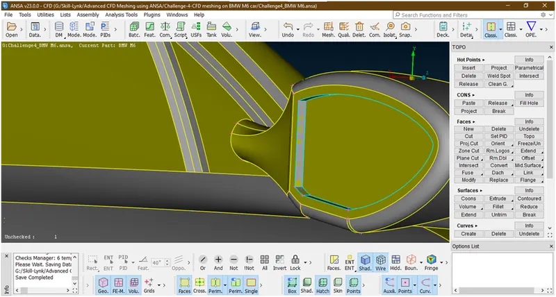
Some overlapping surfaces and internal surfaces are there so let try to delete this.
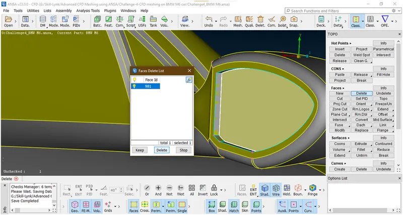
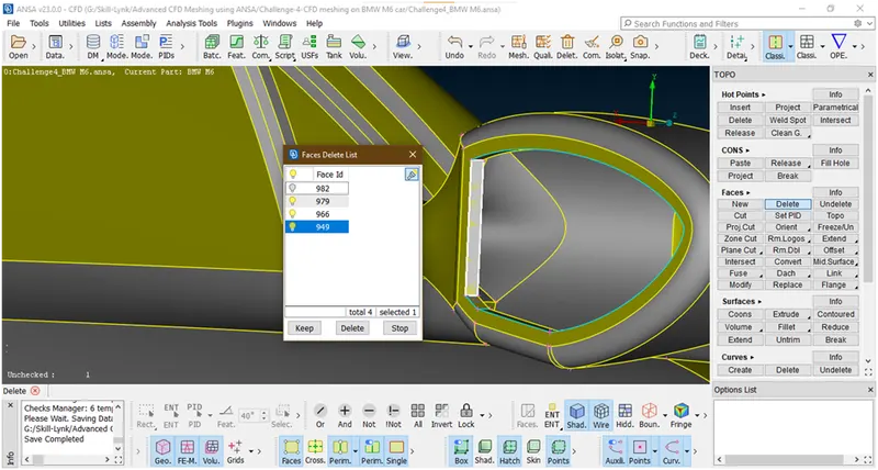
Similarly we are deleting this faces to remove the triple cons.
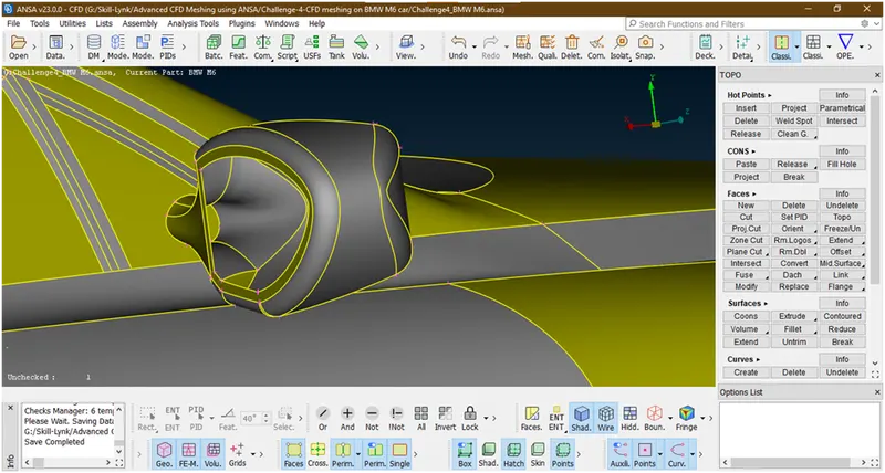
Now we have successfully deleted all surfaces.
There is hollow mirror so it create and another volume we will try to make as a single volume.for that let project this curve and delete this part.
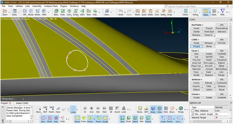
Now select the face
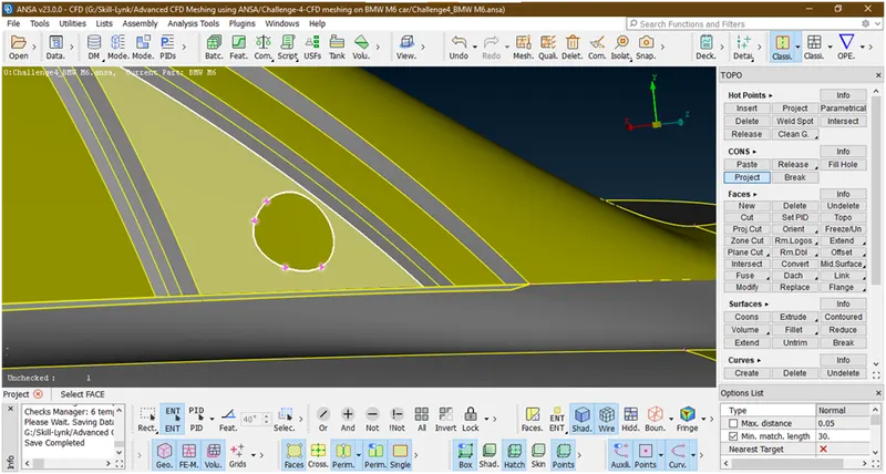
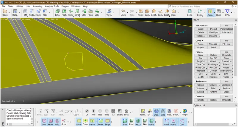
It has been projected but not in good resolution so we will try to change the resolution
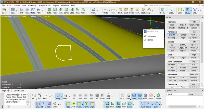
Hit the middle click then a new popup opens
Give length=1,and click on ok
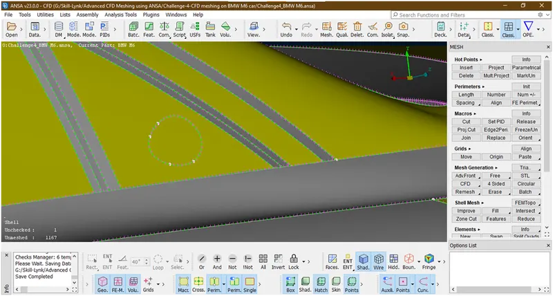
Now it has been in proper shape.now lets goto topo mode and delete this part.
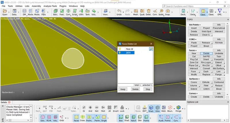
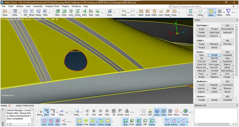
Now click on all
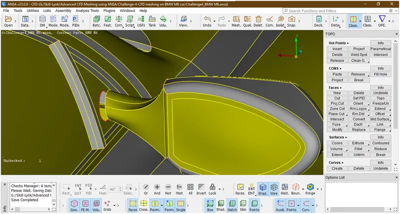
Now delete this face also
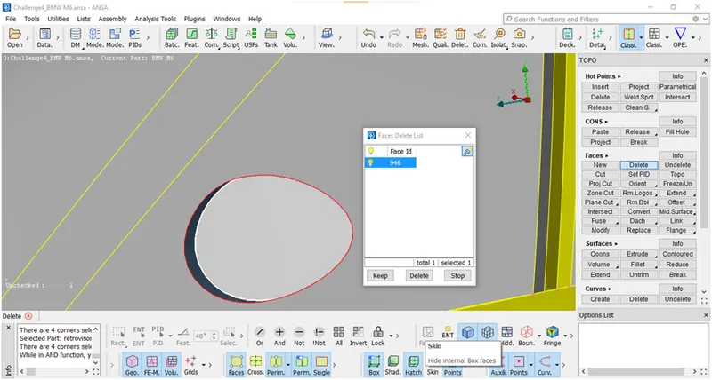
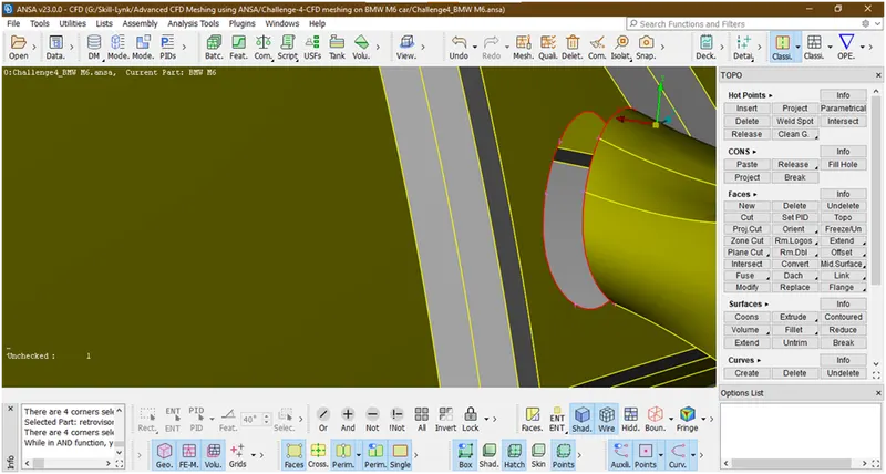
Now there is some little gap so we try to fill by creating surface there
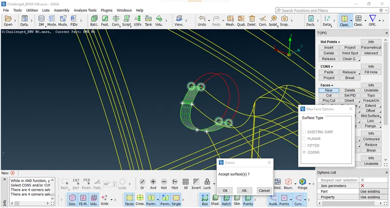
Hit the middle click a popup opens
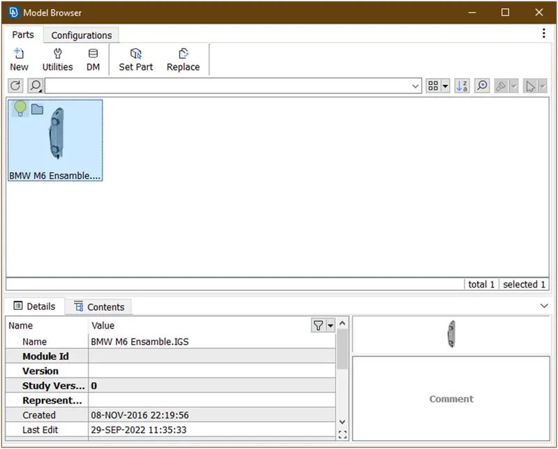
Doble click on highlited,again a 1 more popup opens
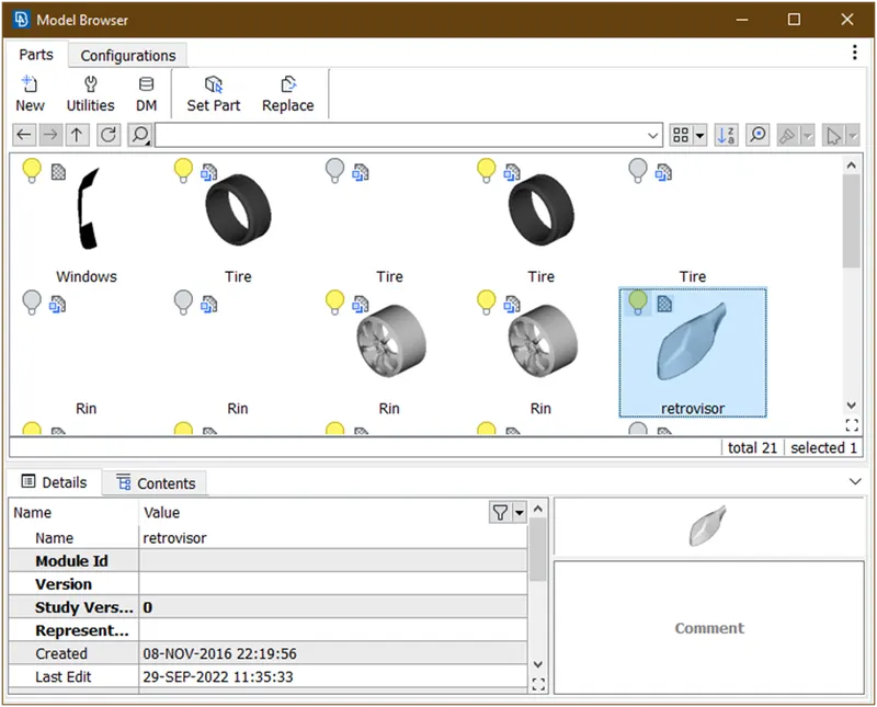
Now find out this and double click on this again one more popup opens
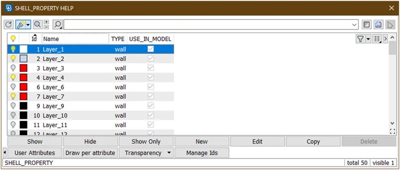
Now double click on this the surface is created.
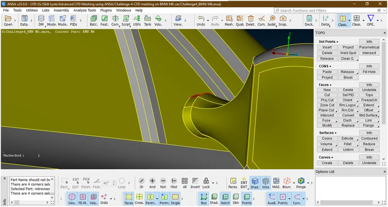
Now do the similar procedure to crate half portion of this surface
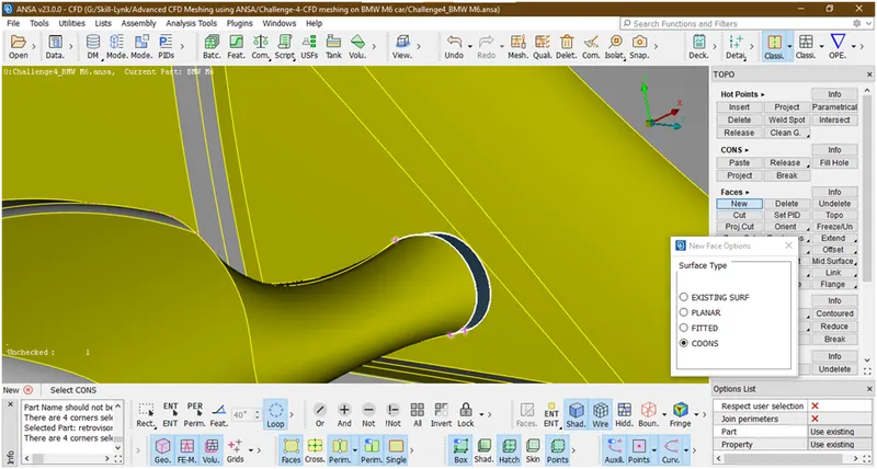
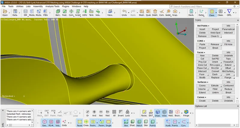
Now we have succefuly created surface there.
- Now lets check for errors
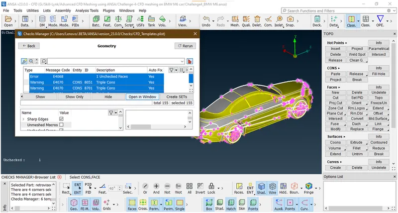
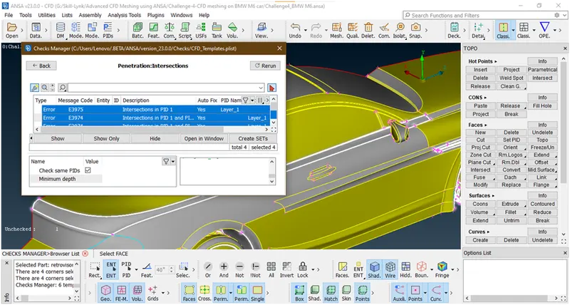
Now we have succefully removed error from mirror.now lets go for next error.
12. There is a single con here so try to remove this
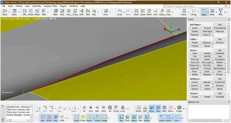
Now recreate the surface there by using fill hole option 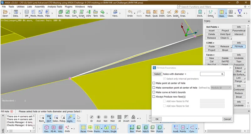
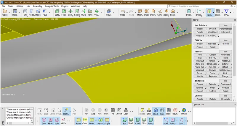 Now will go for next part.
13. Now we are going to clear this section
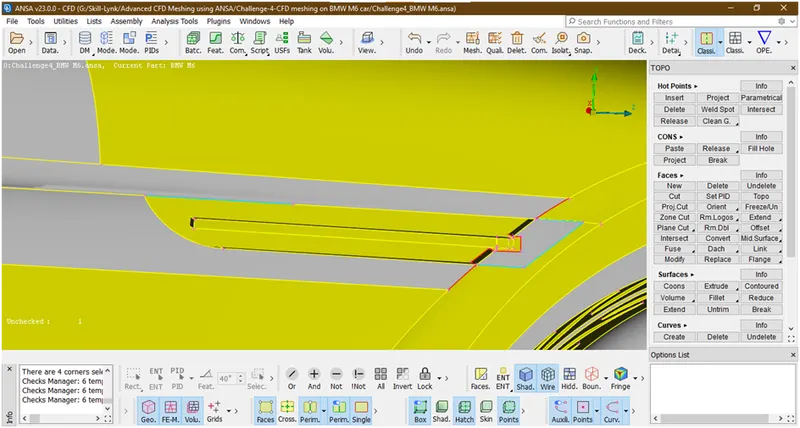
Let hide all other parts and lock it and concentrayr on this surface.
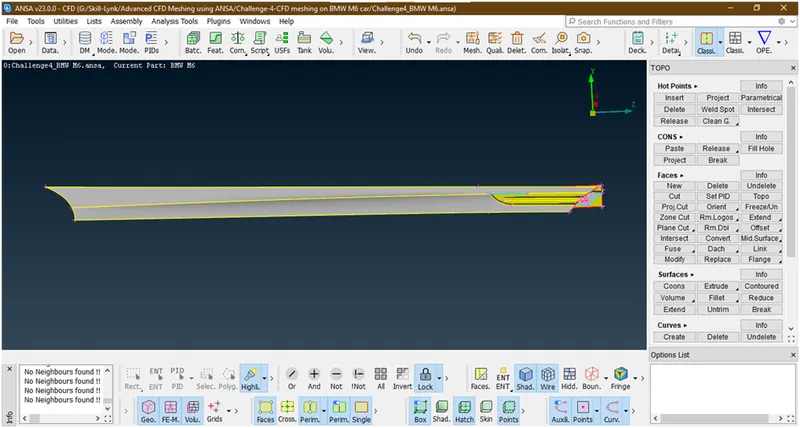
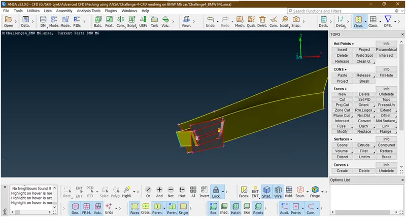
Now this vertical face causes an itersection error so will delete this.
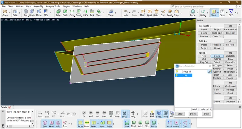
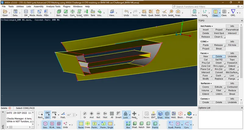
Now let hide the some surfaces.Let try to extend this surface and delete back side portion.
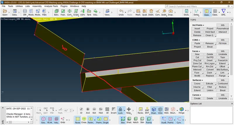
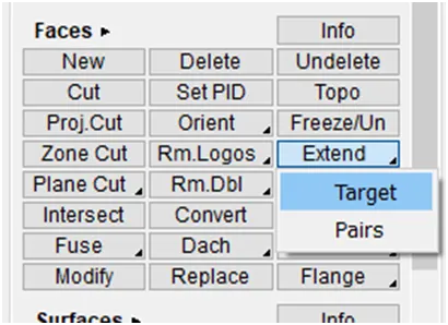
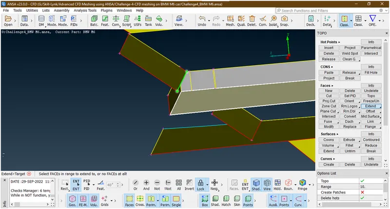
- Goto extend under faces
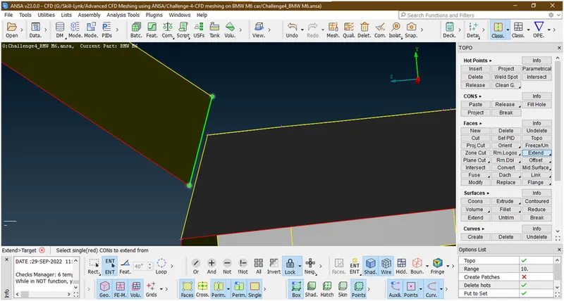
Now select the red con of a surface which we want to extend
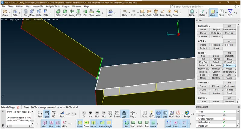
Now hit the middle click and select th face
Now hit the middle click.
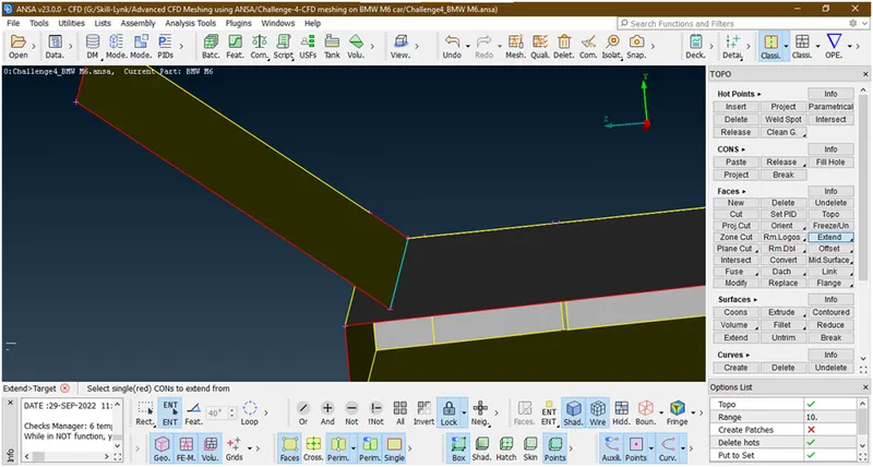
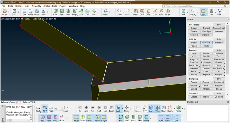
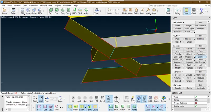
Now it has been extended but we want to wxtend further for that release this triple con by using release tool under cons
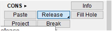
Now select the con
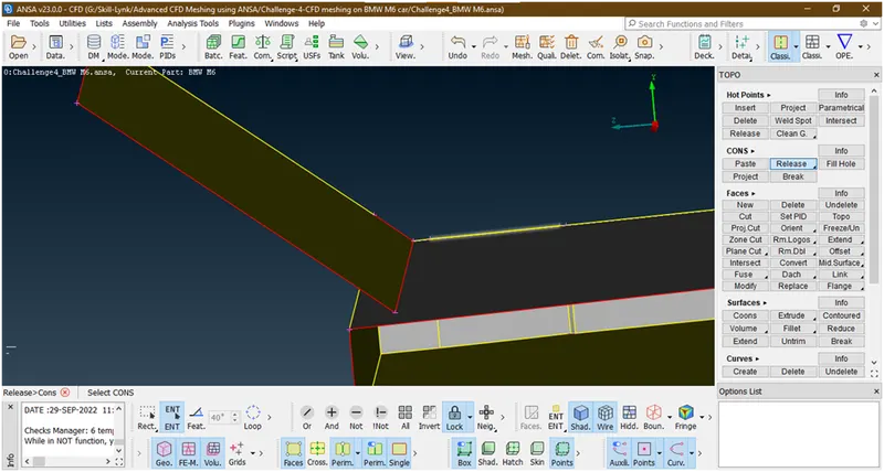
Now hit the middle click
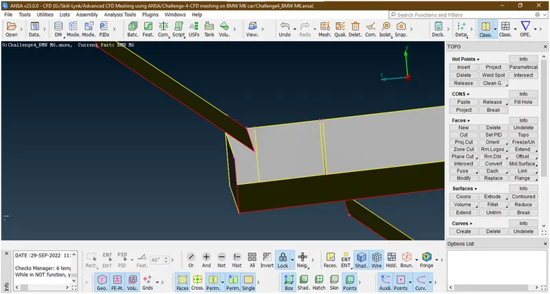
First of all hide this surface

Now again select extend-> select this con-> and select faces
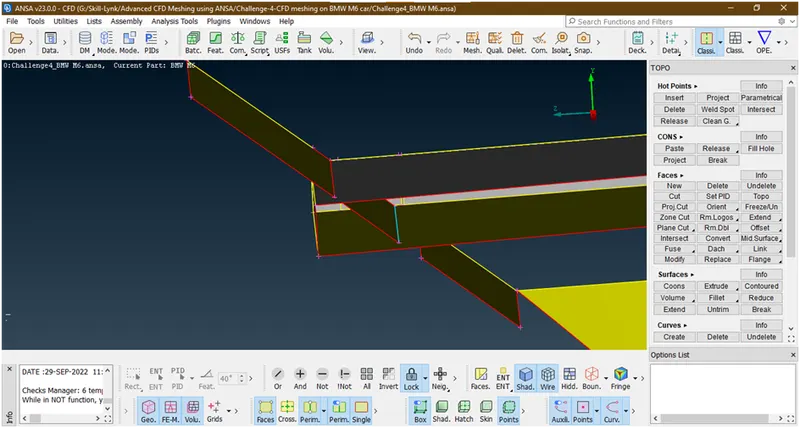
Now click on all
Now project this con on this surface
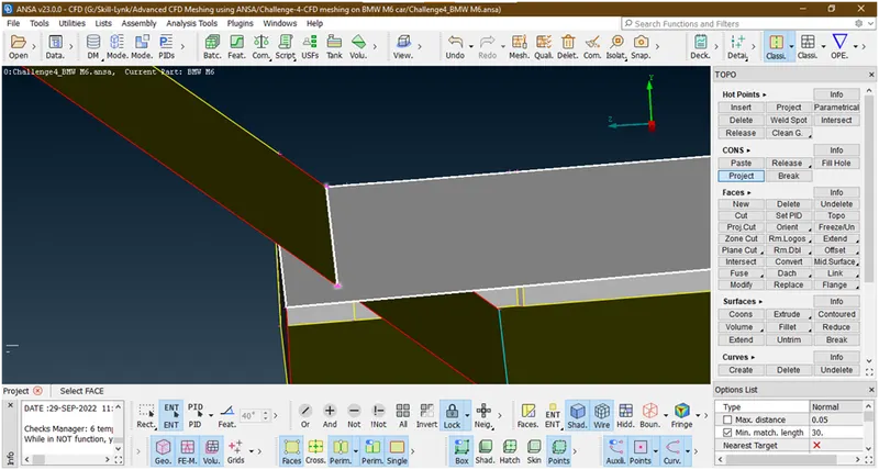
Now it has been projected
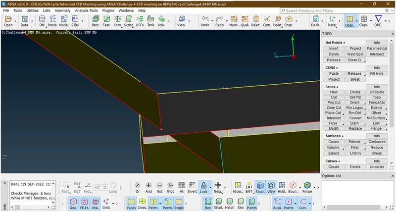
But we are unable to see so lets apply topo here
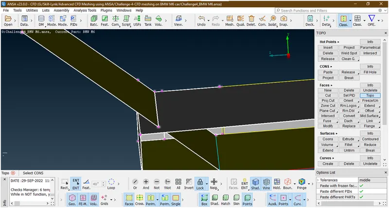
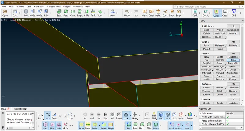
Now mak a cut here bacause of not join proper
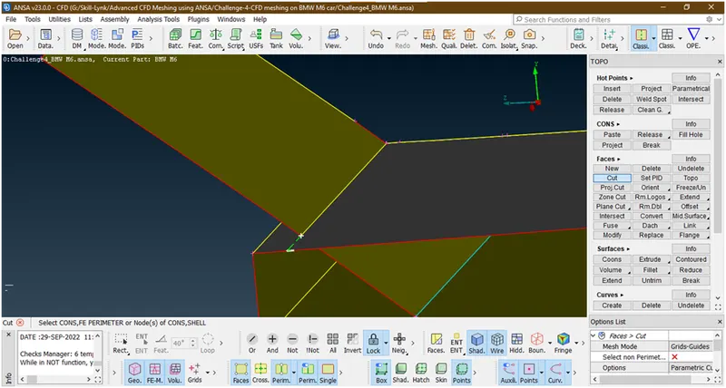
Now we will delete this faces
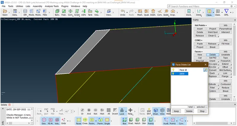
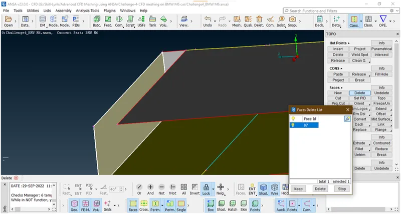
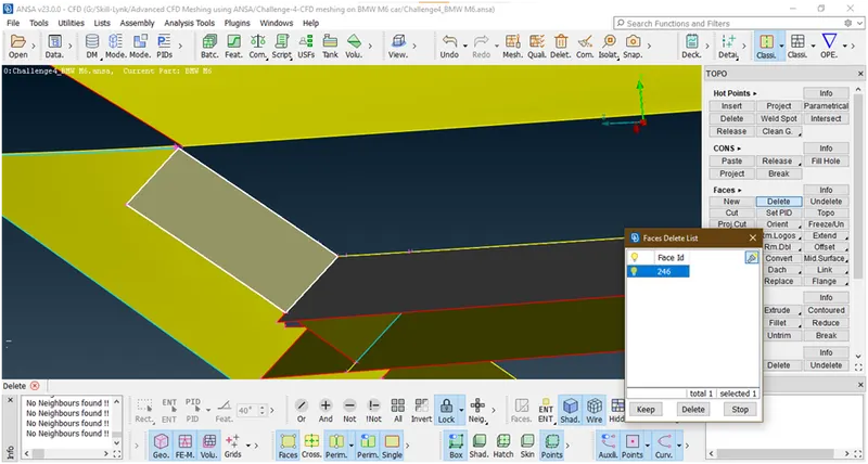
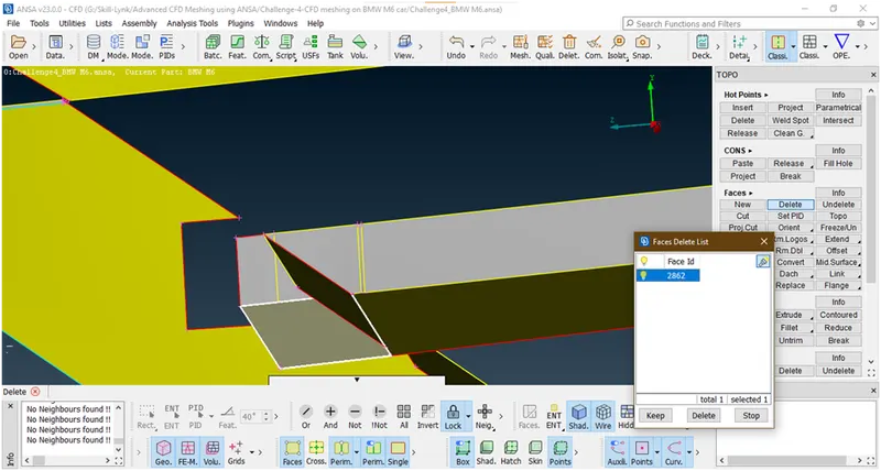
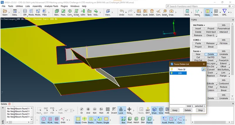
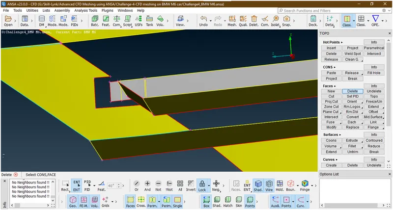
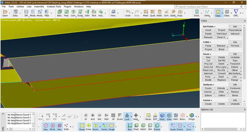
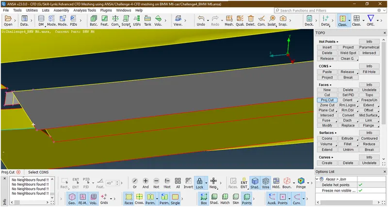
Now we are deleting this extra part by creating a cut by using project cut tool.
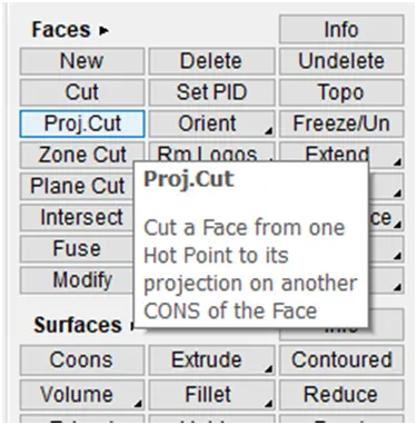
Now select hotpoint
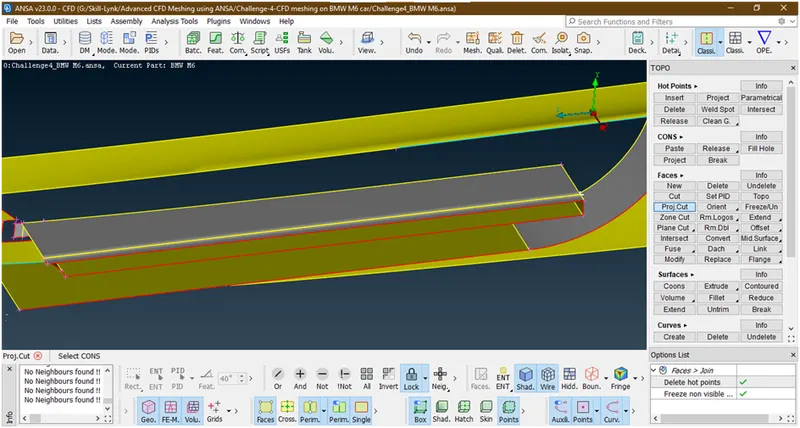
Now select the con
Similarly we are creating this
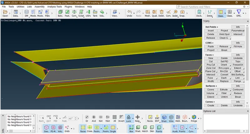
Now deleting these faces
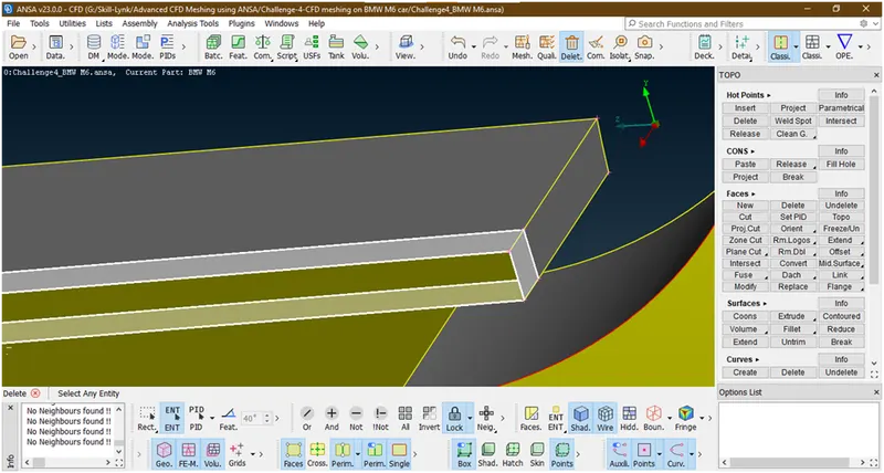
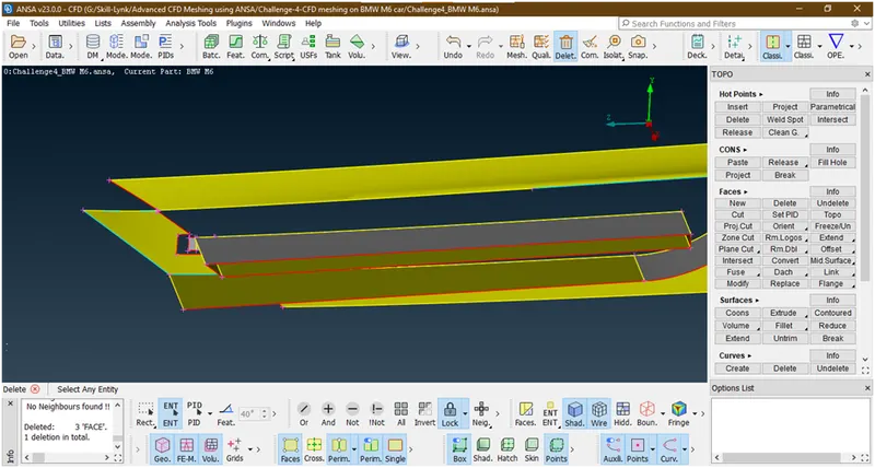
Now click on all
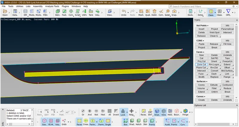
Now we are deleting this faces
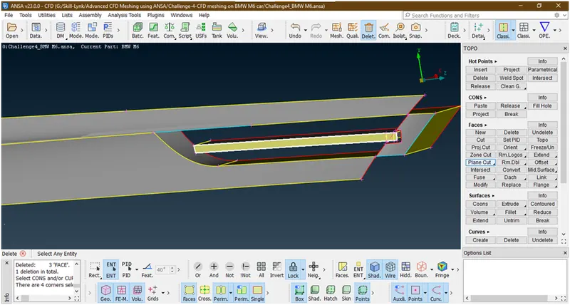
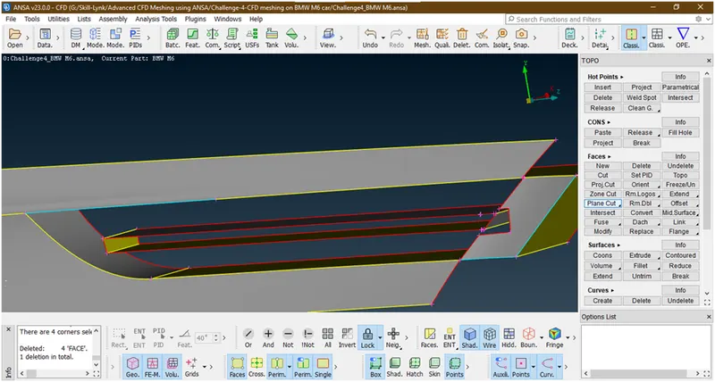
Now delete the extra hotpoints and create a surface there
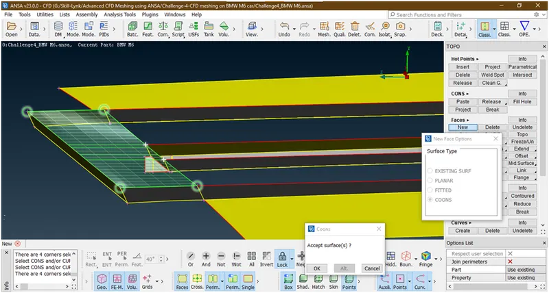
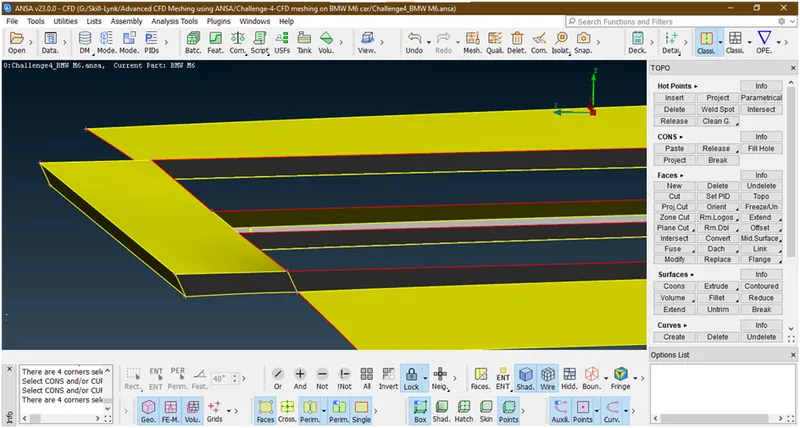
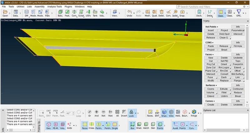
Now simillarly we are creating on font side
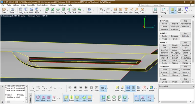
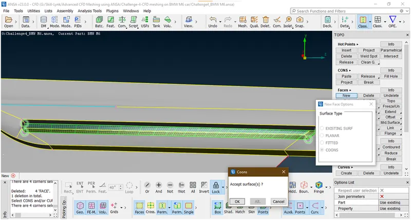
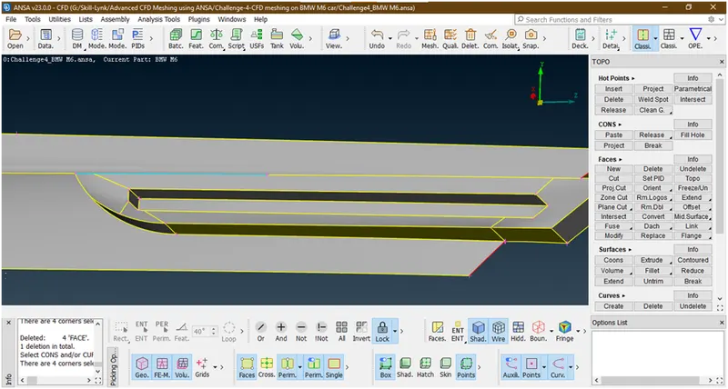
Now there is a triple con see this is a small surface to delete this
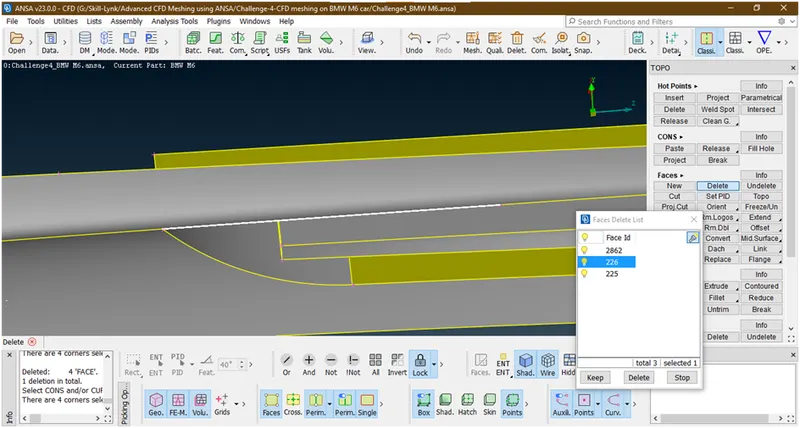
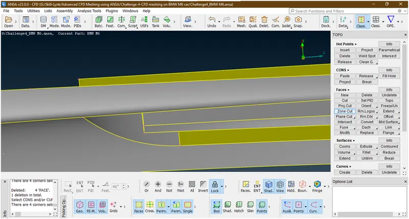
Now we have deleted
Now remove the lock and click on all
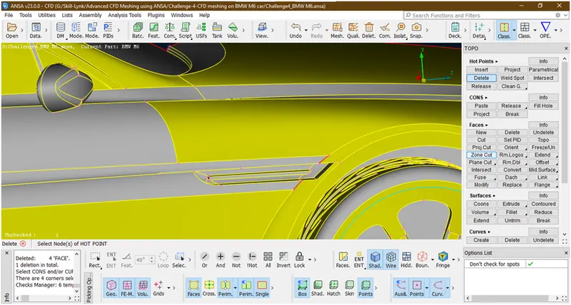
Now these are red cons are nothing but crack so just create a surface there by fill hole tool.
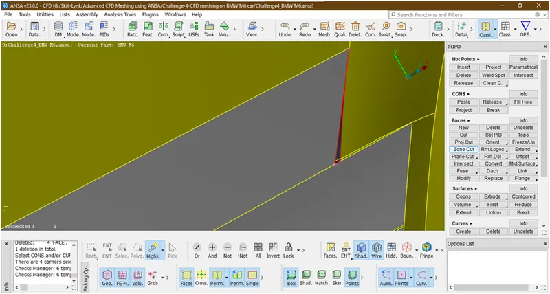
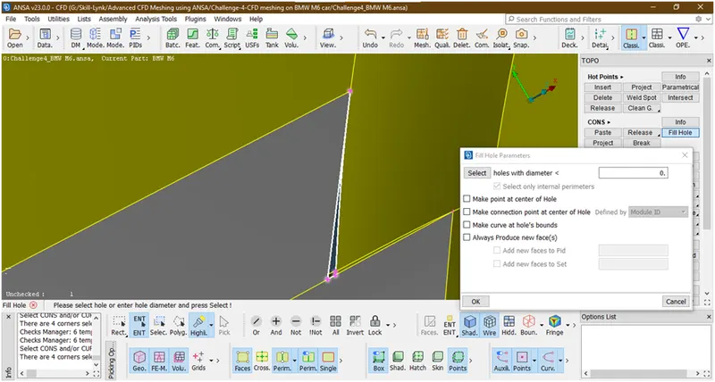
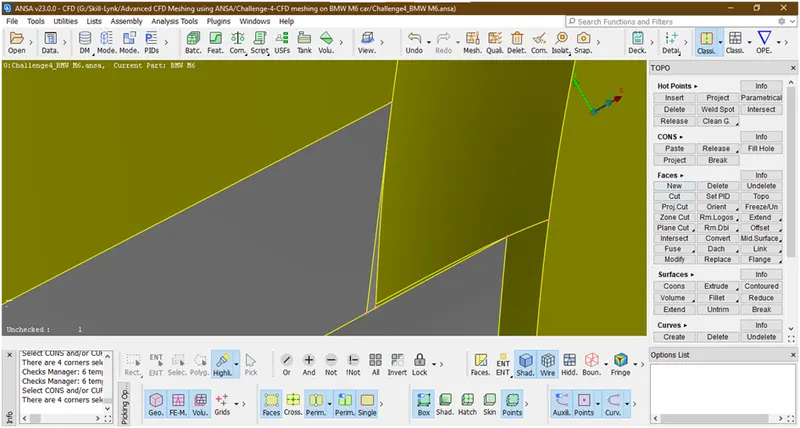
Create a cut there and delete this surface and recreate the surface
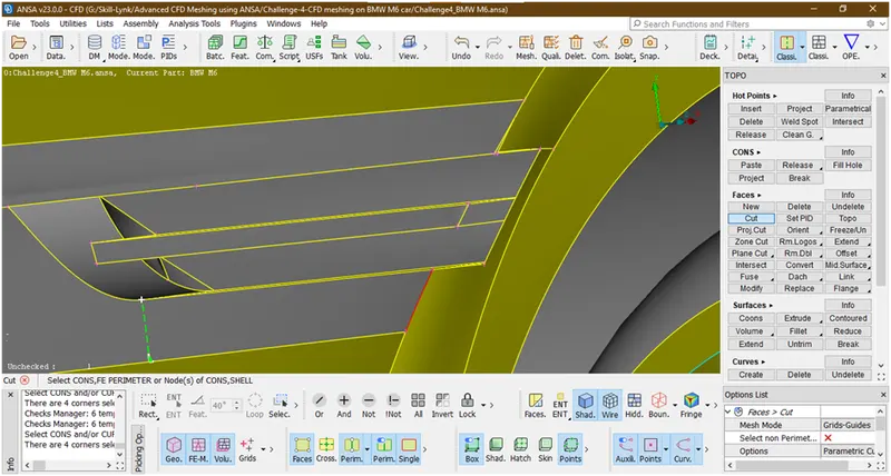
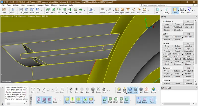
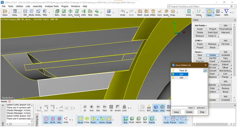
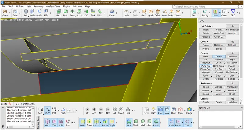
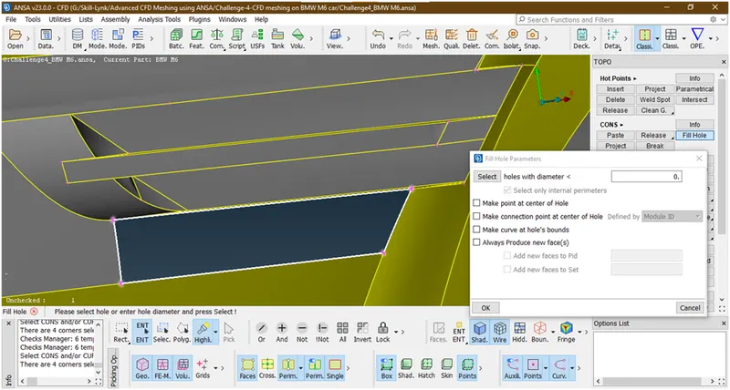
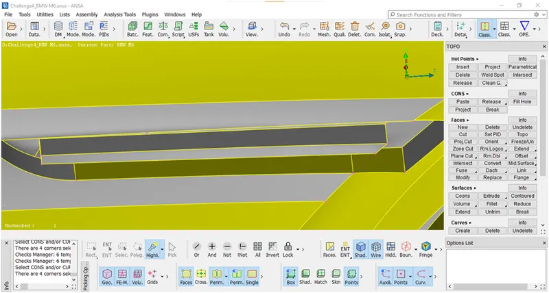
Now we have succesfully clear the errors here.
- Let check for errors
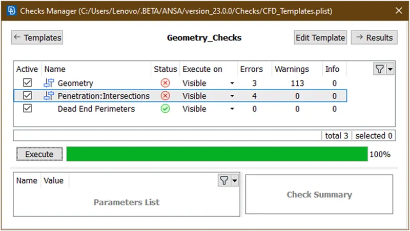
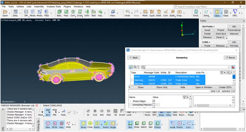
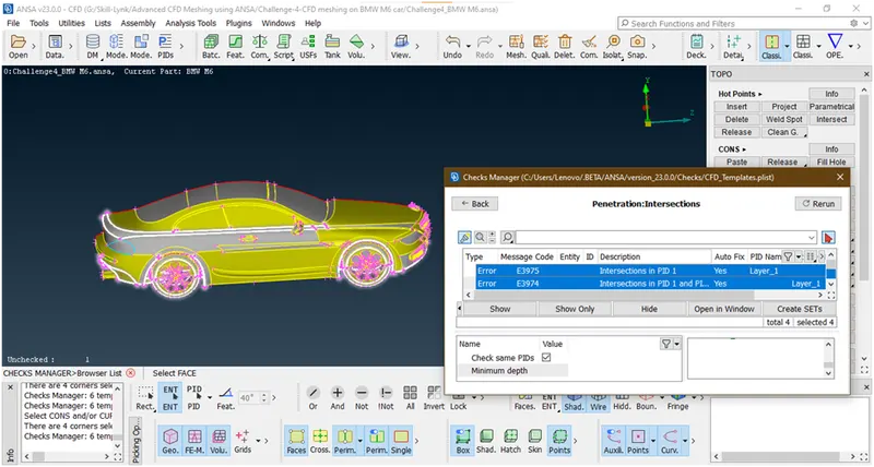
Lets go for next part.
14. Let delete these extra surfaces
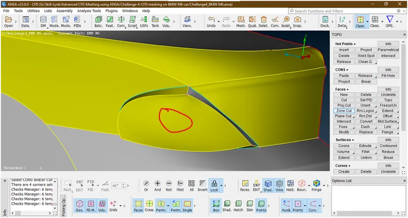
Now this is an extra surfaces so delete it
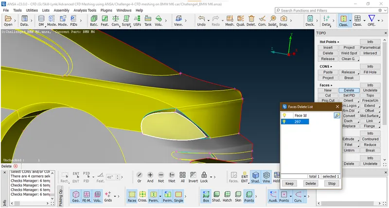
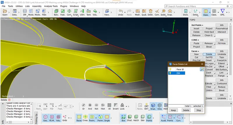
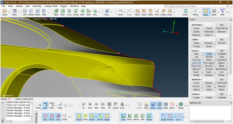
15. Lets clear an intersection error here
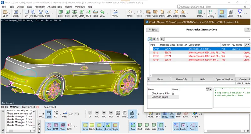
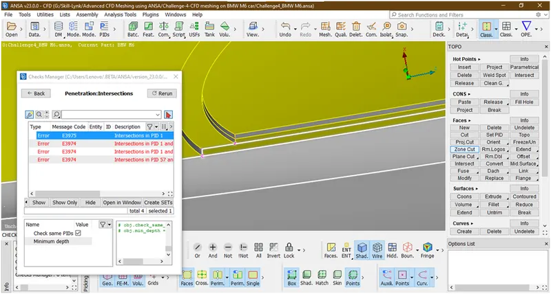
This occurred only in window lets try to resolve
Simply delete this face and recreate the surface
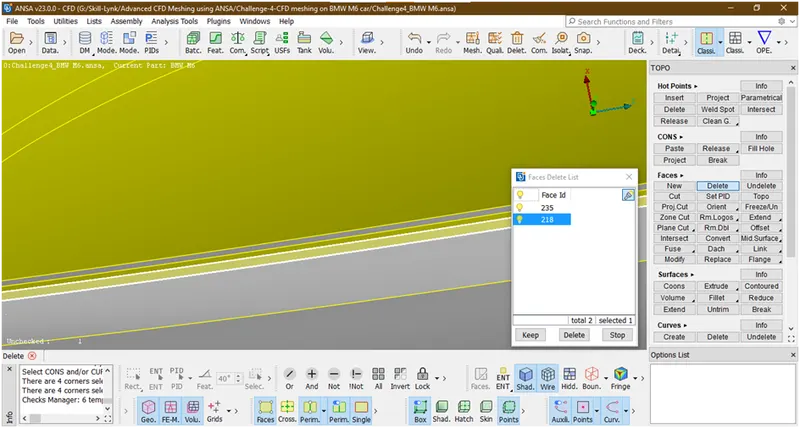
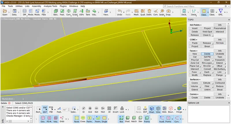
Now create the surface there
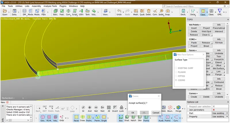
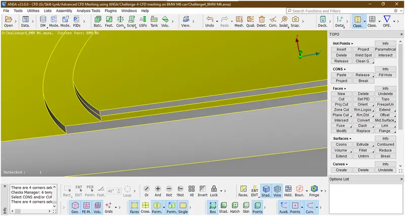
Now it has been created.
- Lets check for intersection error is gone or not
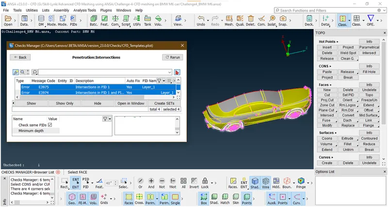
Now it has been removed.
Now lets removed the error in next part
16. Lets see here
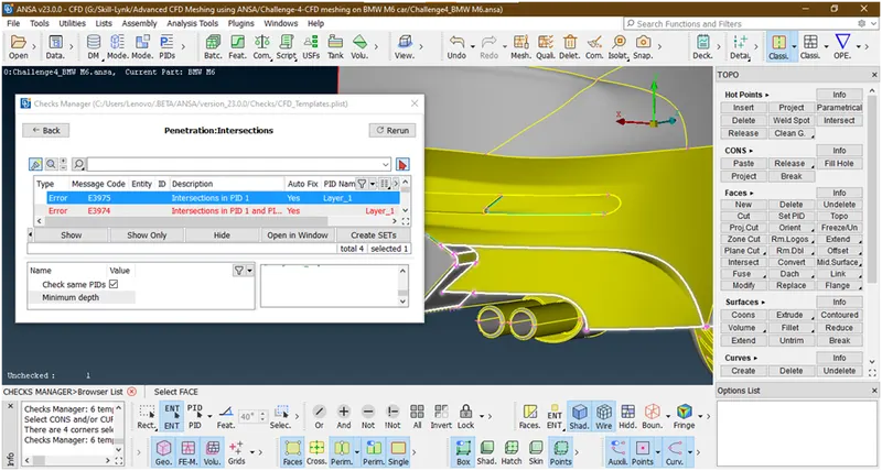
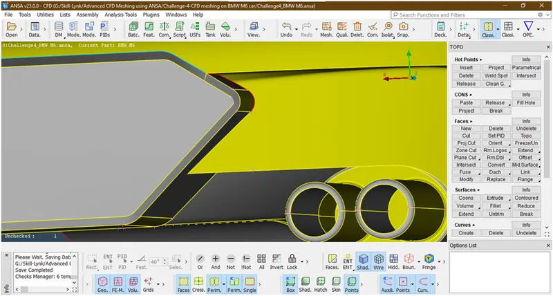
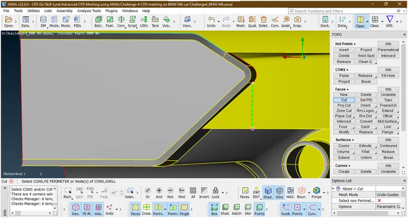
Lets make a cut there
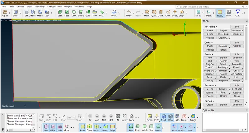
Now delete this surfaces
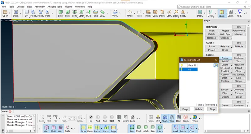
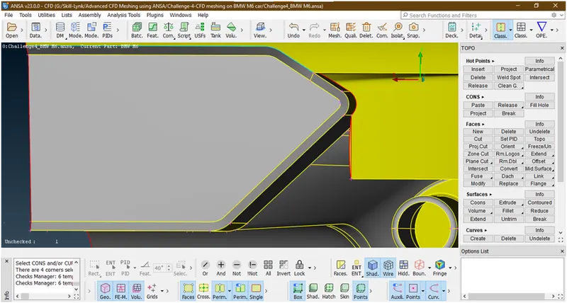
create a new surface there
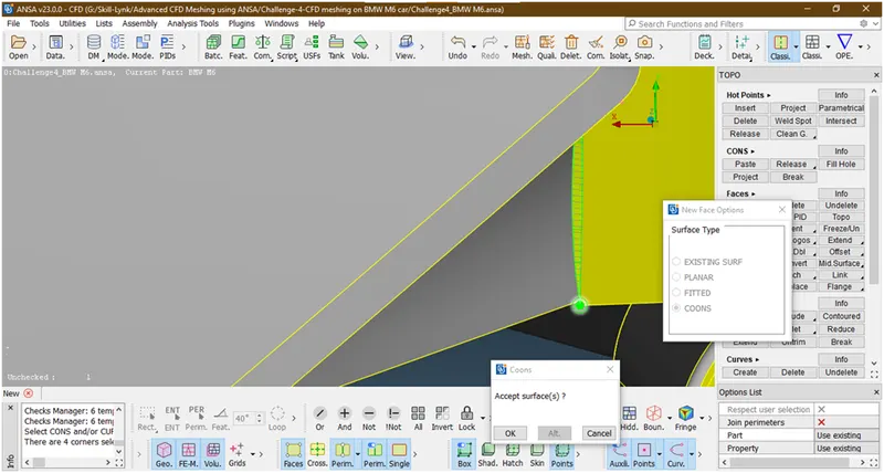
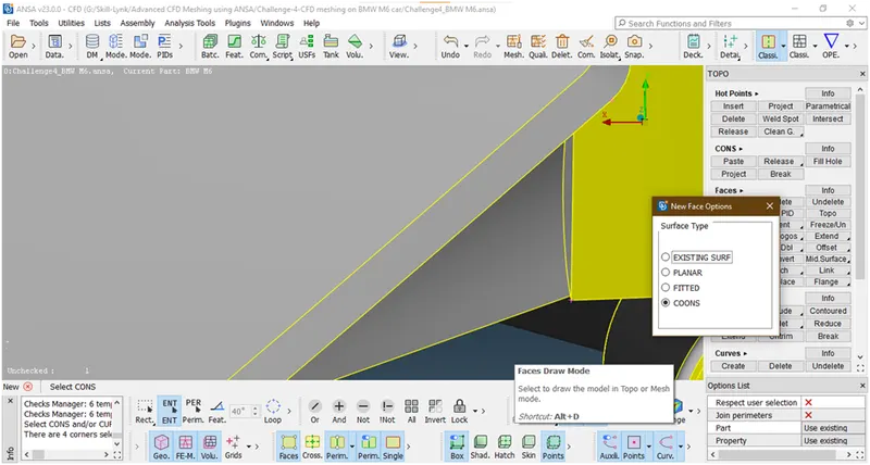
- Now let check for errors
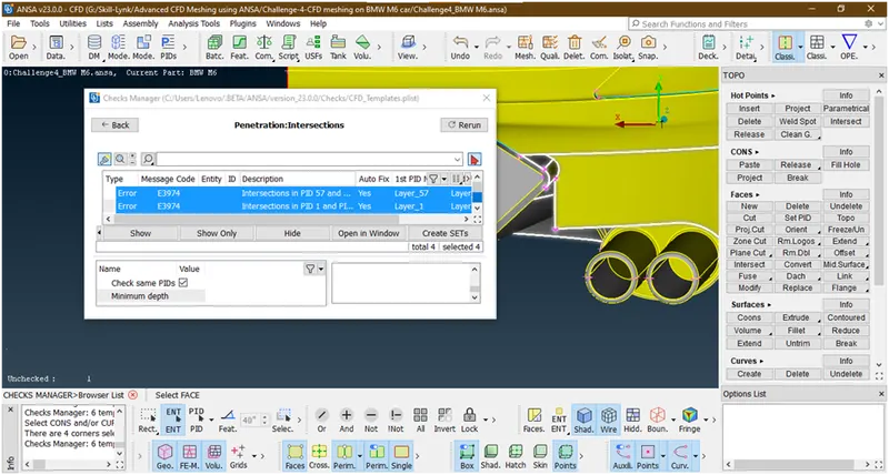
Now this is removed.
17. Lets go for next part
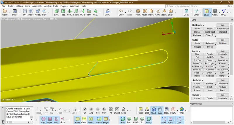
Lets cler this triple con
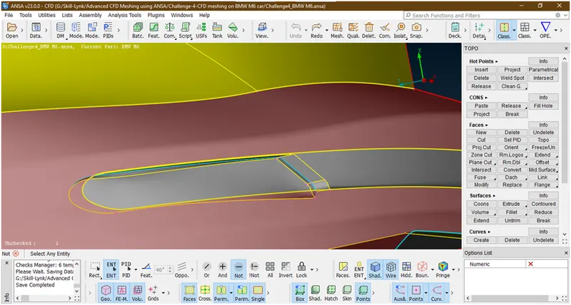
Now this is due to overlaping surface lets delete this.
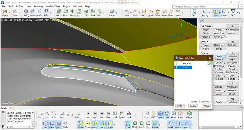
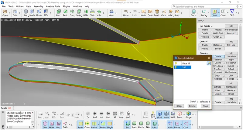
Simillarly we are deleting all unnecessary surafces.
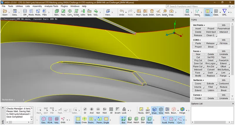
Now we have removed all triple cons from here.
18. Lets go for next part.
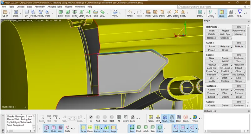
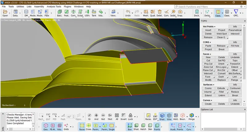
These are unnecessary surface inside the car bacause we are going for external flow analysis so delete these faces.
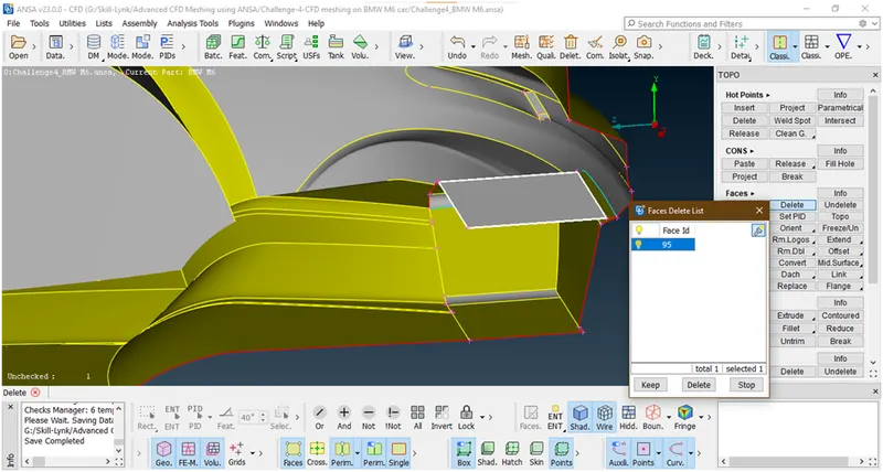
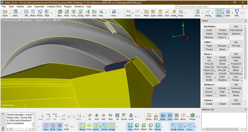
Now we have deleted.
Lets create the surface where single con shows.
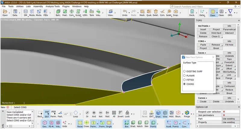
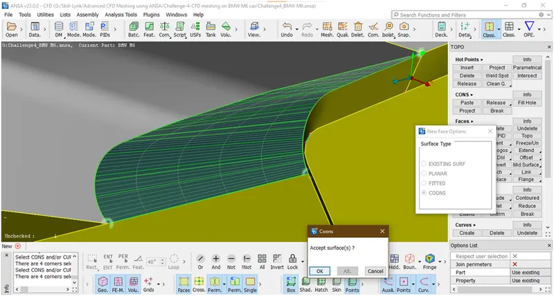
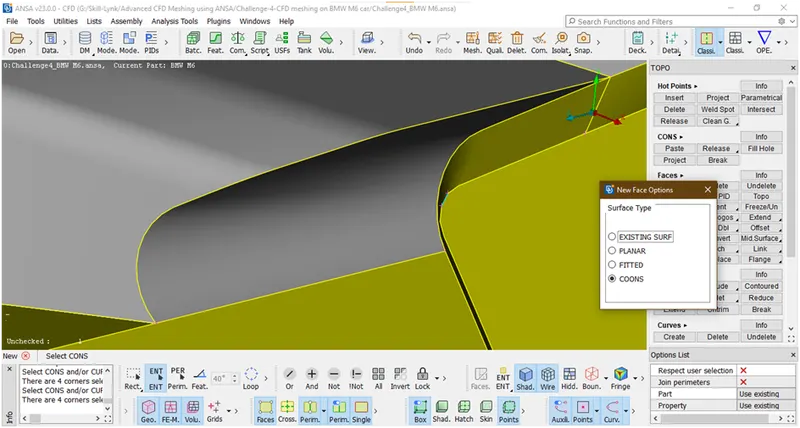
Now its done.
- Now lets check for errors.
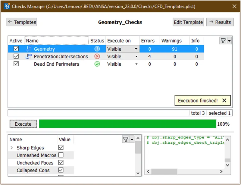
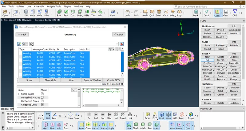
These are single cons which are due to we have deleted half portion and some triple cons shows which are in tyres.
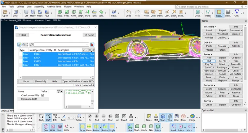
These are the intersection errors are due to floor only and some surfaces are gone into tyres.
19. Lets clear the floor
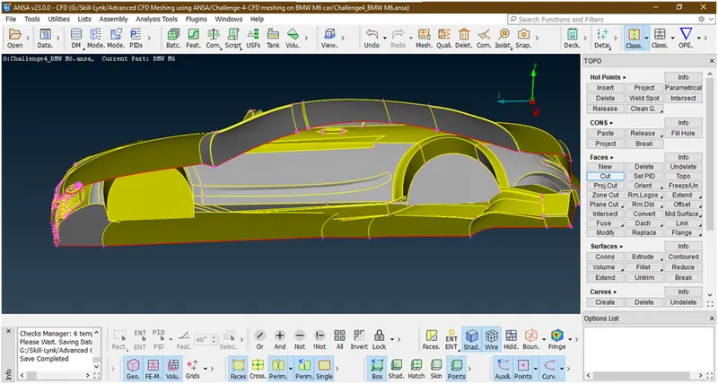
Lets hide all other parts by using not tool
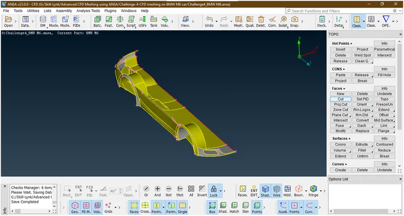
Now we have hide all other parts lets lock it. Lets delete the floor surfaces.
- Before deleting we need a guiding line to make a new surface with same distance. So we are creating curves at single con with the help of cons2curv tool and taking reference as red cons.
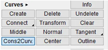
- Goto cons2curv under curves
Now select the cons
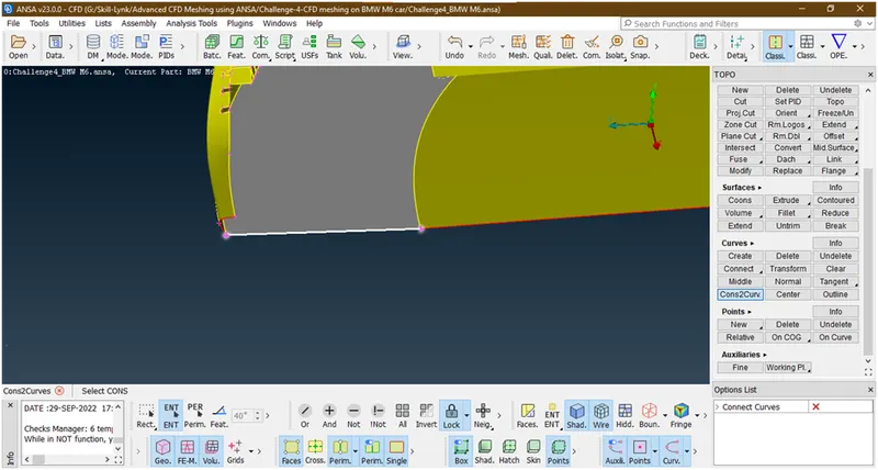
Hit the middle click
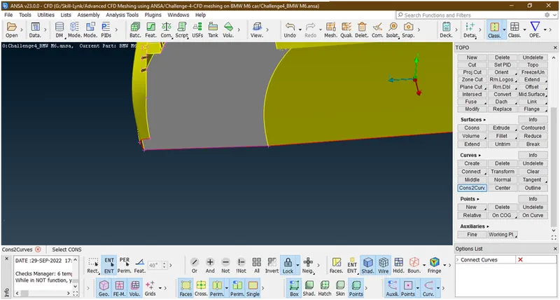
Similarly we can do for other cons
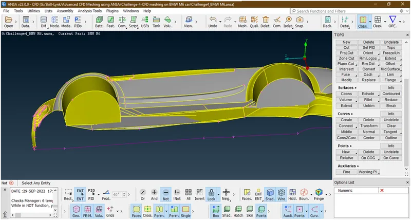
We have created the curves
- now click on all. Let see in the first rim that by deleting the surface cause any intersection error while creating new surface
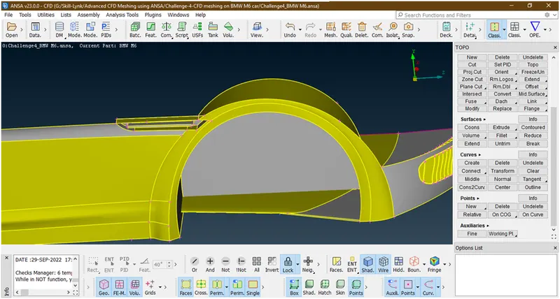
Now these are not creating any problem so we are deleting these faces.
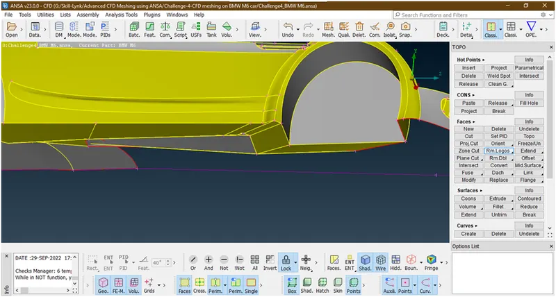
Now we have deleted these faces.
- Lets go for next rim and check
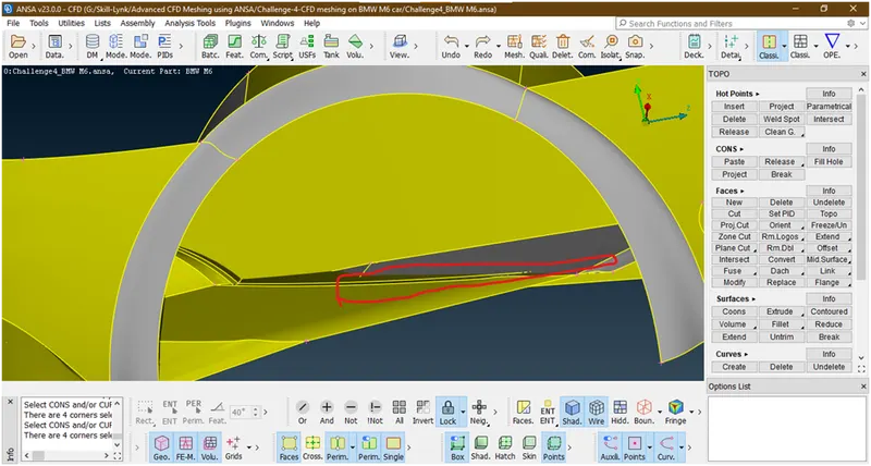
Now these surfaces which are maeked are not create an intersection error so we will go for delete these faces.
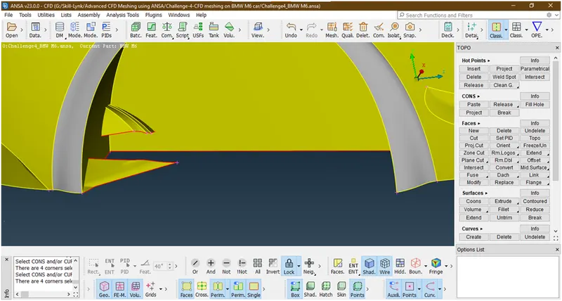
Now we have deleted the syrfaces which creates an error as shown above and below figure.
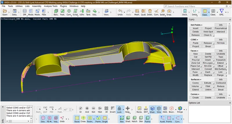
- Now in rim some faces are which we cant delete totally.
Lets apply intersect tool and delete the portion of thes faces which are gone into the rim.for that goto intersect under faces
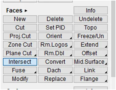
Now it asked for select 1st face so select
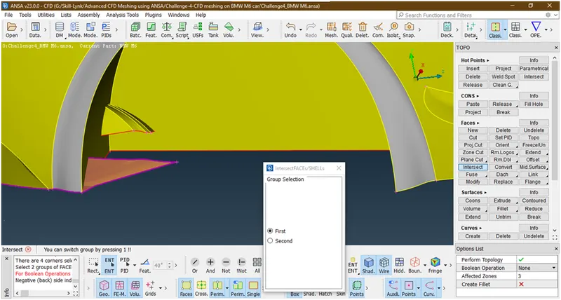
Hit the middle butten and select 2nd face
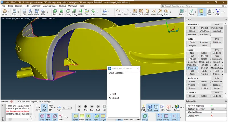
Now hit the middle click then it asked for which faces want to delete so delete unwanted part
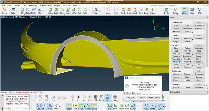
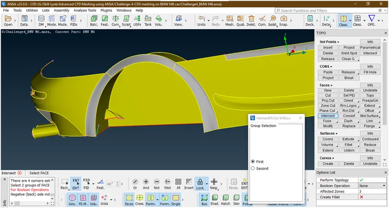
Now do the same procedure for other surfaces also
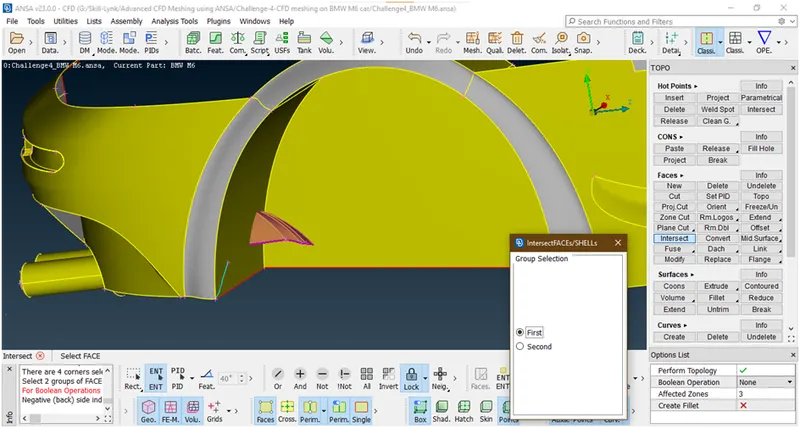
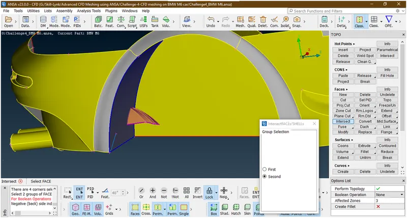
Now delete these faces
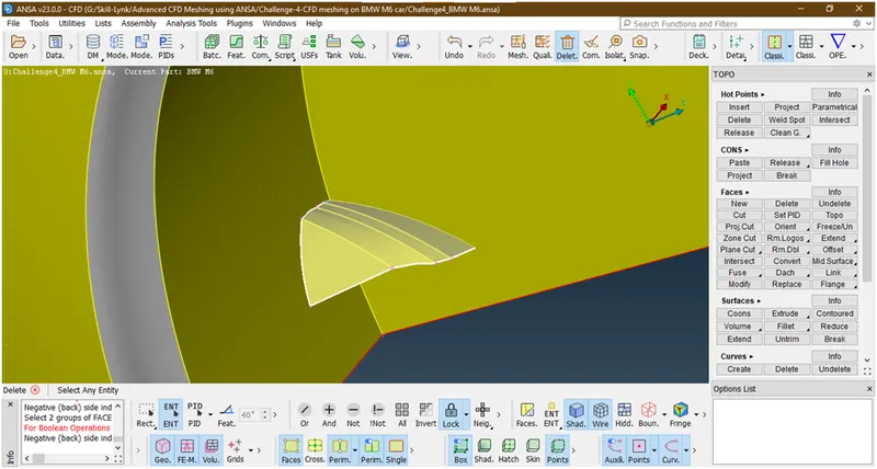
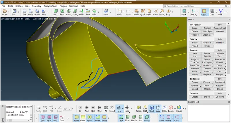
Now we have deleted. There is some triple cons shown to make cut there and delete marked portion because this will create an some intersection error.
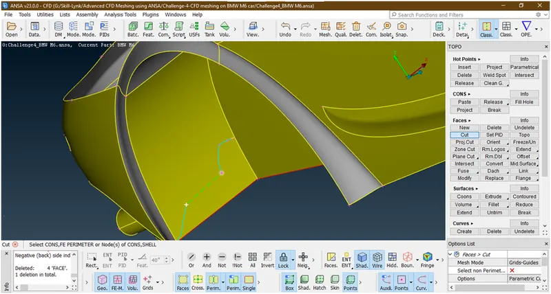
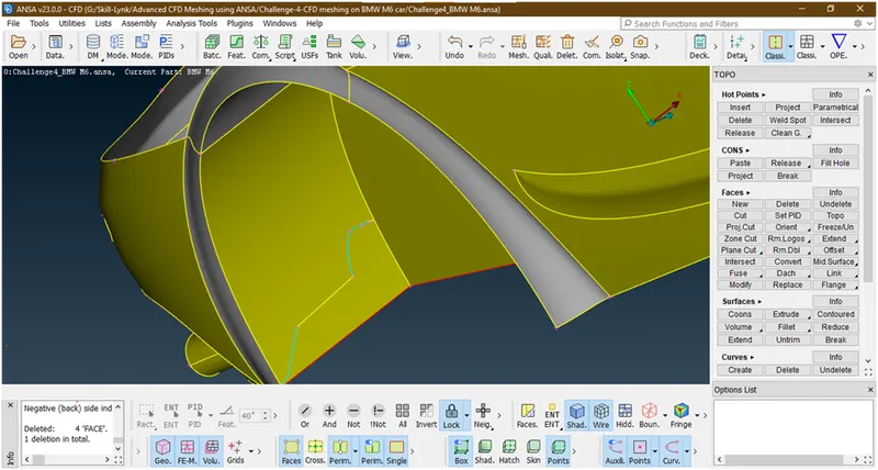
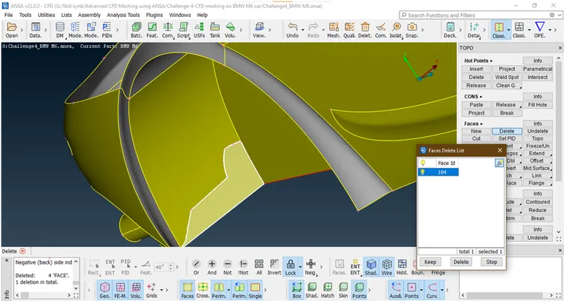
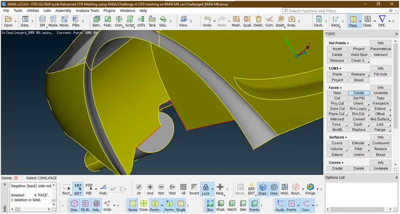
Now we have deletd.
- Lets crate a floor surfaces.
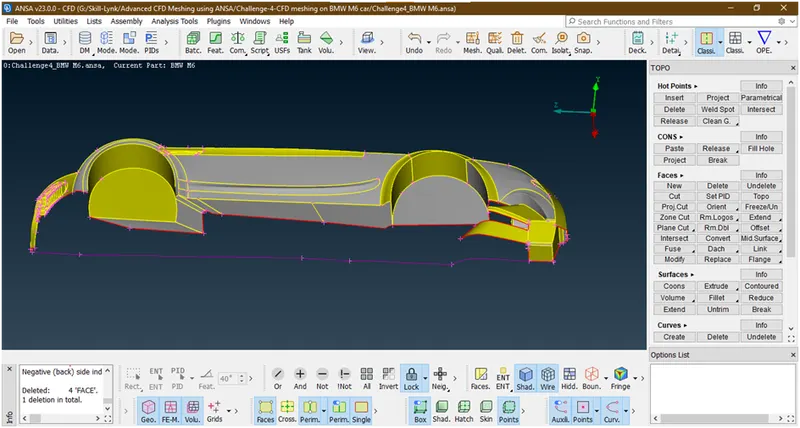
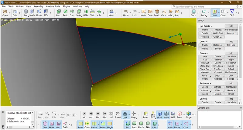
Let try to make surface here
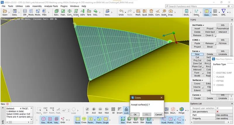
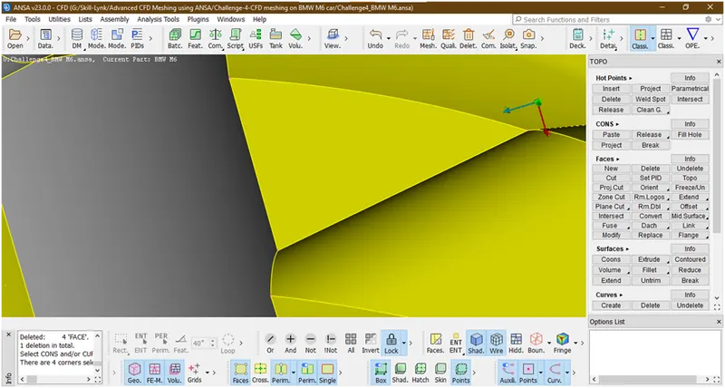
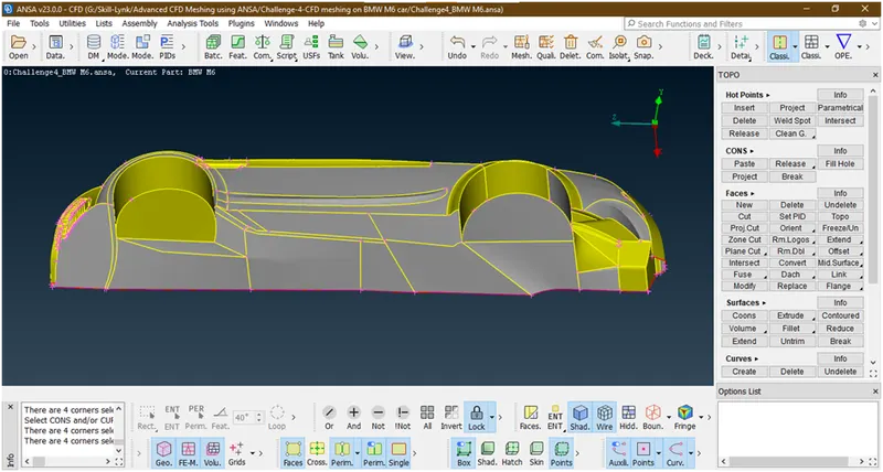
Now we have successfully clear the floor.
- Lets check for errors in this part is remained
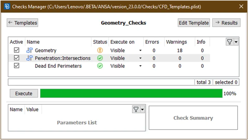
Now there is no interaction error so lets check what are the geometry warnings
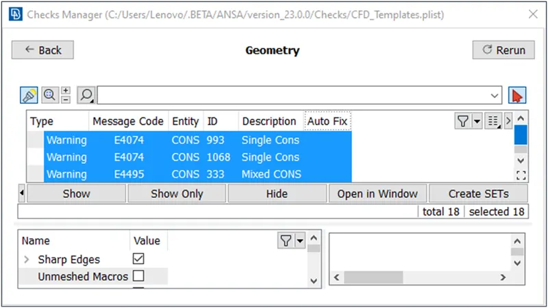
These are the singlre cons are due to half portion we have deleted.so as of now we ignorng these.
- Now lets delete the curves.for that goto delete under curves
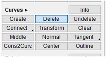
Now select the curves which we have created
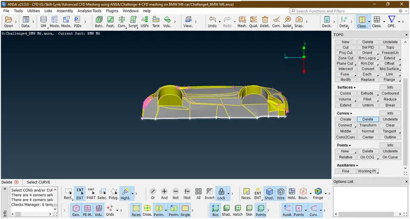
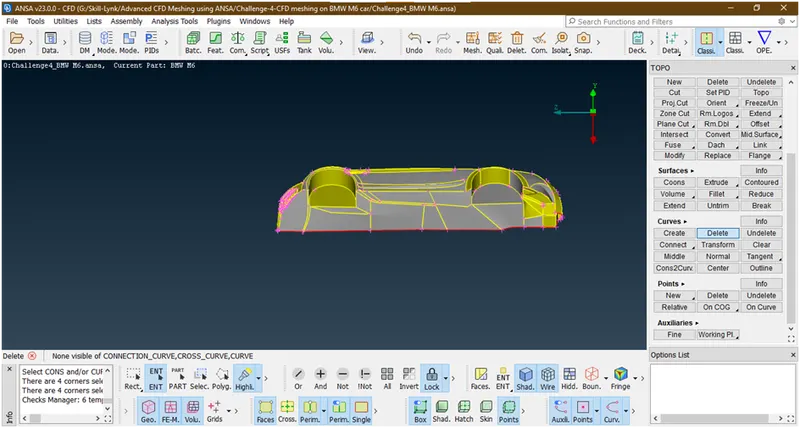
Now remove the lock and click on all.
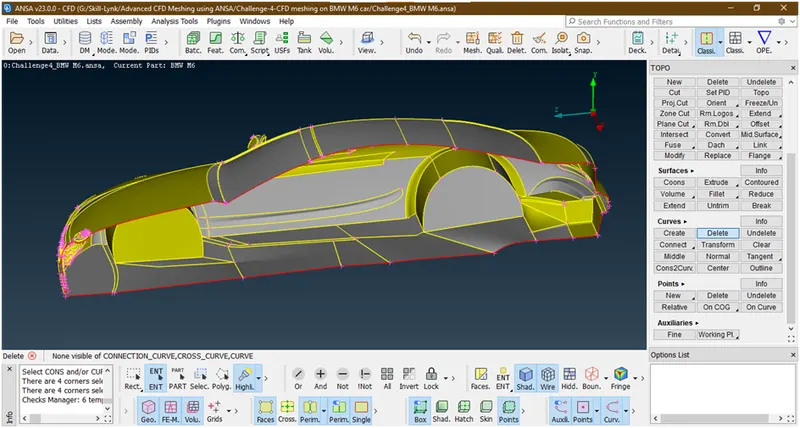
20. Now lets check for errors
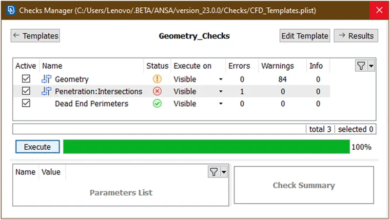
Let see where this intersection error occurred
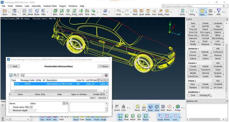
This occurred in tyres only.so lets see and removed this.
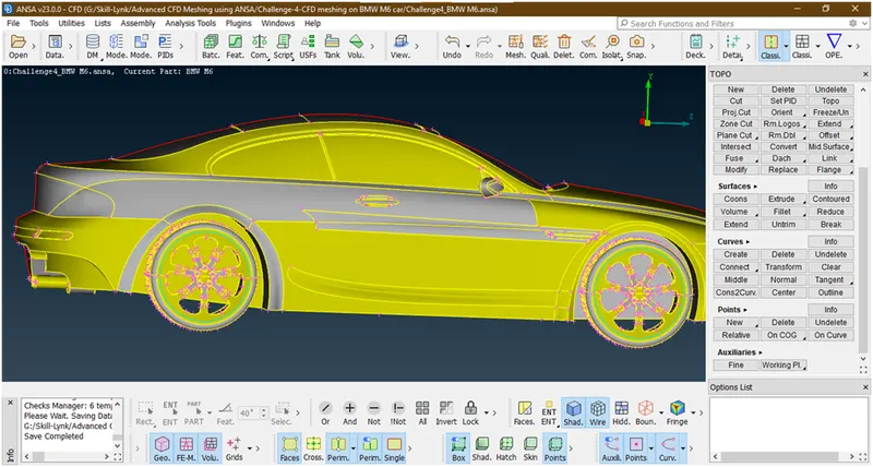
Some triple cons are also shown in tyres.
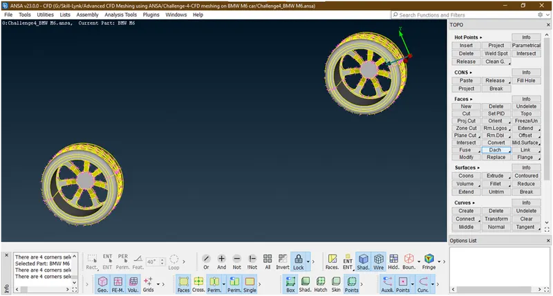
- Let hide all other parts and concentrate on tyres by using inot tool and pid selection mode

First select tyres and rim
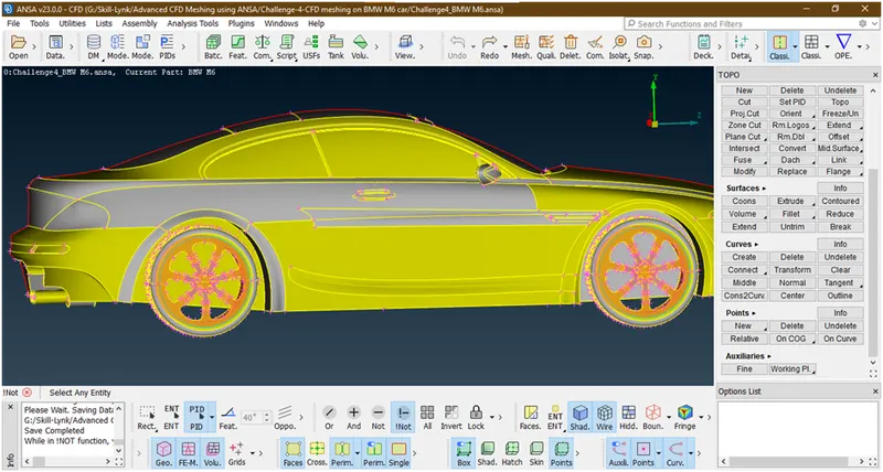
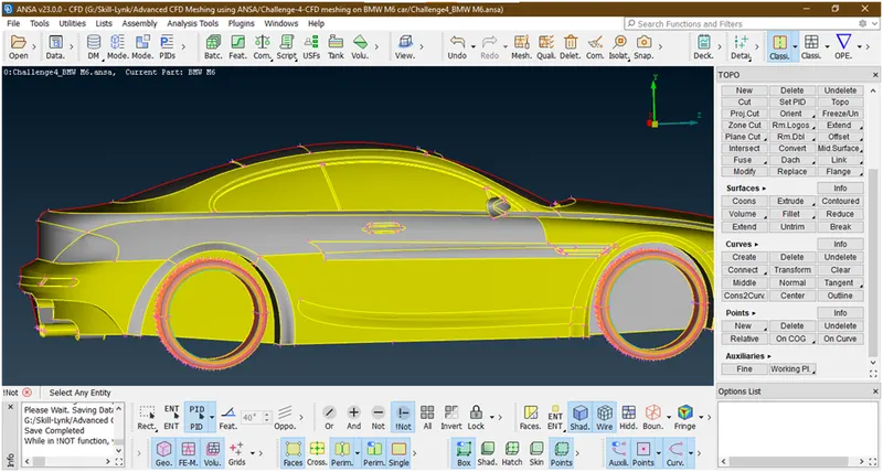
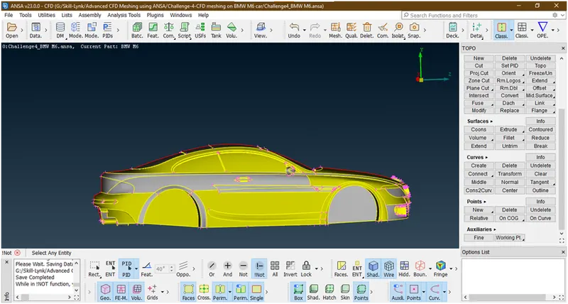
Then hit the middle click now all the body is hide and only tyres shown.
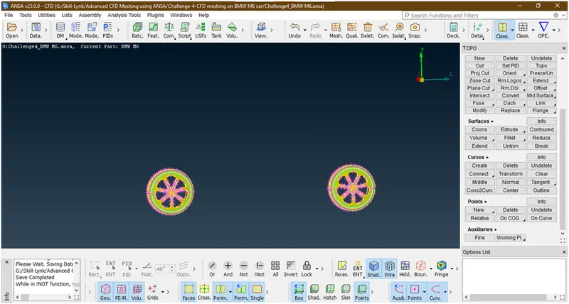
Done.lock it.
- Let see first tyre and rim
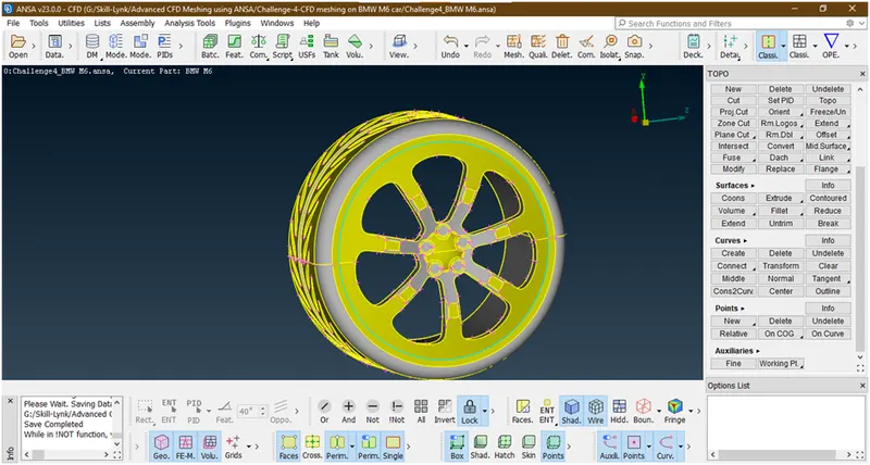
Let hide this
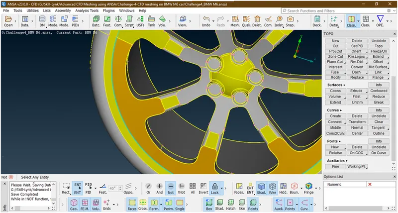
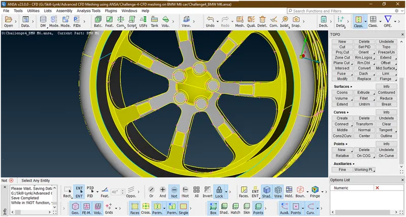
There is some triple con seen is due there are overlapping surfaces so we will delete these overlap surfaces.try to delete this suraface
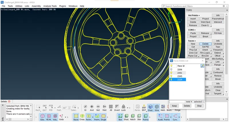
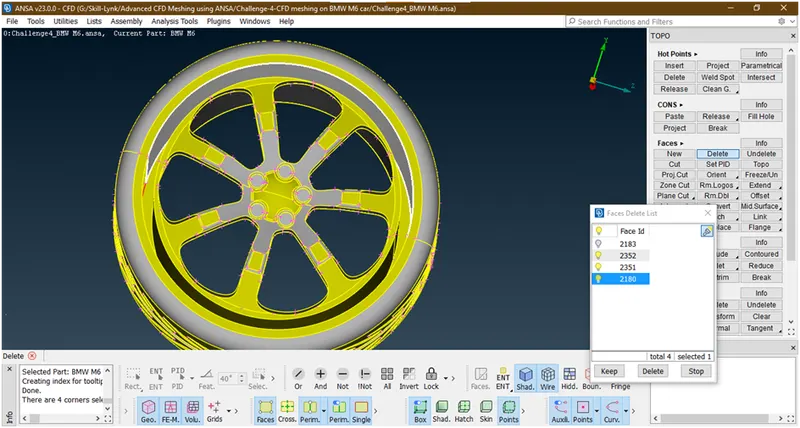
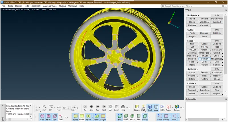
Now we have deleted thes overlapping surface but this causing a single con
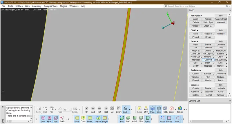
So lets make surface there
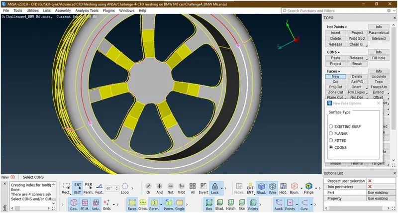
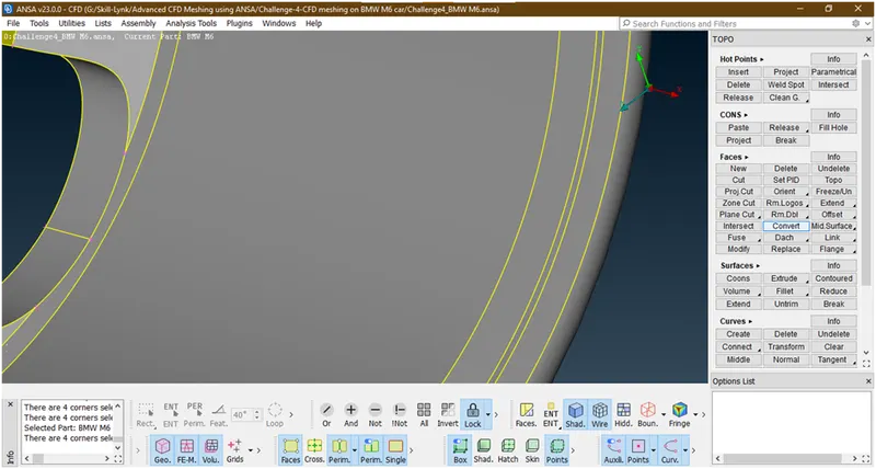
Now similarly we will create a surface on remaining half portion
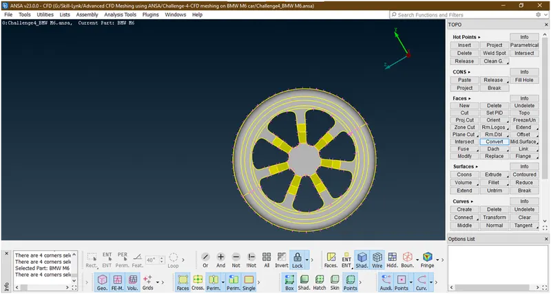
Now we have created the surface there.
- Do the similar procedure for other tyre also.
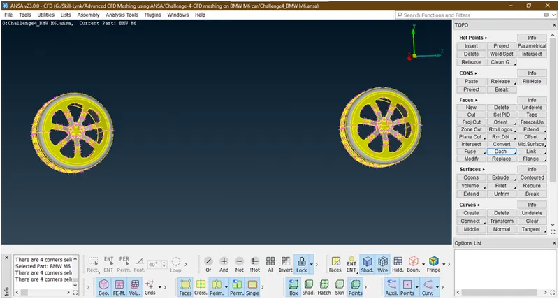
- Let check for any errors in thiese tyres
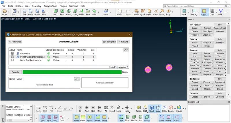
Now we have removed all erros .
21. Now click on all
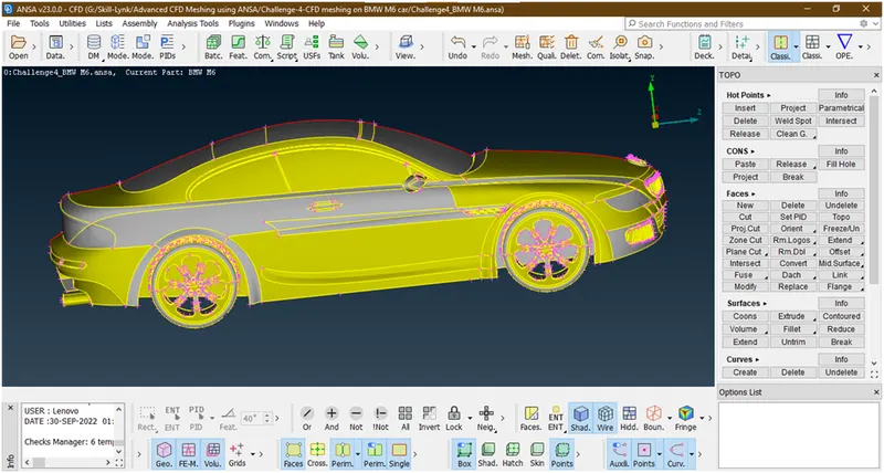
Now again check for any errors remaining
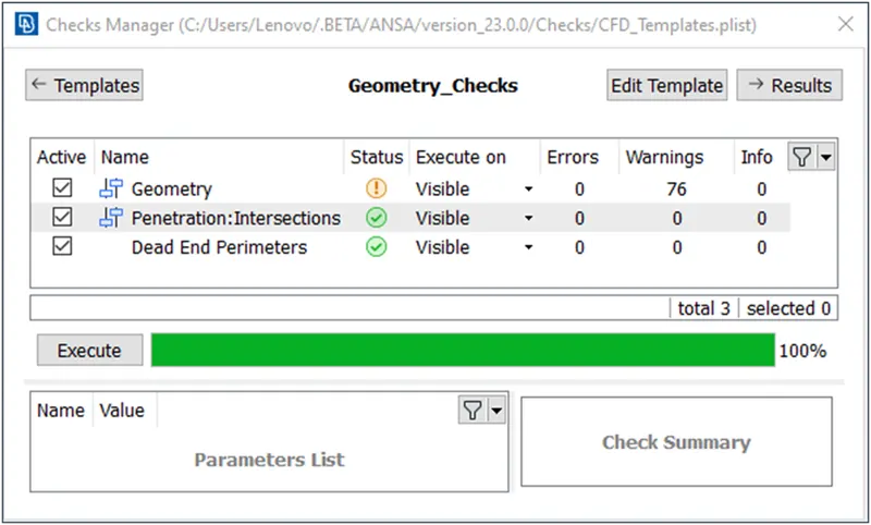
Now we have succesfully removed all interaction erros. Let see what the geometrical warnings.
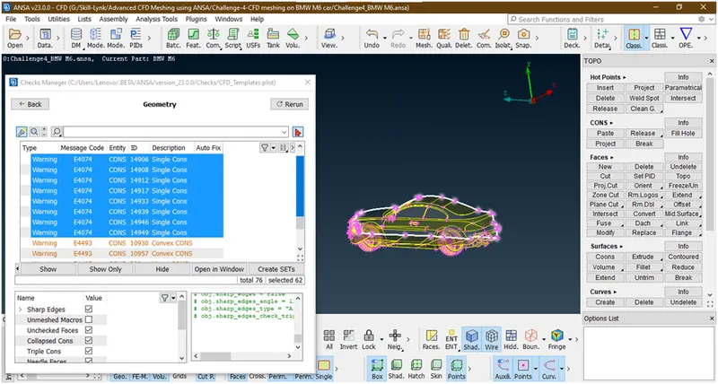
These are some single part at boundry where we have deleted half portion so right now we are ignoring.
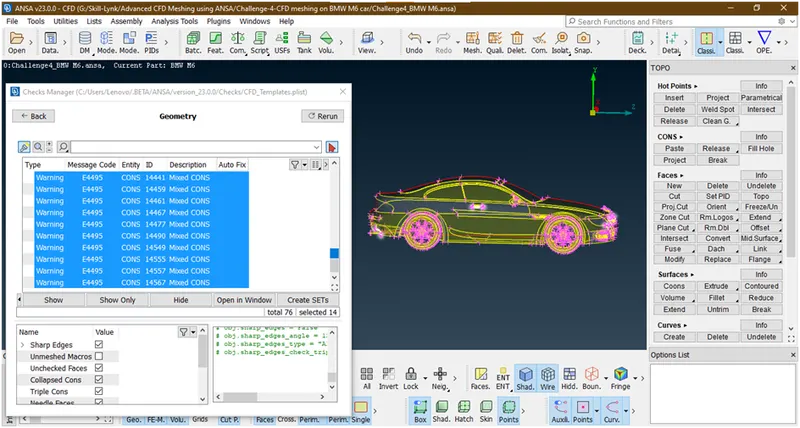
These are some concave con,conves=x con,mixed cons which are due to shape of geometry so it can’t be removed so we are ignoring this.so we have removed all errors.now assign pid to each part.
22. Let hit an topo to autofix if some errors are created during geometry cleanup.
23. Now delete extra hotpoints if created.
24. Lets assign pids
- Goto pid manager
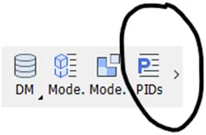
When we click on this the new popup opens
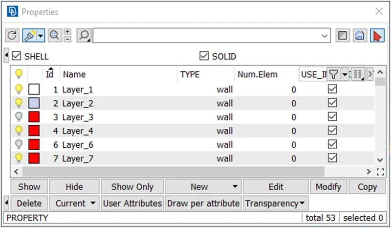
- Let create and assign logo
Let hide all other parts and show logo by using not tool and pid selection mode
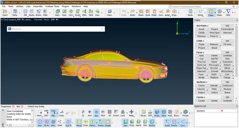
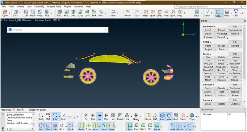
Goto set pid under faces
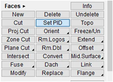
Now select the faces
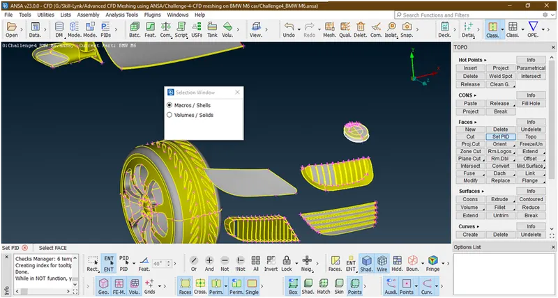
Hit the middle click then new popup opens
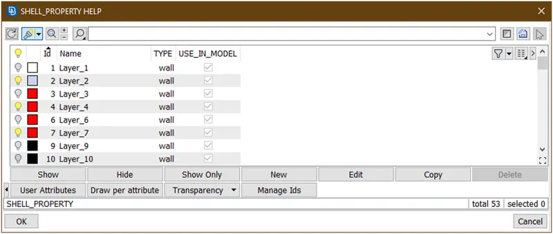
Now click on new,again a new popup opens
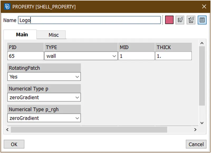
Now rename this and click on ok, the pid will create.
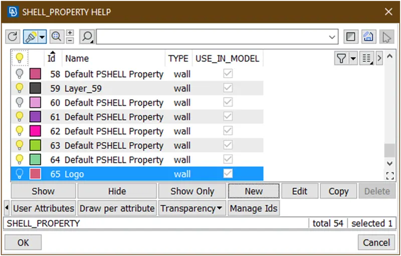
To assign this double click on this.it will assign.
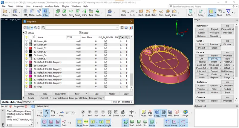
Follow the similar procedyre for all other parts.
- Let assign silencer
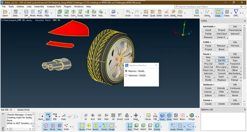
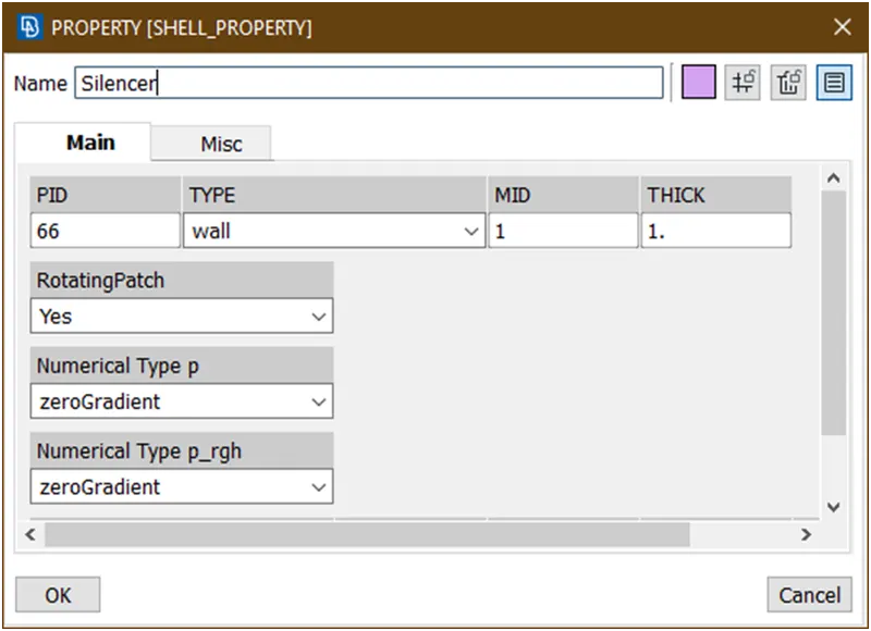
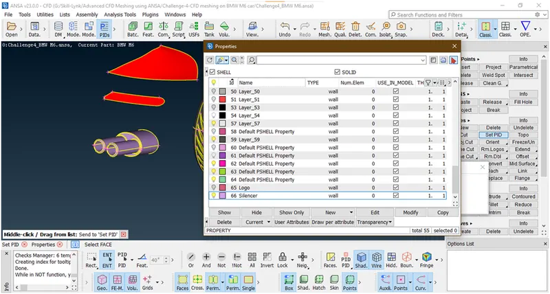
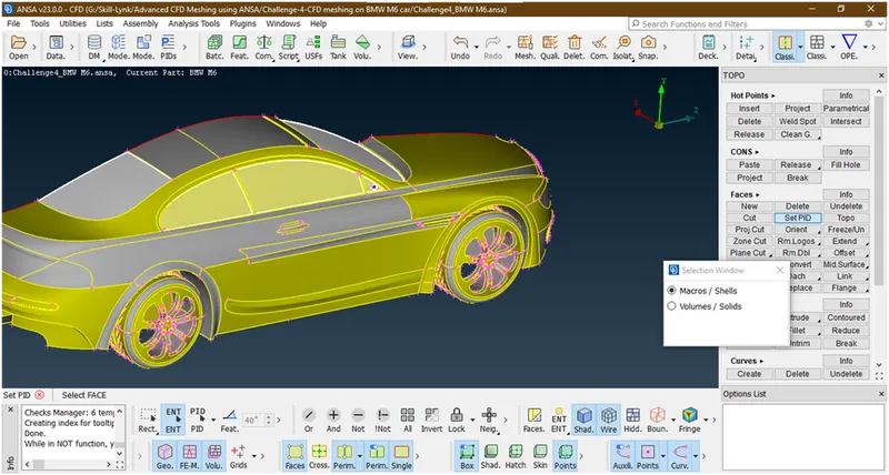
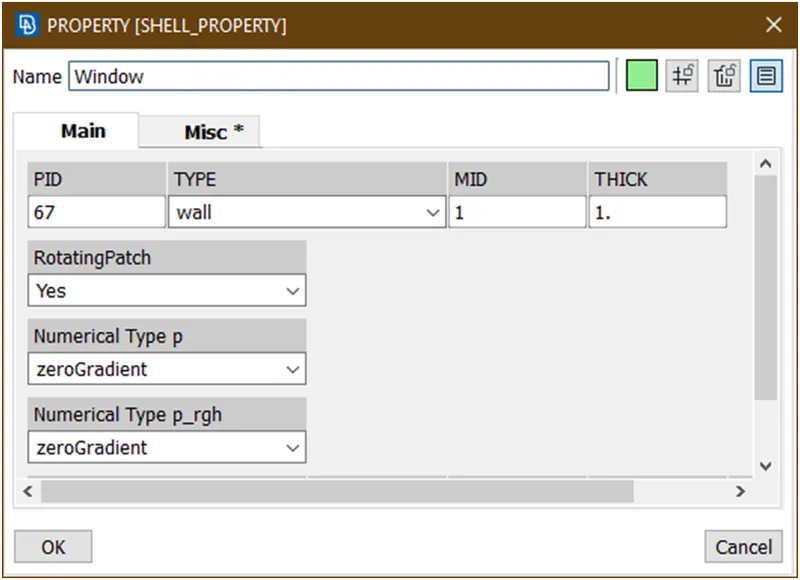
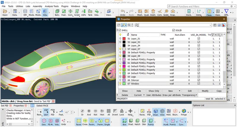
- Let assign window
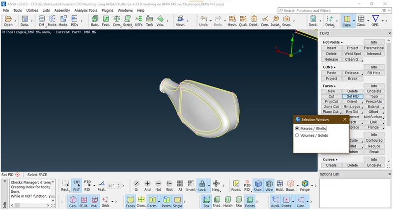
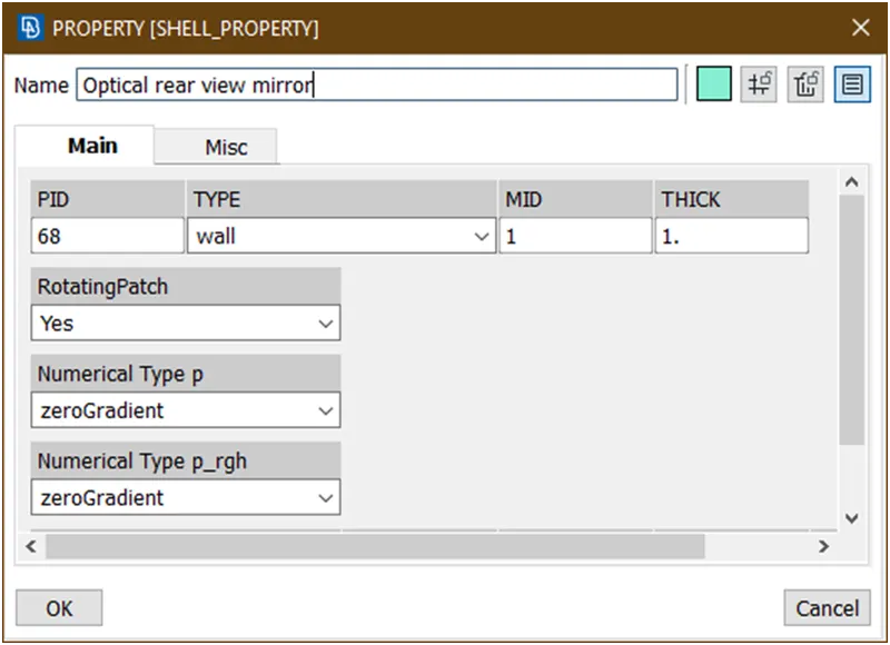
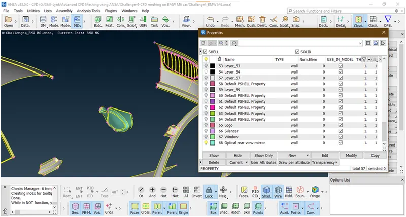
- Lets assign optical rear view mirror
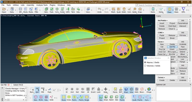
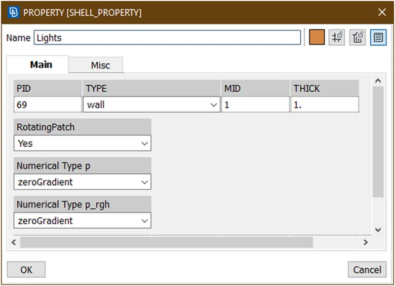
- Let assign lights
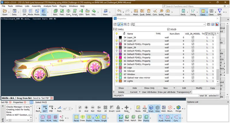
- Let apply rim and tyres
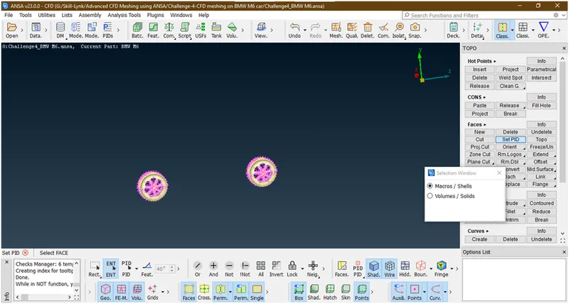
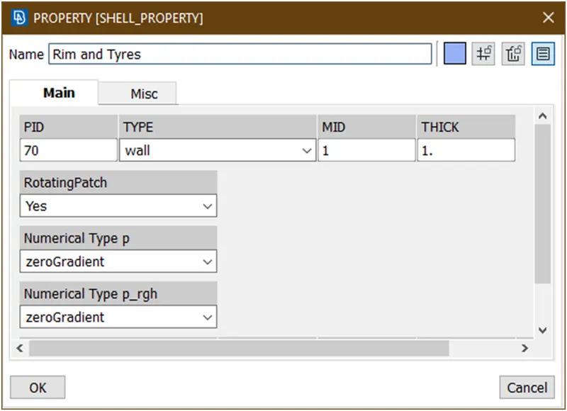
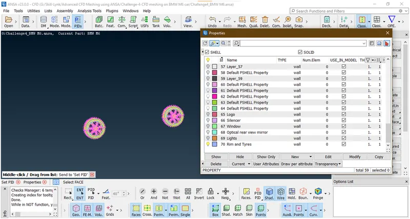
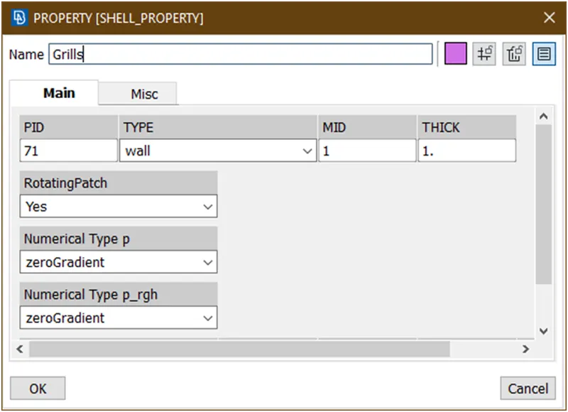
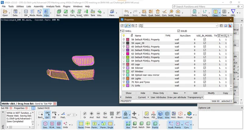
- Let assign grills

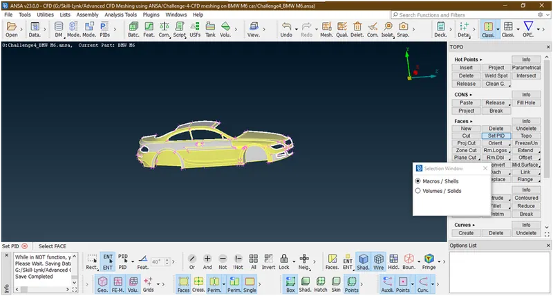
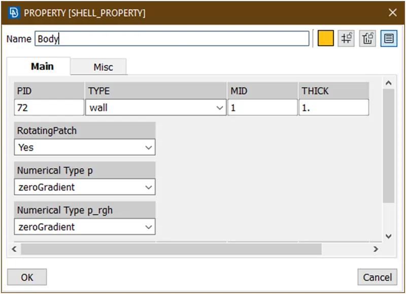
- Let assign Body
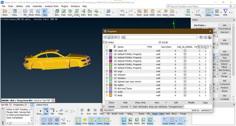
- Lets check all parts are assign or not
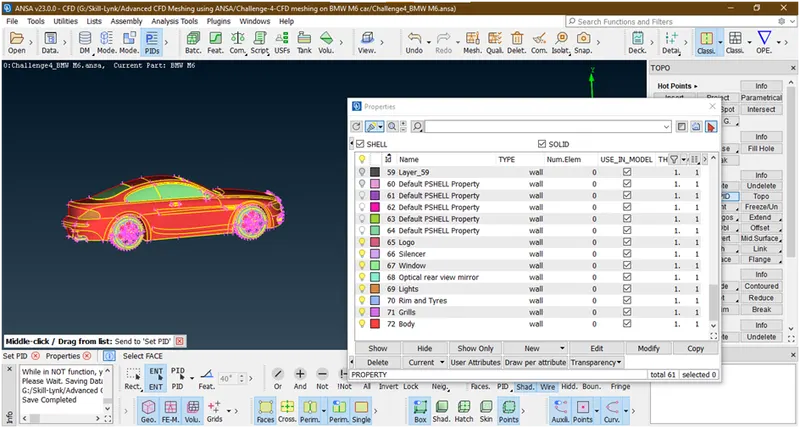
- Now we have successfully created and assign all pids which are required.now try to delete these files from pid manager
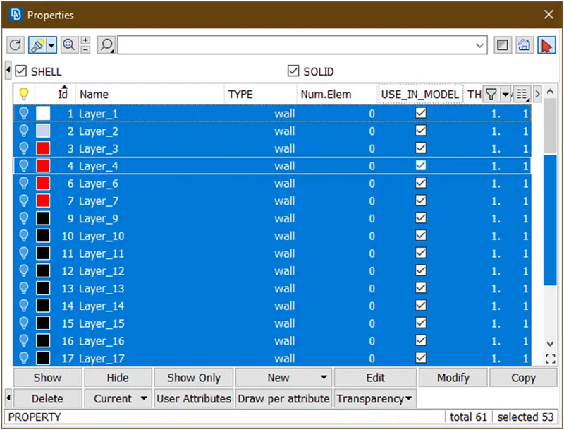
But these are not deleted so lets use compress tool

A new popup opens
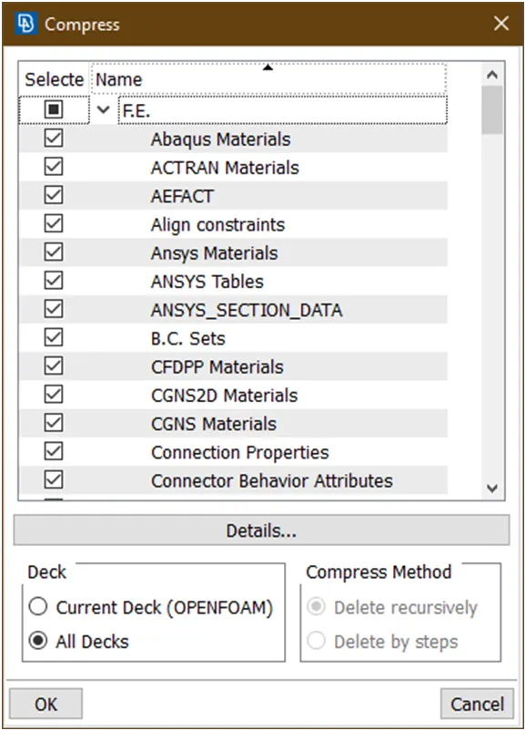
Just click on ok the files will delete
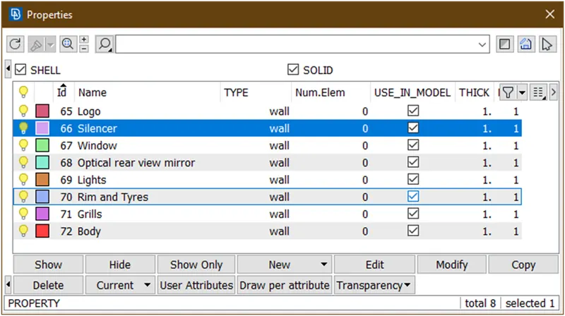
Now we have successfully cleared all geometrical errors .now we are able go for meshing the surfaces.so lets go for surface mesh.
3. Surface Meshing of car :
- Now goto the classic mesh
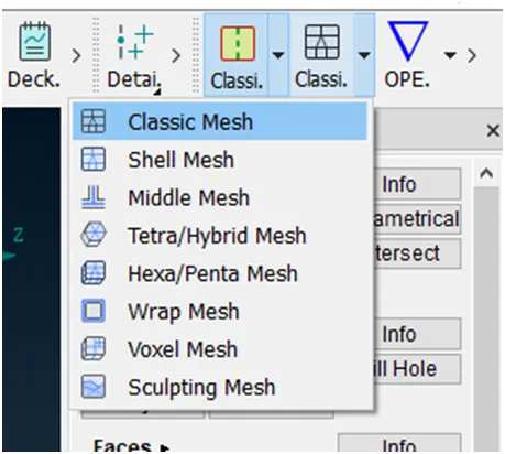
- The user interface looks as
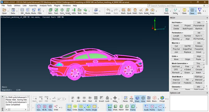
- Target lengths for the different parts of a model are as follow:
- Body = 3 mm
- Lights = 4 mm
- Grills = 1 mm
- Rims and Tyres = 2 mm
- Optical Rear view mirror = 2 mm
- Window = 2 mm
- Silencer = 3 mm
- Logo = 1 mm
- 2D Element type = Tria
- 3D Element type = Tetra
2. Lets apply uniform quality criteria to while car part
- Goto quality parameter

- A new popup opens
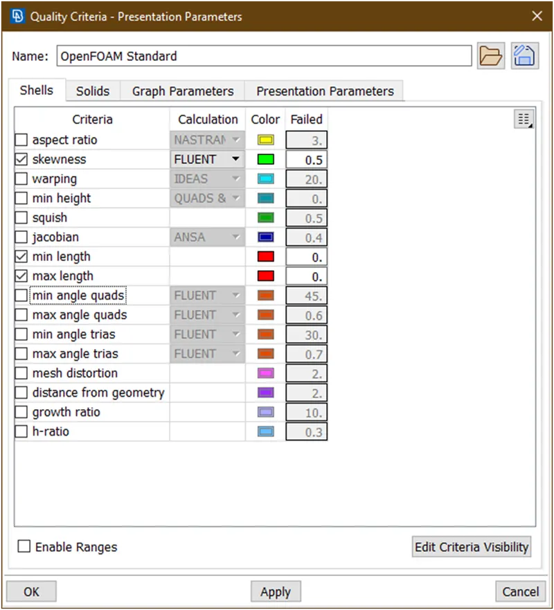
Now here enabled skewness,minimum length and maximum length.
Now remove all other quality checks parameter. For that goto edit criteria visibility a new popup opens
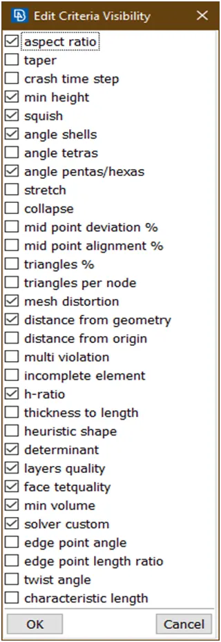
Now unchecks all other parameters and click on ok
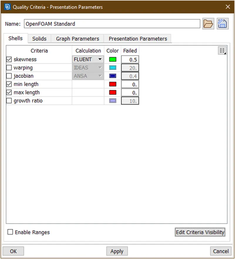
Now click on apply and then click ok.
- Now click on this to show quality criteria in geometry
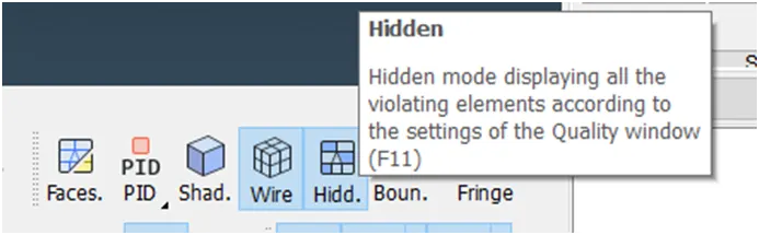
Now it is showing
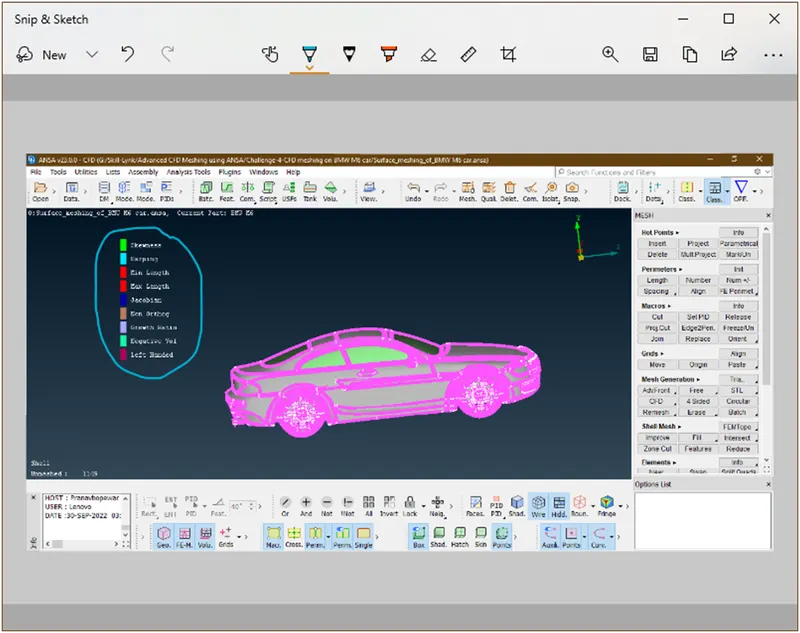
Just click on the parameters which we don’t want
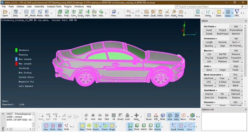
We have done off these criteria.now right click on this
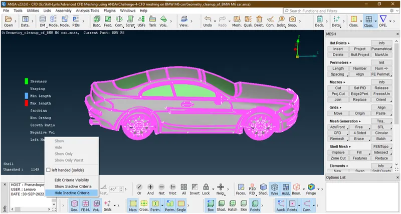
Click on hide inactive parts
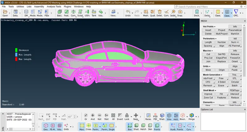
We have enable the parameters which are required.
- Now here the minimum target length= 1mm and and maximum target length=4mm. so lets goto the quality parameter and give universal values of parameters
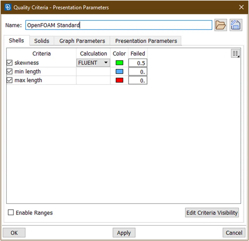
Now put values as
- Skewness = 0.5
- Min length = 0.1
- Max length = 8
Now click on apply then click on ok.we have successfully gives qulity criteria
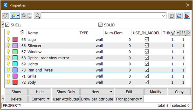
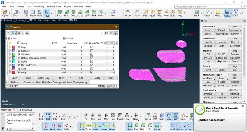
3. Let mesh logo and grills
- Goto pid manager and hide all other parts and enable only logo and grills.
- Let goto mesh parameter

A new popup opens
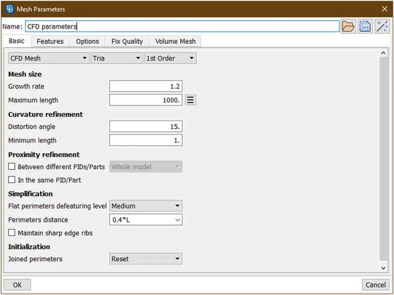
Here the target length=1 given. So give minimum length=0.5 an max length=1.5
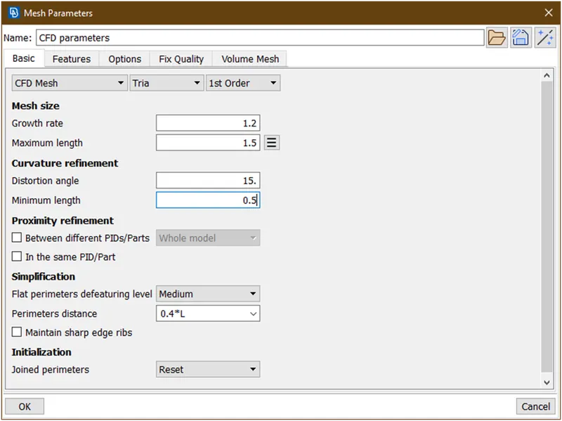
Now click on ok.
- Now goto length under parimeter
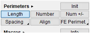
Now select perimeter->select the faces

Hit the middle click, a new popup opens
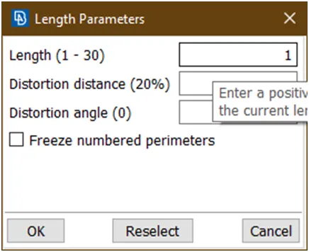
Give the target value=1 then click on ok.
Now select the macros and select the faces
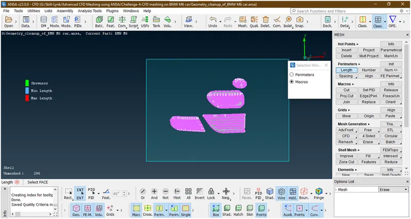
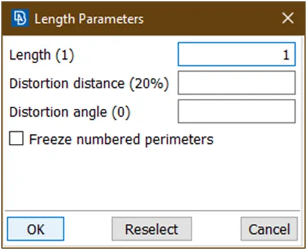
Hit the middle click, a popup opens
Click on ok.
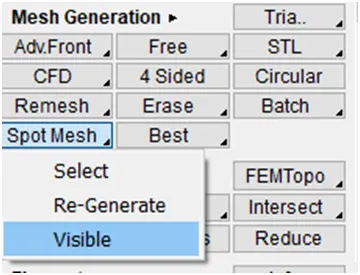
- Now goto mesh generation->spot mesh->visible and wait until mesh to be done
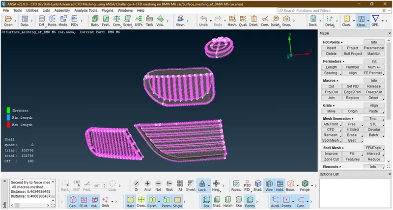
Here 180 elements are showing off i.e. they are failing so we are going to reducing this off elements=0.Now right click on this off
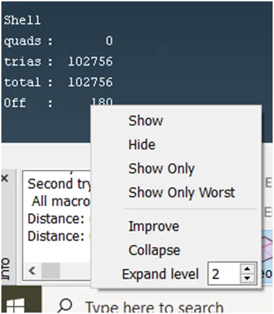
Goto show only and let check what are they
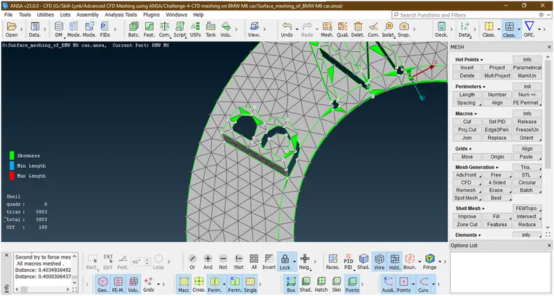
These all are failing to skewness .now click on all. then right click on off
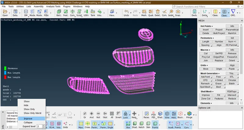
Then goto improve a new tab opens
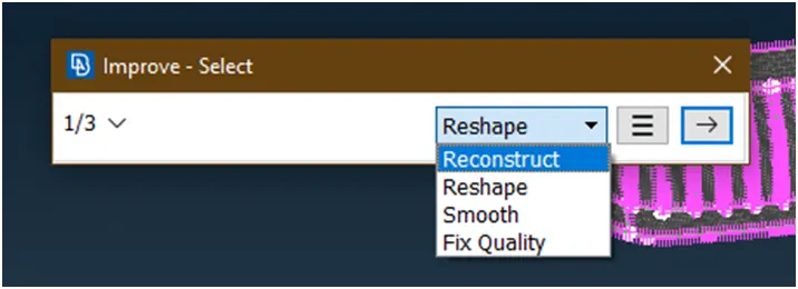
Apply reconstruct, reshape,smooth one by one to reduce the off elements and continued this process until the numbers has reduce to ‘0’,while doing this if off elements has been increased then stops there and do undo. for that select the parameters and click on this ‘->’ until last.
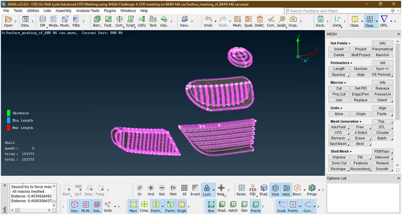
Now we have removed all off elements .
- Let freeze this.for that goto macros->freeze and select all faces
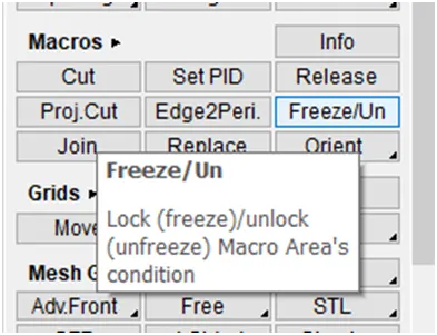
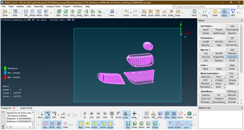
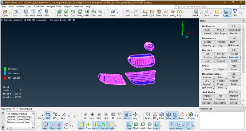
It has been frozen.
Do the similar procedure for all other parts.
4. Lets go for silencer
- Enable silencer by hide all other parts.
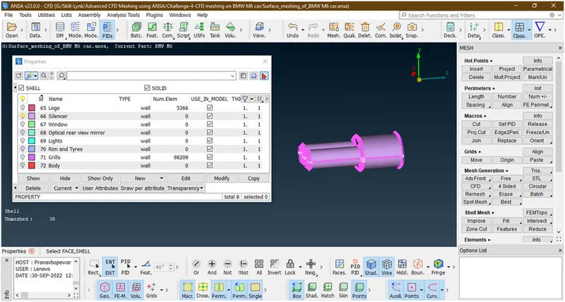
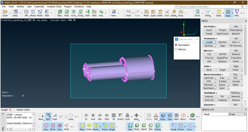
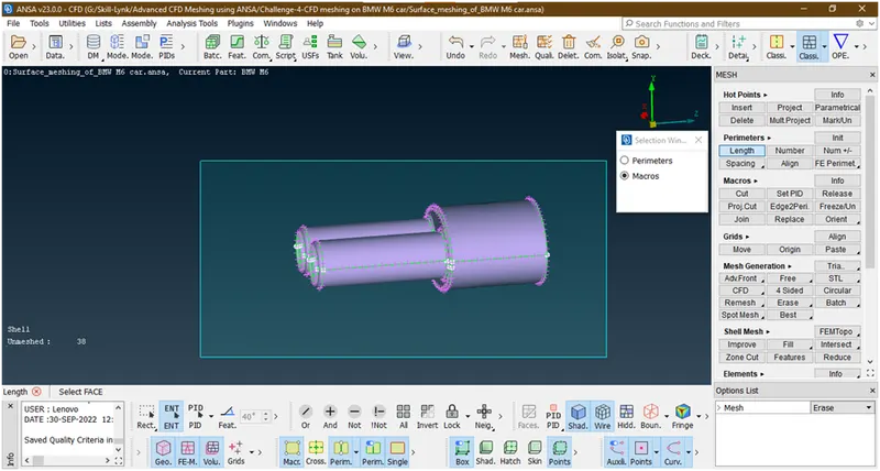
- Lets goto here the target length=3 so goto the mesh parameter and gives min length=2.5 and max length=3.5
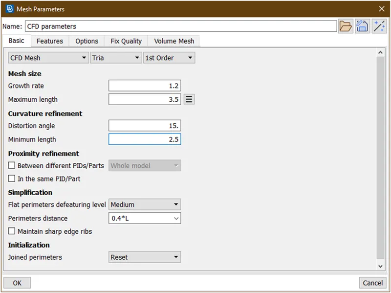
Now click on ok.
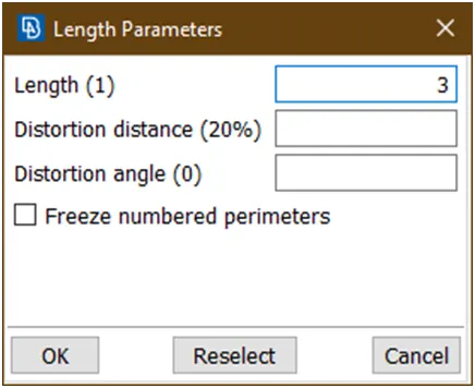
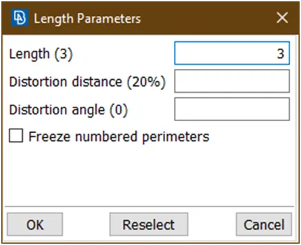
- Lets apply target length=3.goto length under perimeter and select total body and gives length=3 and hit the middle click then again goto macros select total body and give length=3
- Lets do meshing for that goto mesh generation->spot mesh-> visible->wait till meshing done.
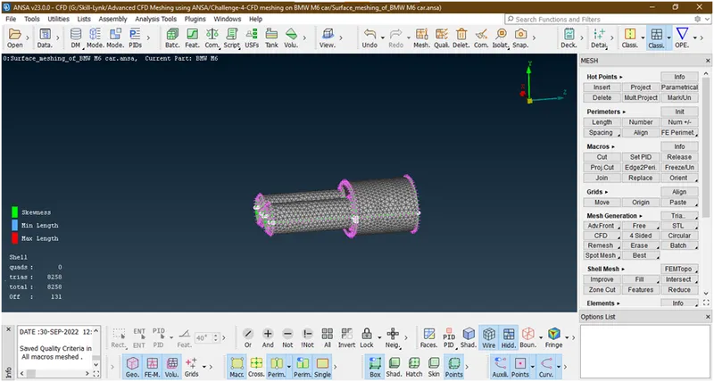
- Here 131 elements are off lets improve these by similar procedure as mention above.
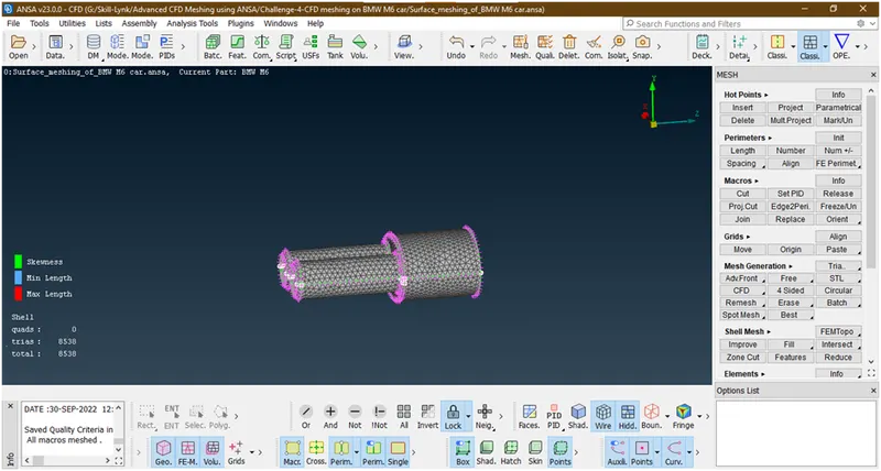
We have removed all off elements.
- Let freeze it
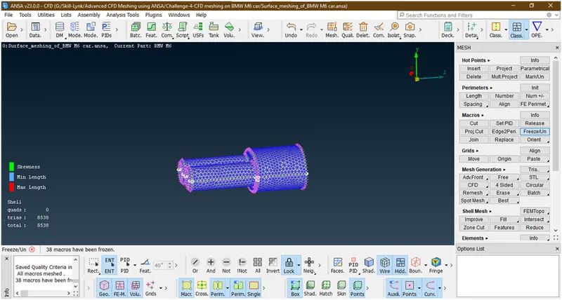
5. Lets go for rims and tyres , optical rear view mirror,window
- Let enable this by hiding all other parts
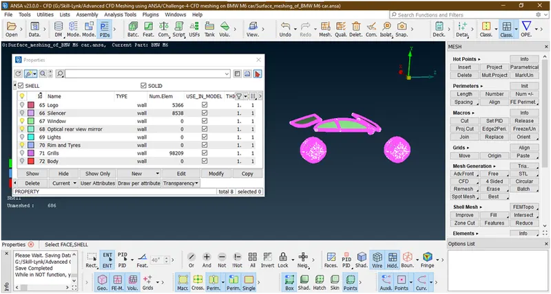
- Lets goto mesh parameter.here the target length=2 mm so we are giving min length=1.5 and max length=2.5
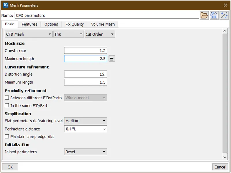
- Lets goto the length under perimeter and gives length=2
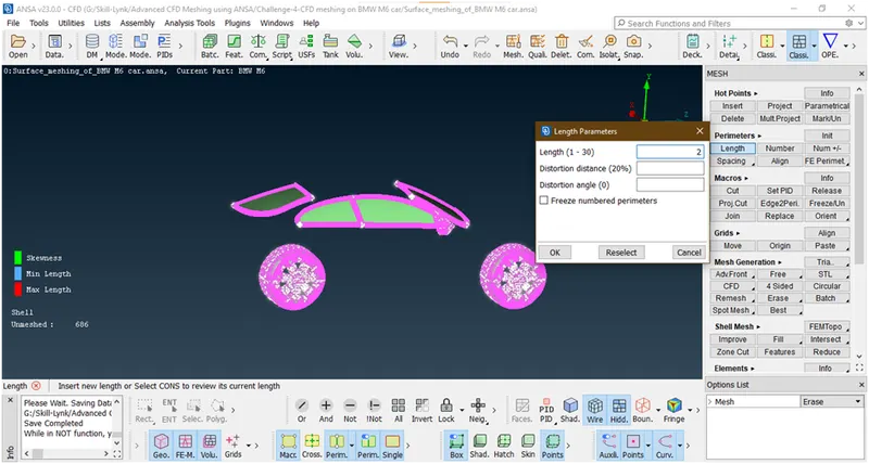
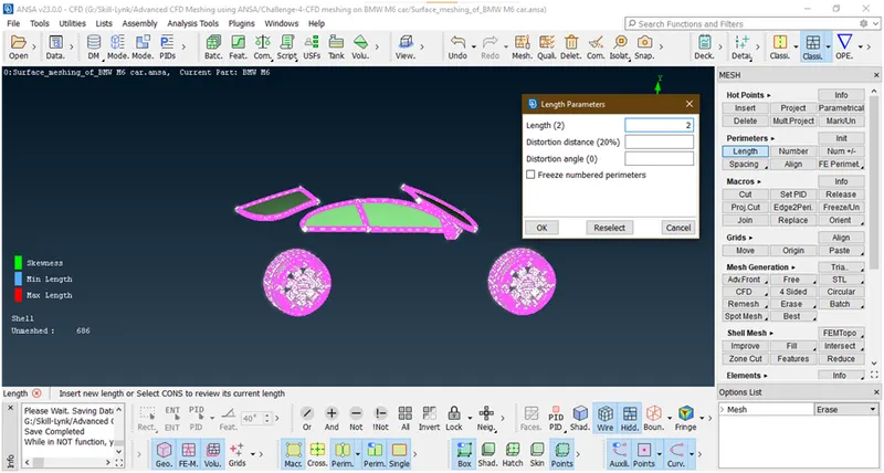
- For meshing goto mesh generation->spot mesh->visible
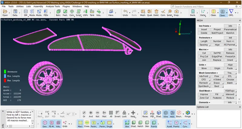
- Here 179 elements are off. lets try to improve mesh by similar procedure as mentioned earlier.
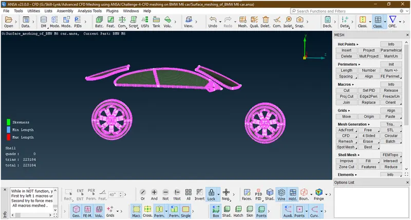
We have removed all off elements.
- Let freeze this mesh.
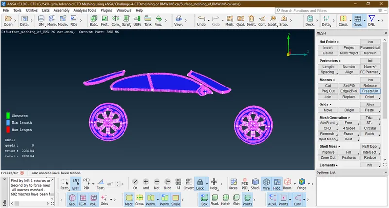
6. Lets goto lights
- Enable lights
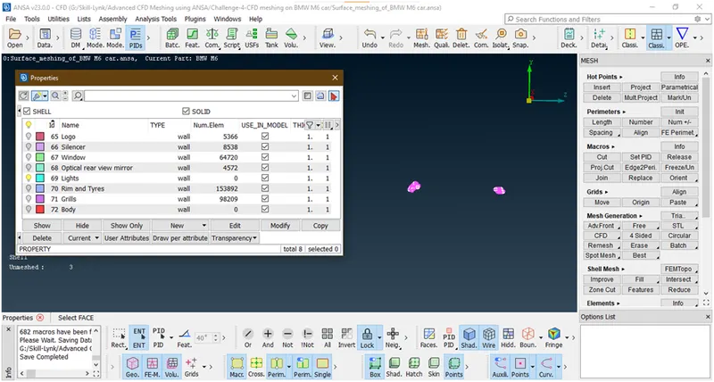
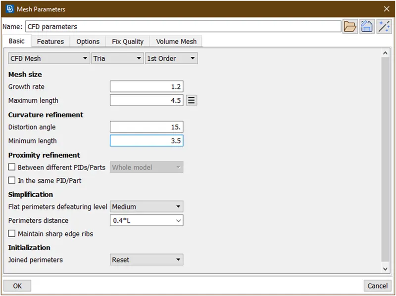
- Lets goto mesh parameters.here target length=4. So min length=3.5 and max length=4.5 we are giving.
- Lets goto perimeter->length for applying target length=4
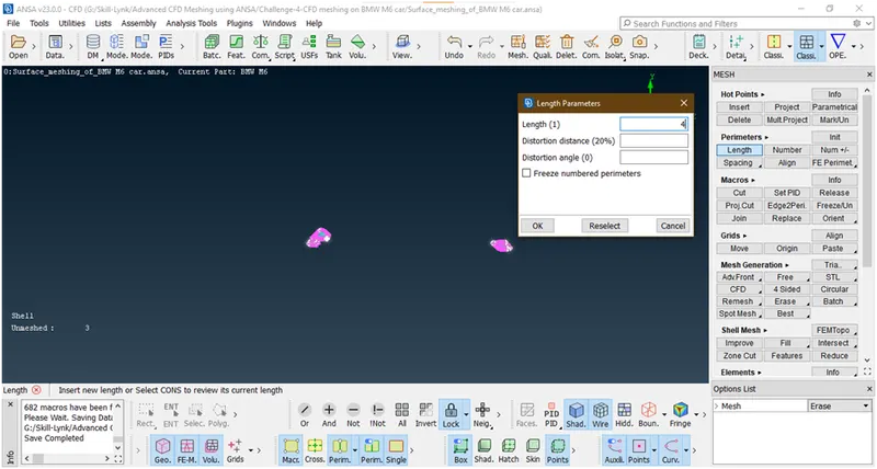
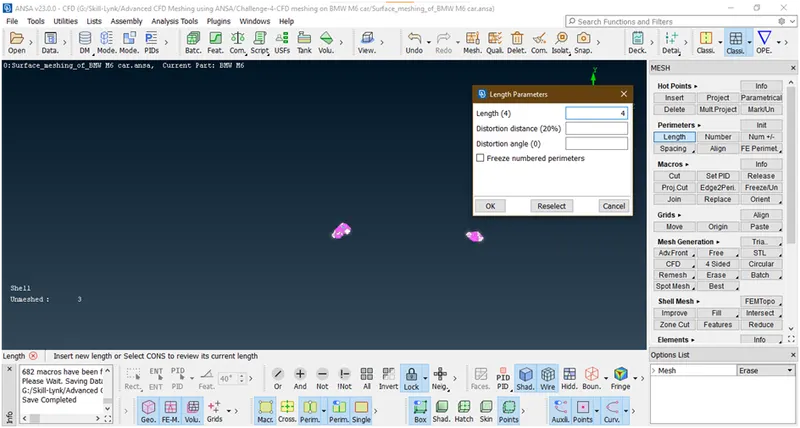
- Lets go for meshing.goto mesh generation->spot mesh->visible
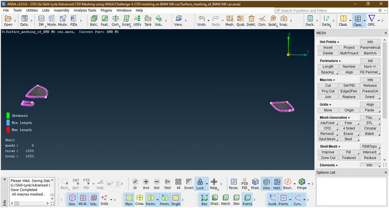
Here there is no any off elements .
- Let freeze this mesh
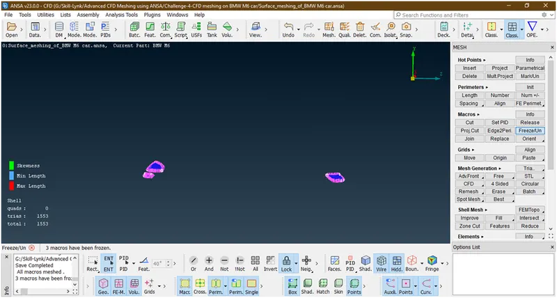
7. Lets go for Body
- Enable body
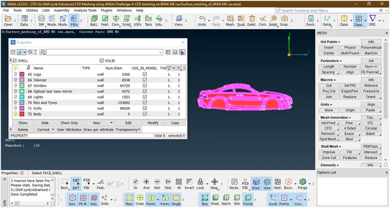
- Lets goto mesh parameter.here target length=3 so min length=2.5 and max length=3.5
- Lets apply target length=3. Goto perimeter->length and apply length
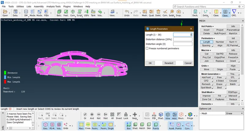
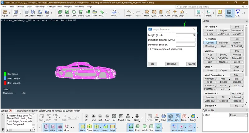
- Lets go for meshing. Goto mesh generation->spot mesh-> visible
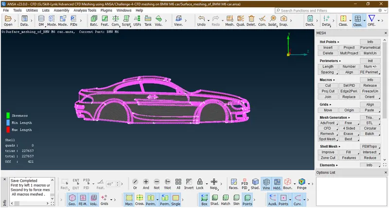
Now here 421 elements are off.
- Let try to improve these off elements by similar procedure
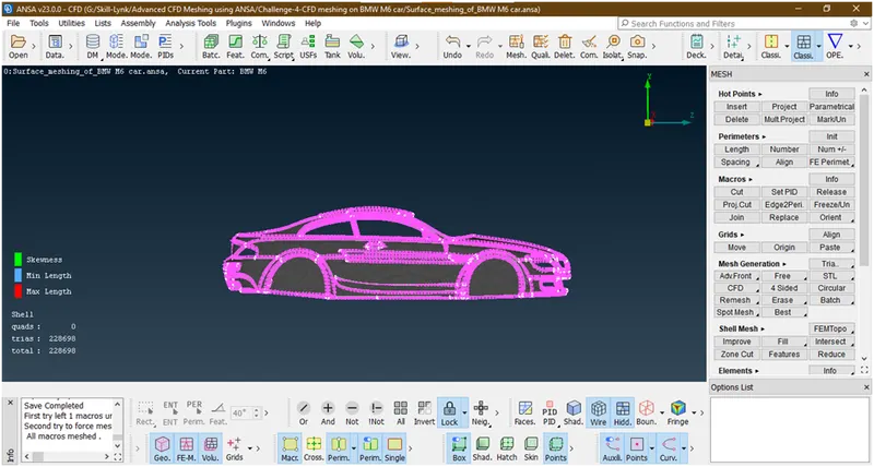
We have removed all off elements.
- Let freeze this mesh
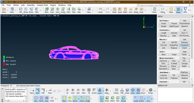
We froze all.
8. Lets click on all and review any part remained tobe mesh
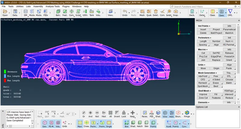
We have successfully mesh all half parts of a car with zero off elements.now we are able to mke a half portion.before going forward let unfreeze thee macros.for unfreeze select the total body with right key of mouse
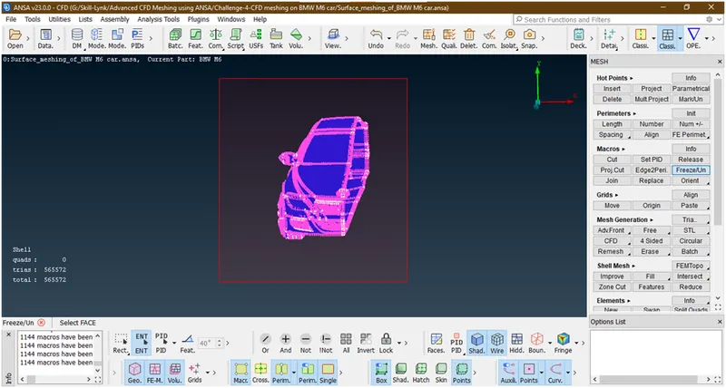
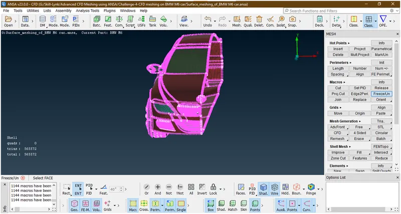
We have unfreeze the macros.
9. Lets create the half portion of car.so we are mirroring thehalf portion.
- Lets goto the topo mode
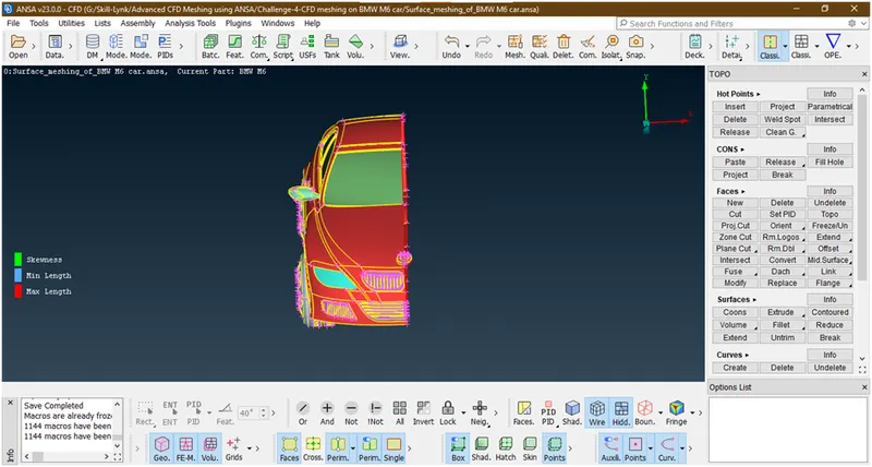
- First hide the logo because it is unique so cant be mirrored.goto pid manager and switch off the bulb off logo.
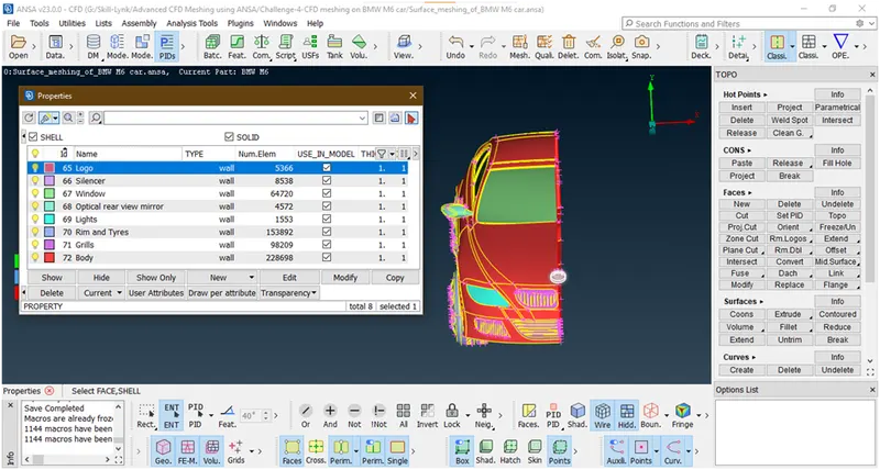
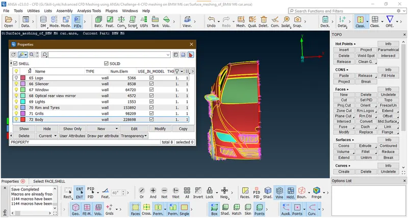
- Click on lock.
- Goto transform->copy
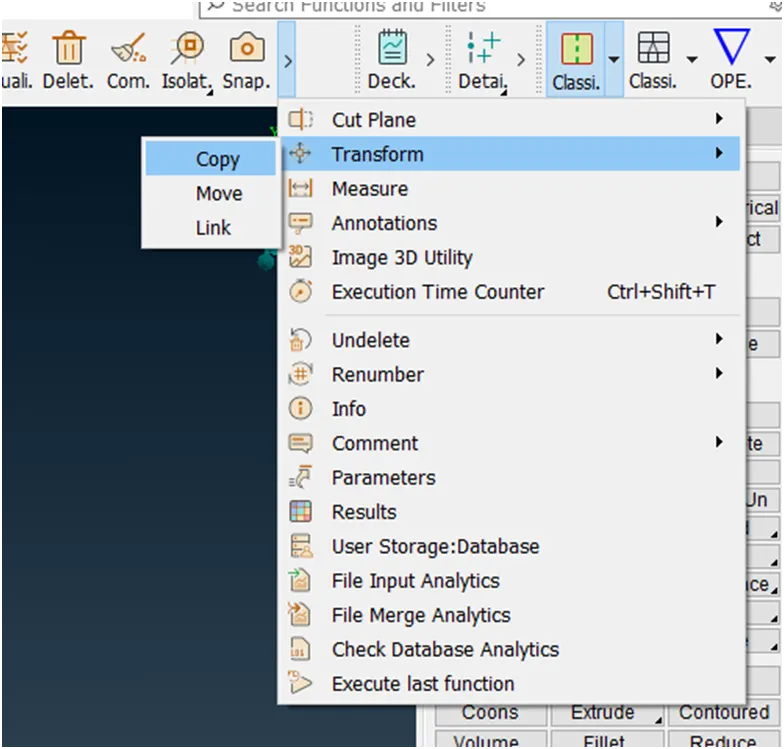
Now select the all faces.
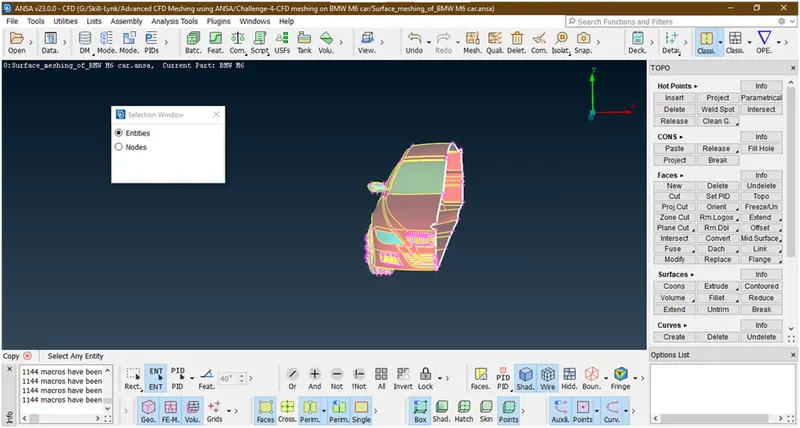
Hit the middle click, a new popup opens
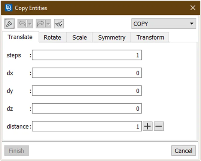
Goto symmetry->mirror 3 points plane
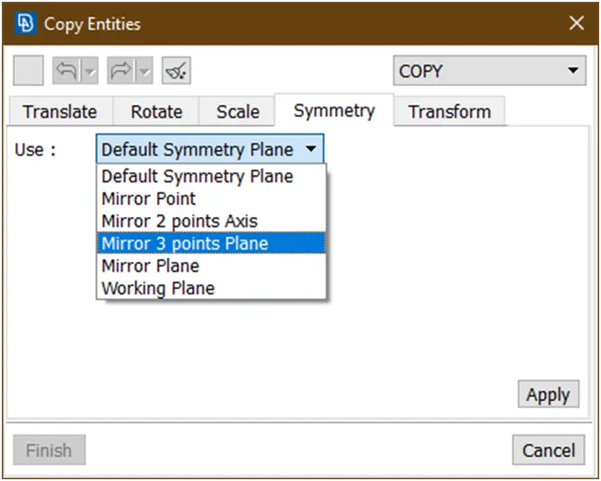
Now select any 3 points
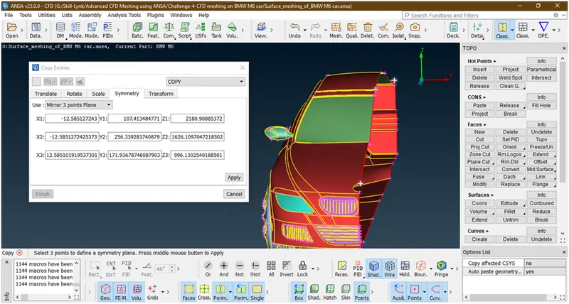
Click on apply, 1more popup opens
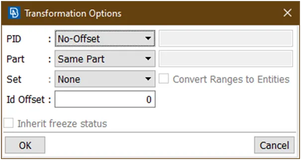
Click on ok
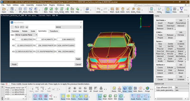
Click on finish
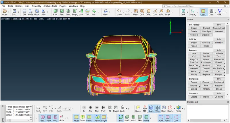
- Click on all
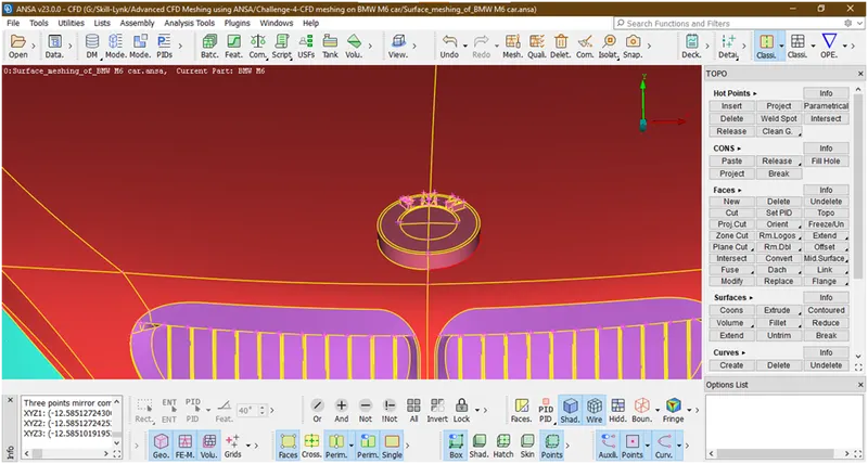
There is red con visible under logo so to remove this just project this con to the face.for that just apply topo there.
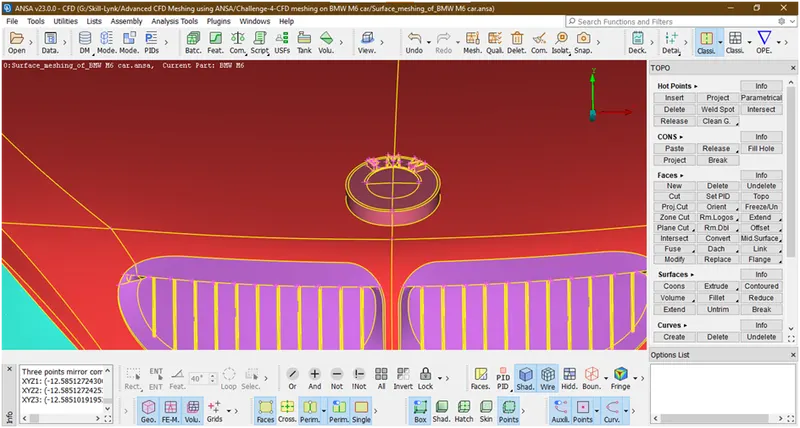
- There is a single cons seen in window
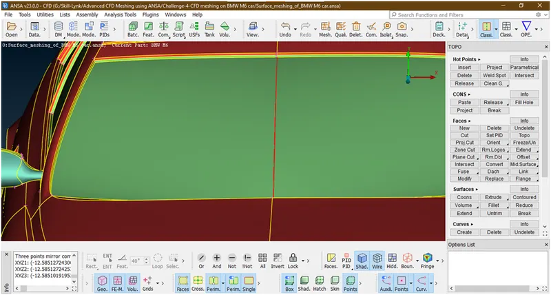
Let apply topo but it didn’t gone let check for errors
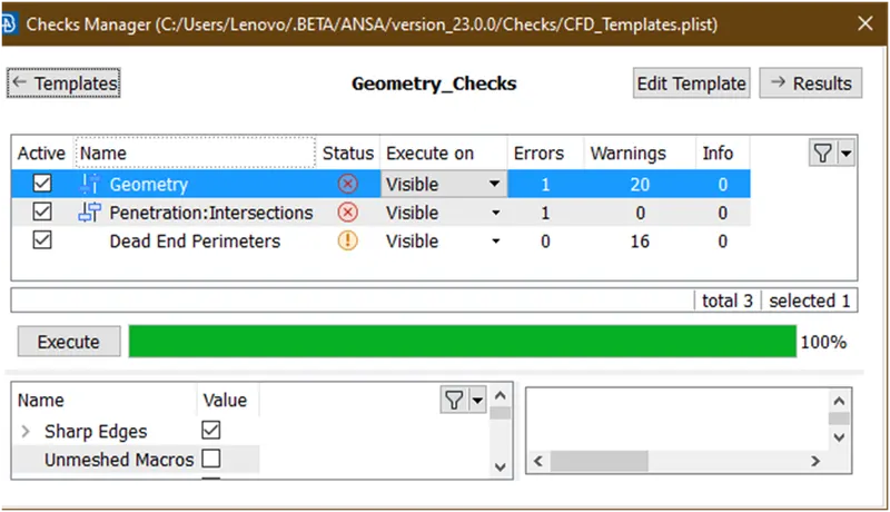
Let see where this single intersection error occurs.
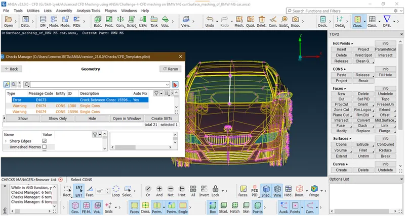
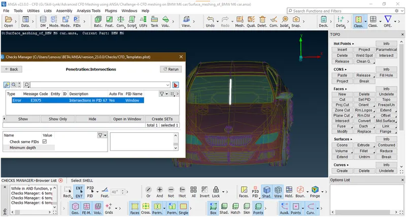
These are occurs at window.so let delete thes windows and recreate
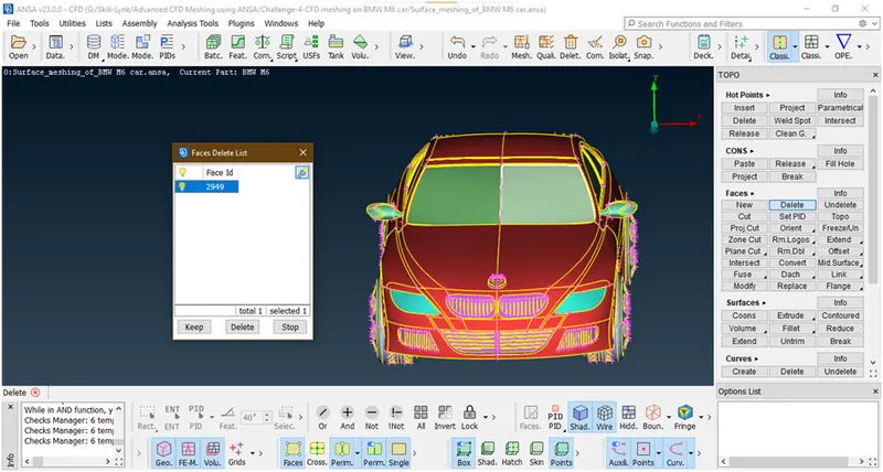
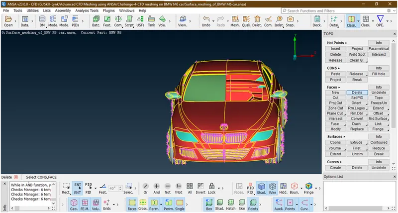
Now create the surface there
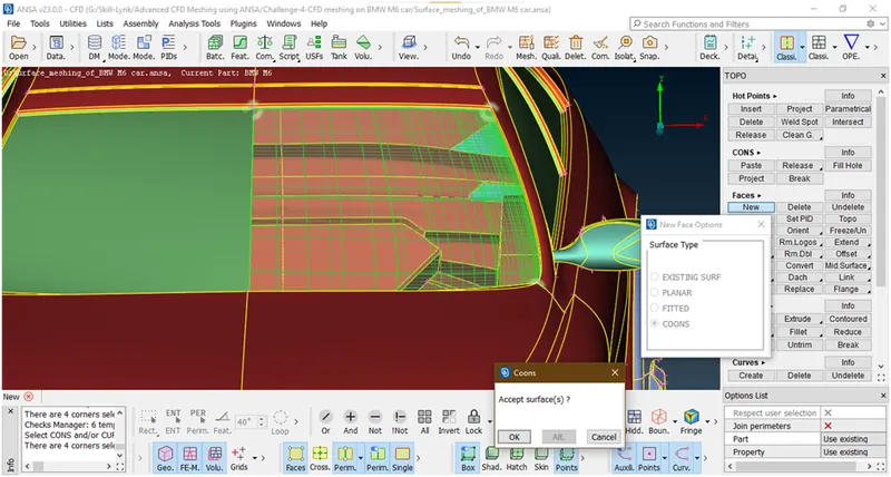
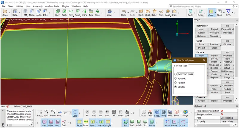
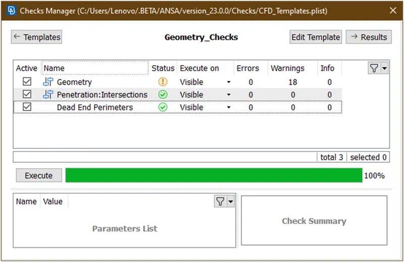
Let check for errors
Let see what are the warnings
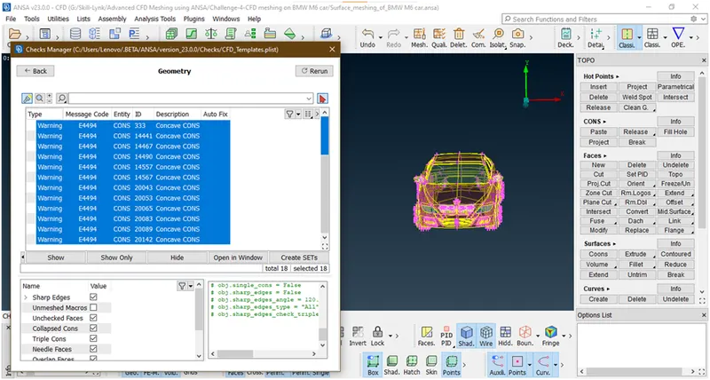
Now these are the warning as concave convex cons due to shape car so we are ignoring.
10. Lets goto classic mesh and see all parts are meshed or not
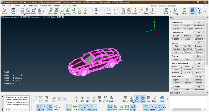
Some parts are unmeshed .so lets remesh all and freeze the part
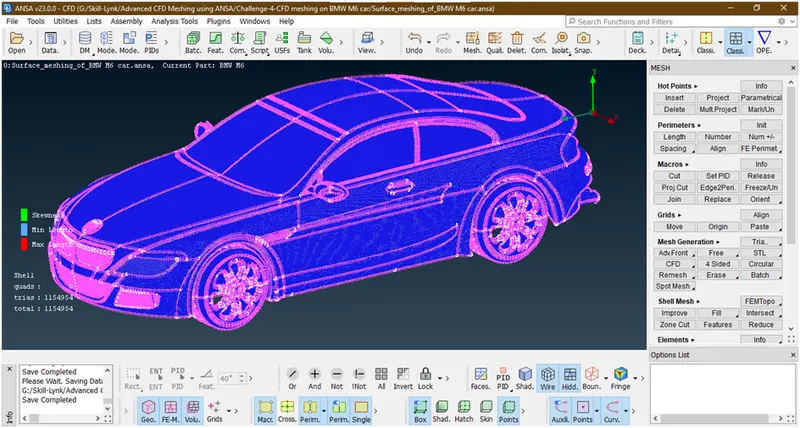
We have succefully created a cfd surface meshing of car. Now we will go for volume meshing. Now here we are doing an external flow analysis.for that we need a wind tunnel and do analysis inthis wind tunnel.so lets go for crating and surface meshing of wind tunnel.
4. Creating wind Tunnel :
1. Goto topo mode.
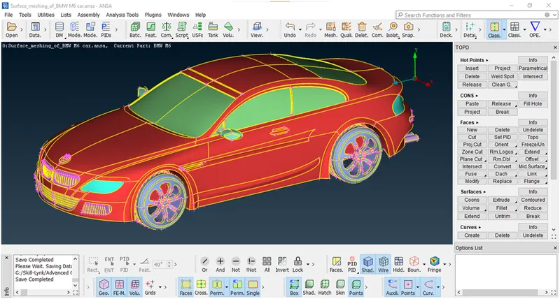
Here the wind tunnel is closed volume entity like room which is used for simulate the external flow analysis of air over a car.
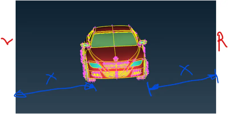
- Let,
Length of car = x
Front face at= 4x
Back face at = 6x
Top face at=3x
Bottom face = at convenient position that should not be intersect to the car
Left,right faces at = x
As shown in figure
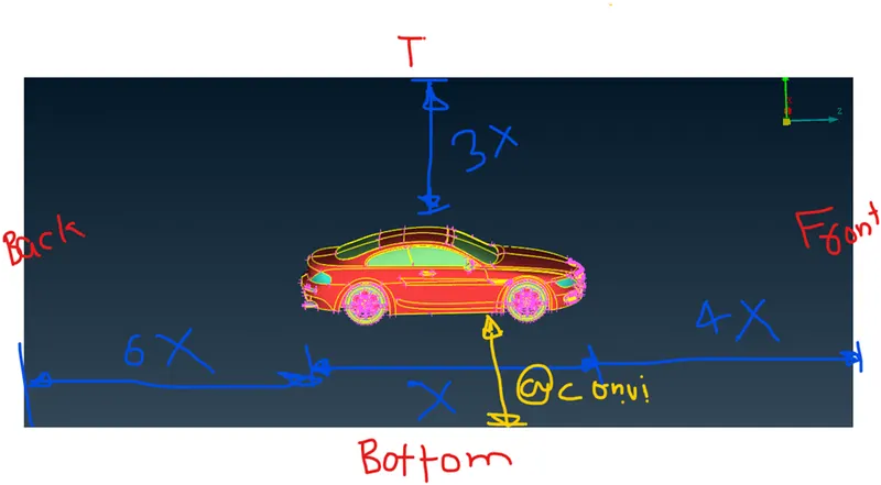
Lets start to create a surfaces
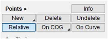
2. Let insert a point at middle from bottom side.for that goto relative under points.
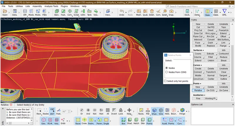
Now hit the middle key
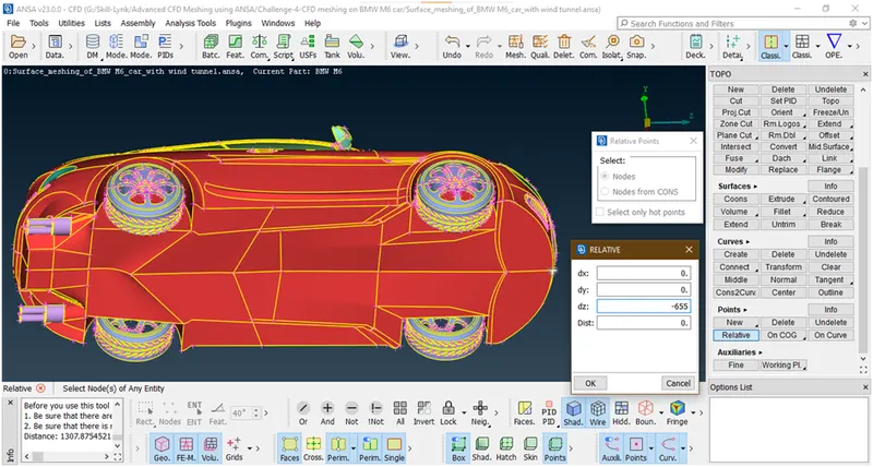
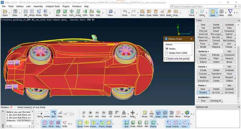
3. Now creates a points by taking reference of this point at a distance which mentioned above.
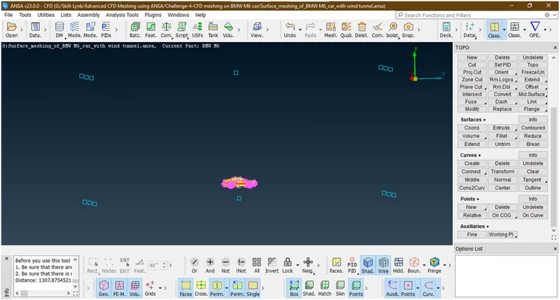
Now we have created all side points.
4. now create the curves between these points
- Goto curves->create-> select the points
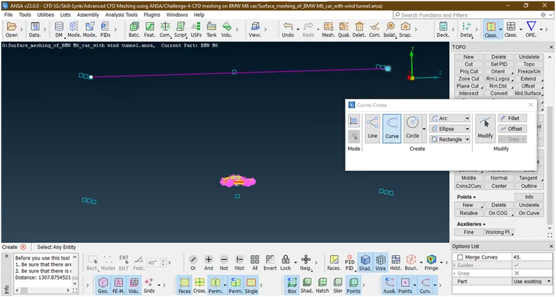
Similarly create curves between these points
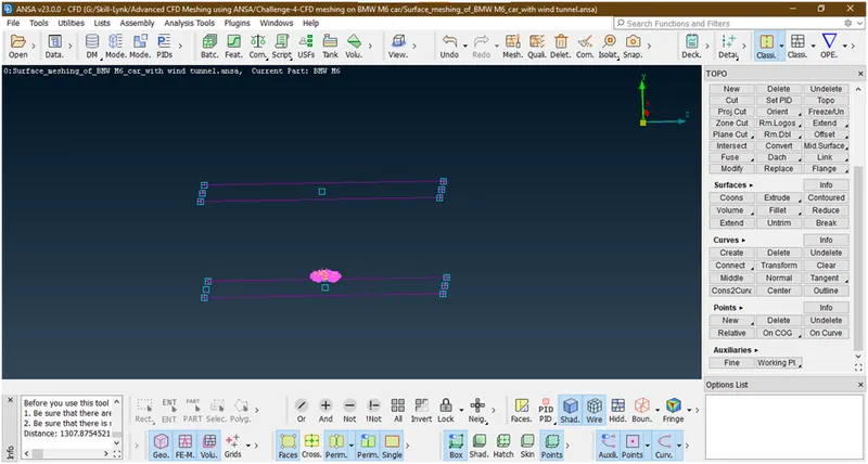
5. Now create a surface between these curves and set the pids.
- TOP SURFACE :
- Goto the faces->new-> select the curves
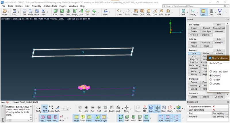
click middle key a new popup opens
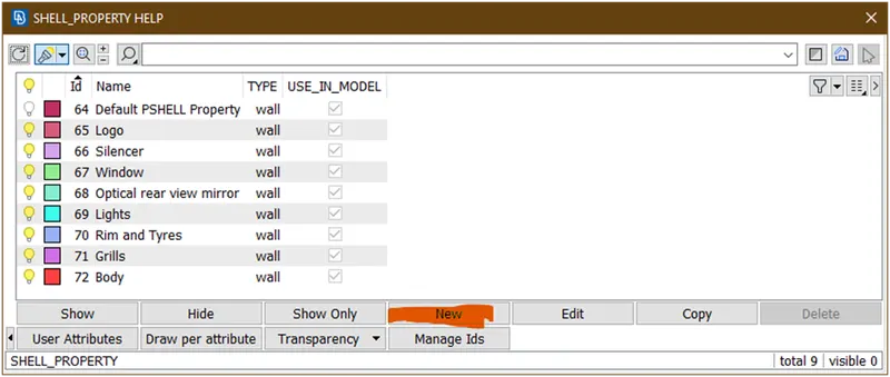
Click on new again new window open
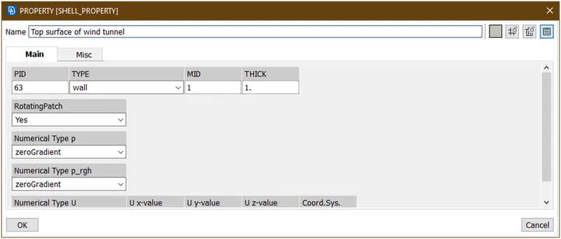
Give name as shown in figure and click on ok
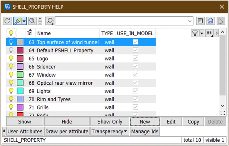
Double click on this
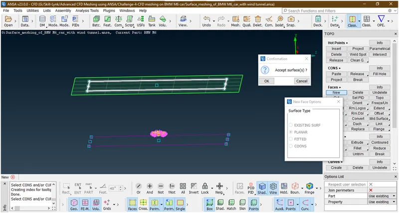
Click on ok
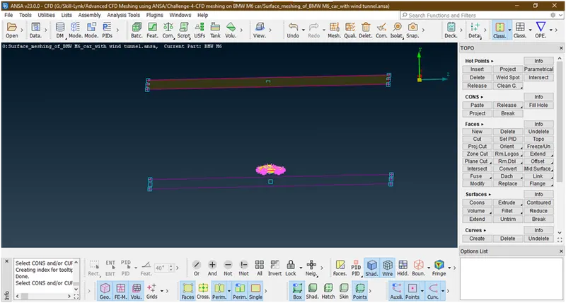
Similarly create all the faces.
- Bottom surface :
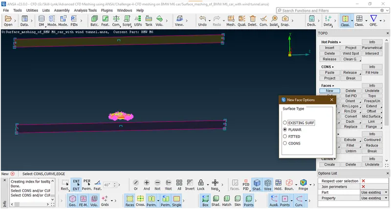
- Now we can delete these points and curves.for that goto pid manager and hide all parts
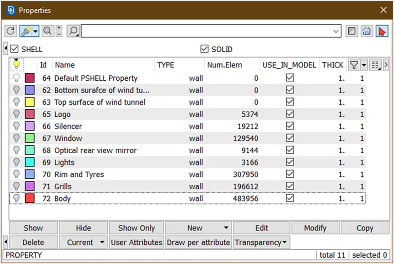
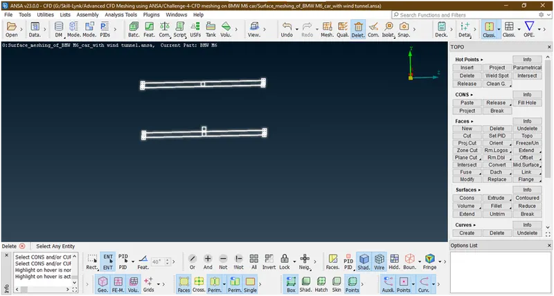
now delete all this and then click on all
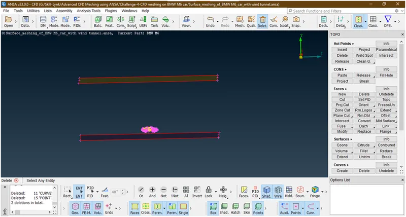
Now create the side faces
- All side faces :
- For crating the faces follow same procedure
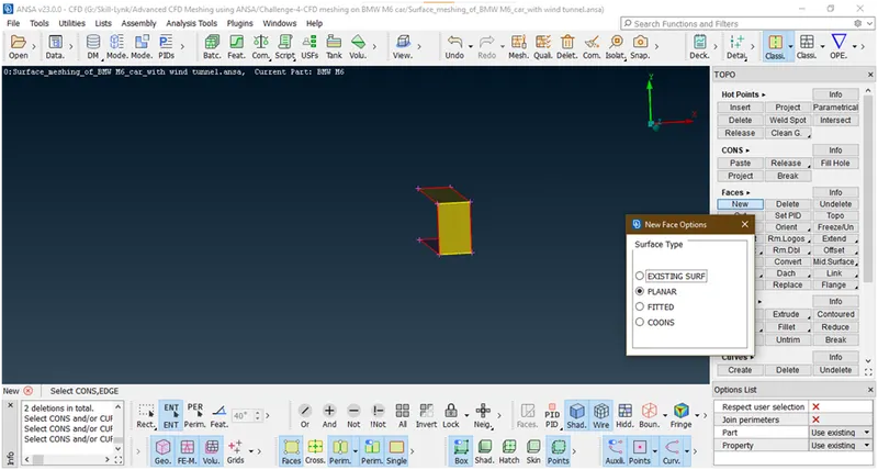
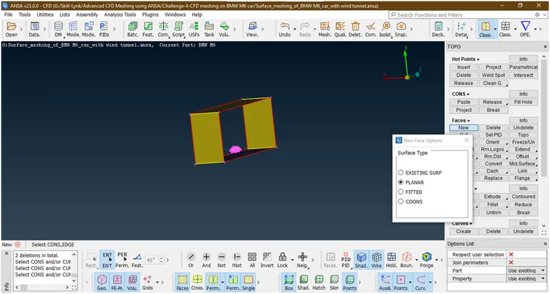
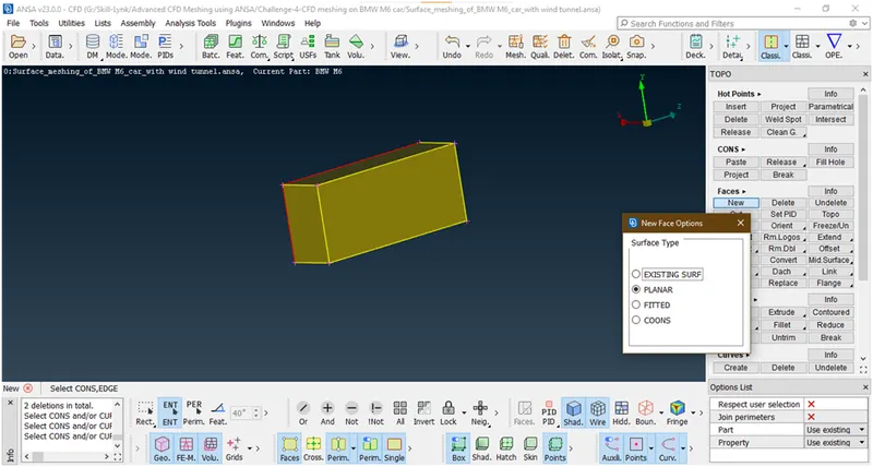
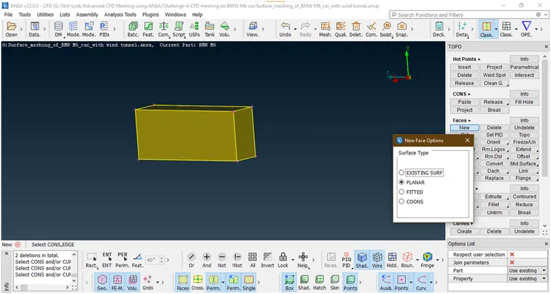
We have successfully created the surfaces.no we are going forward to mesh them.
2. Surface meshing of a wind tunnel :
- Goto classic mesh
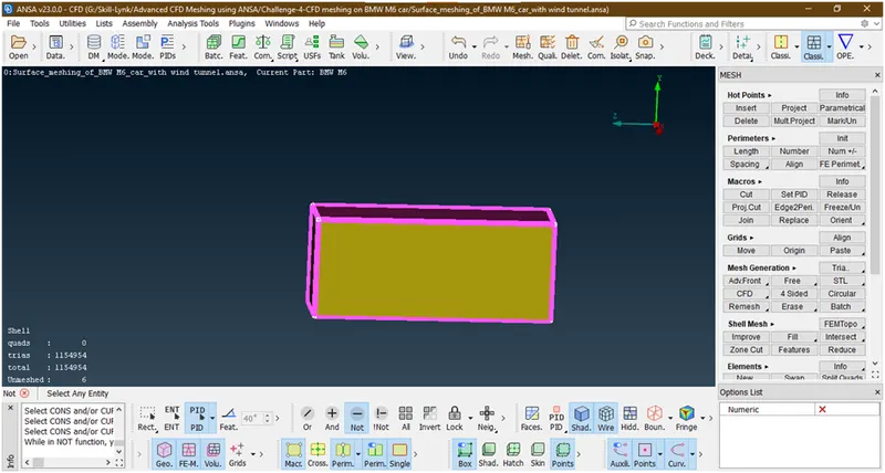 2. Goto pid manager and and hide car
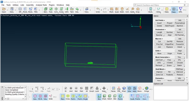
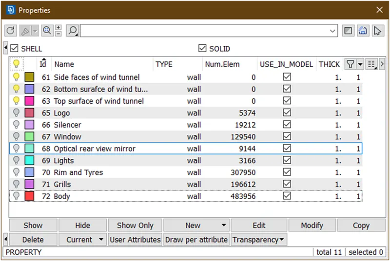
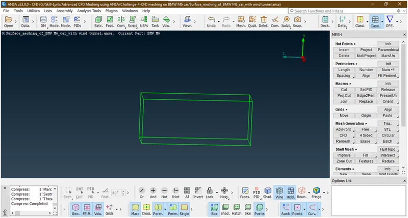
3. Let mesh bottom face with target length=50
- Hide other faces
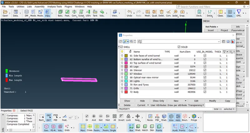
Goto mesh parameter and put min length=30,max length=70,hee we are giving the target length=50.
Then goto quality criteria and give max length=300
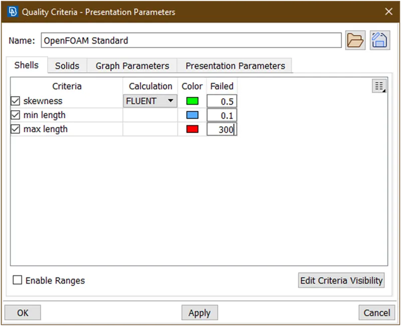
Click on apply and then click ok.
- Then goto perimeter-> length and give target value
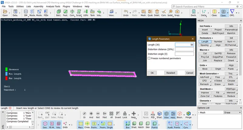
- Goto mesh generation-> spot mesh->visible
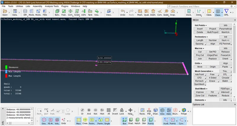
- Freeze the mesh
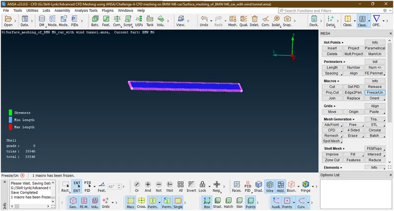
Now its done.
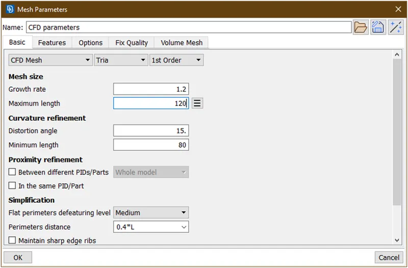
4. Lets mesh top face with target length=100.
- Goto pid manager and enable top surface
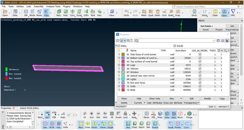
- Goto mesh parameter and give min length=80,max length=120
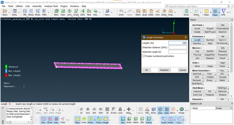
- Goto perimeter ->length-> select face-> give target length=100
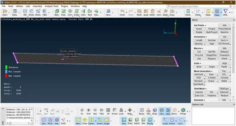
- Goto mesh generation->spot mesh->visible
- Freeze the mesh
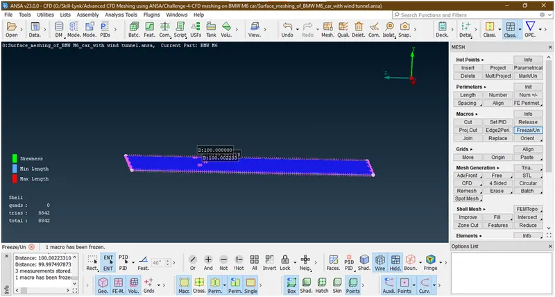
Now its done.
5. Lets go for side faces mesh.
- Goto pid manager->enable side face.
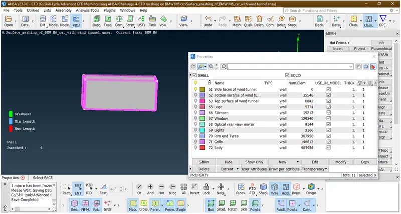
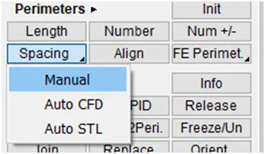
- Now here we are giving mesh as grain growth.so Goto perimeter->spacing->manual spacing
Then select the faces.
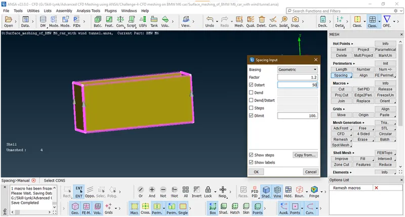
Chose faces in correct direction i.e. arrow start from bottom face and show towards top surface and gives dstart=50,dlimit=100 and click ok.
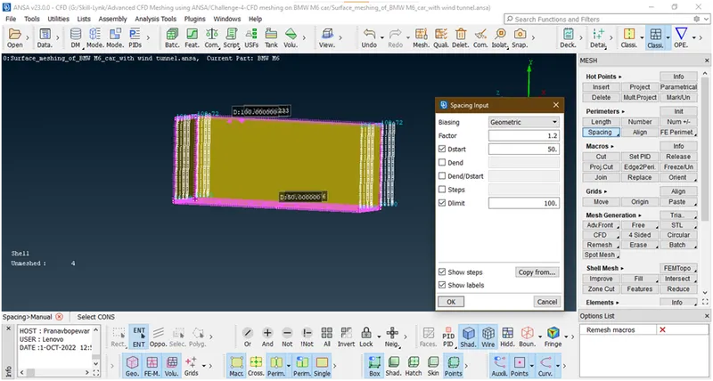
Its applied then press esc.
- Then goto mesh generation-> spot meshing-> visible
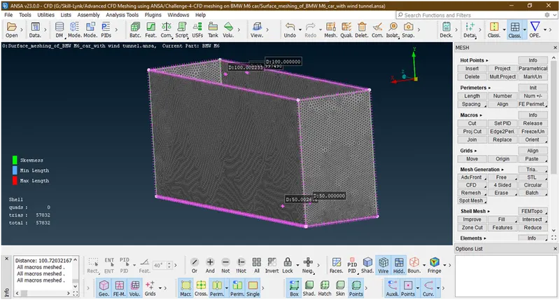
Now its done,
- Let freeze it.
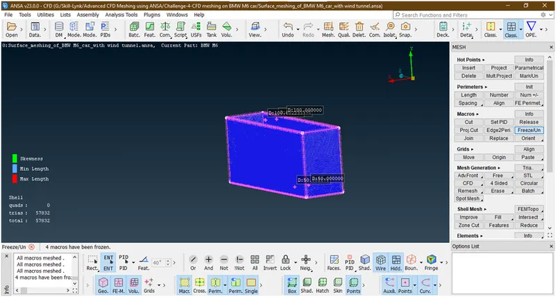
Now its done all meshing.
- Lets enable all part and see any elements ar off or not.
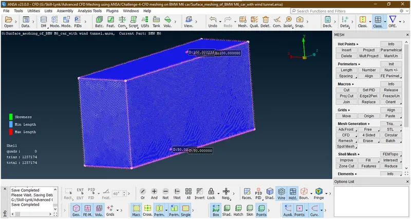
Now we can go for volume mesh.
- Before going forward please unfreeze the macros.goto macros-> freeze/unfreeze -> selcect the total body by right key of mouse only.
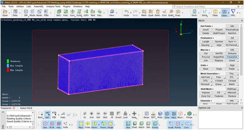
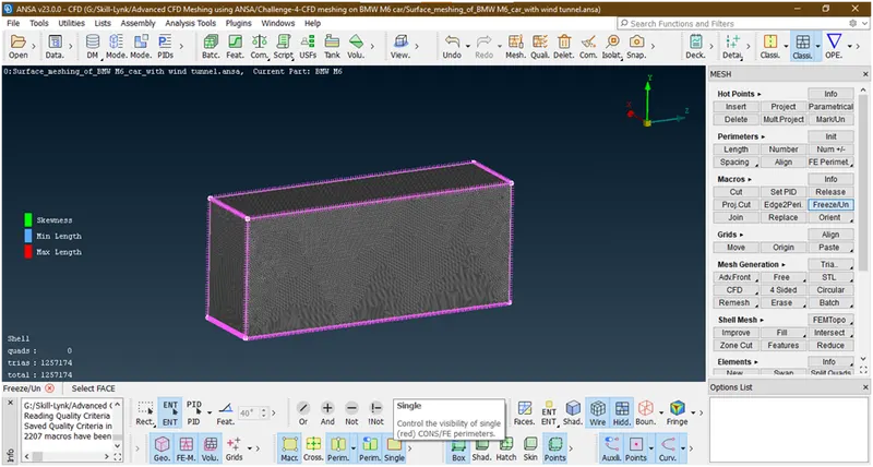
6. Volume meshing of a car with wind tunnel :
1. Lets go to volume mesh
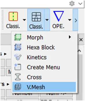
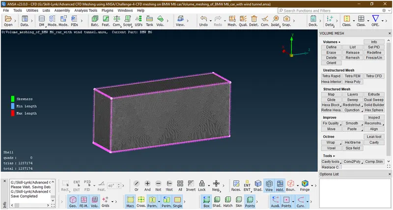
2. Goto volumes->defines then a new popup opens
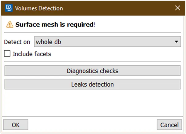
Click on ok then it shows volumes
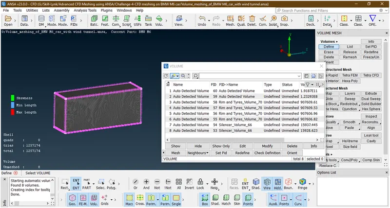
3. Let find out which are they and delete those volumes which do not required.
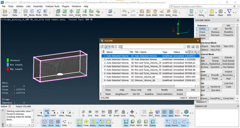
This is the volume considering wind tunnel and car so we nedd only this so we are keeping.lets go and check next volume
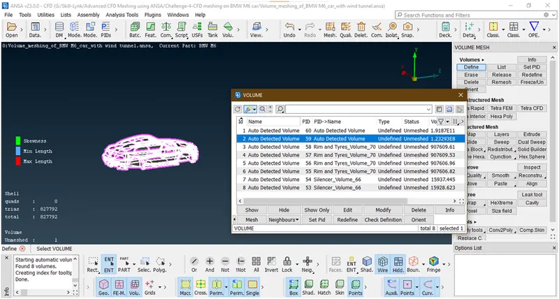
This is the car volume and don’t need as we have already considered so delete this.for just click on delete
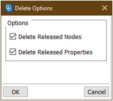
Click ok.then it deleted.
Lets check next volume
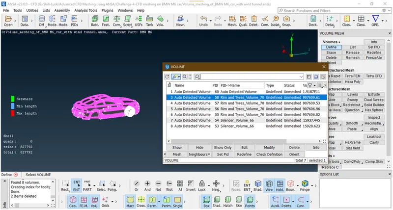
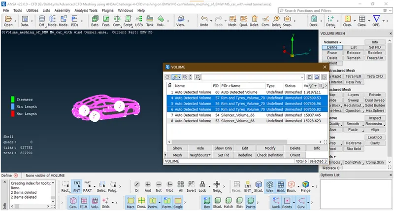
These are all tyres volume so don’t need so we are deleting.
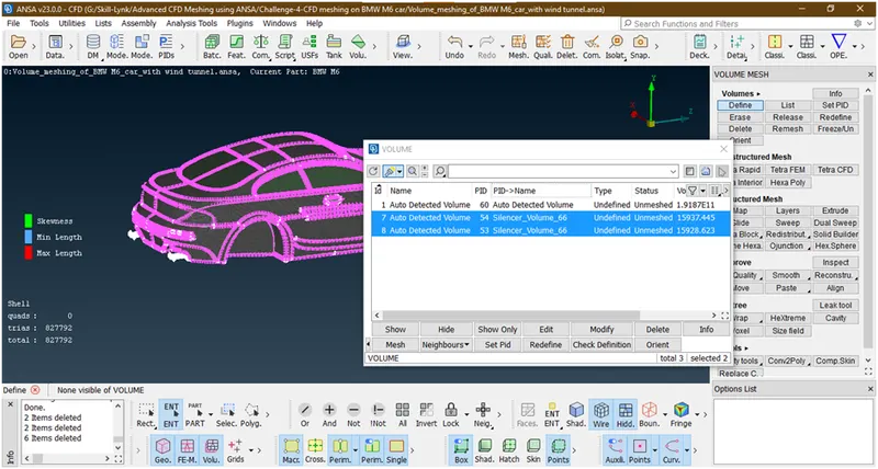
Now these also silencer volume so delete this.
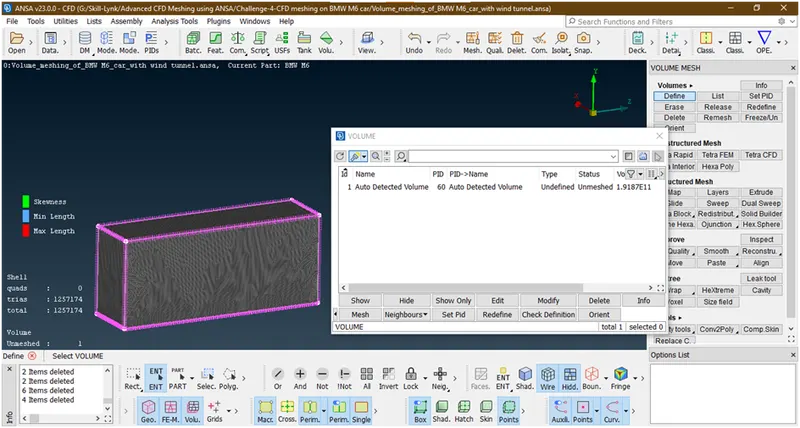
So we have left this only.
4. Lets go for meshing
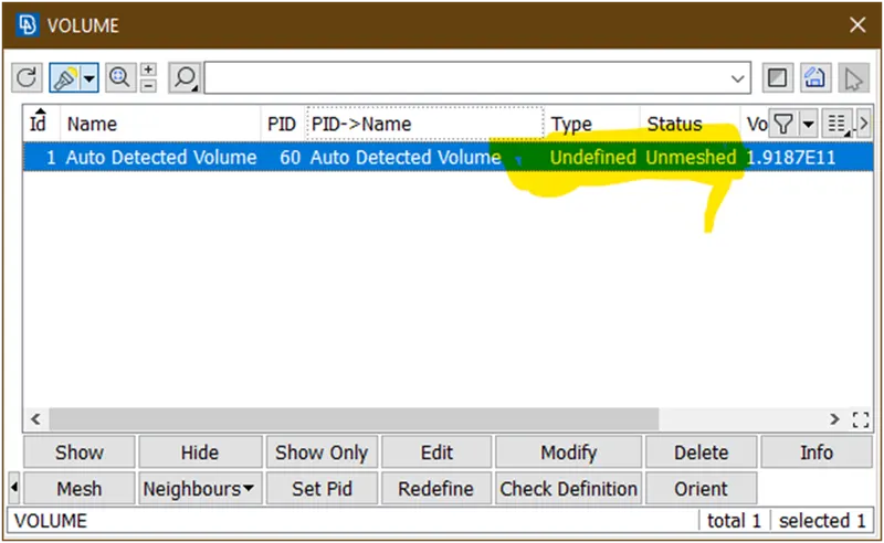
Double click on this undefined,a new popup opens
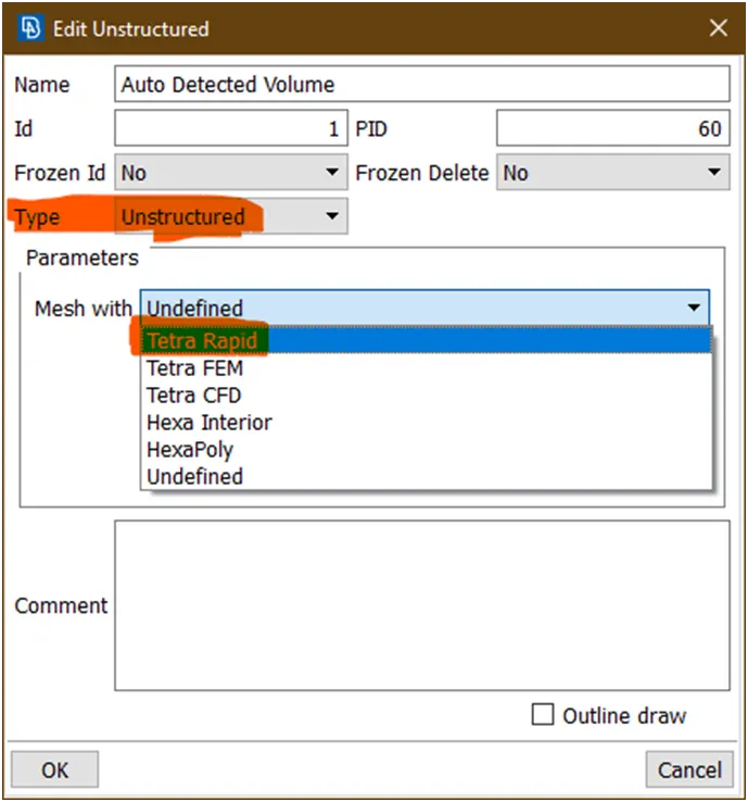
Select above highlited i.e. tetra rapid mesh type and unstructured.
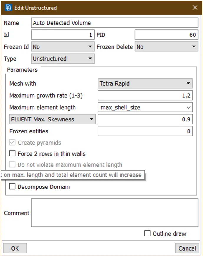
Then click on ok.
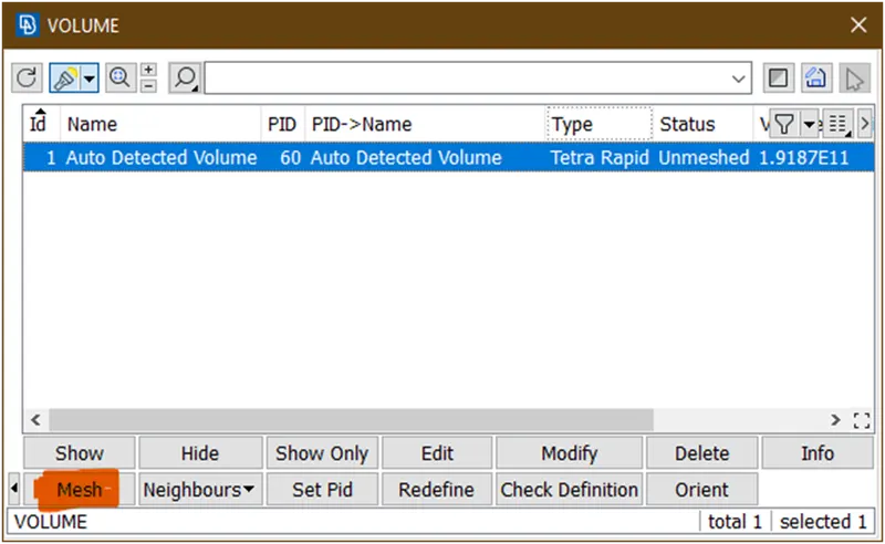
Then click on mesh and wait until mesh to be done.
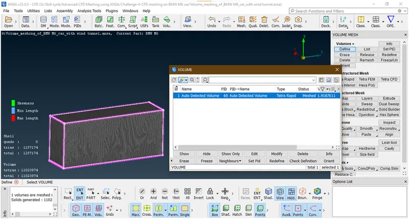
Now its done. now freeze it.
5. Now lets view in cut section view.for that goto cut plane->new->yz plane
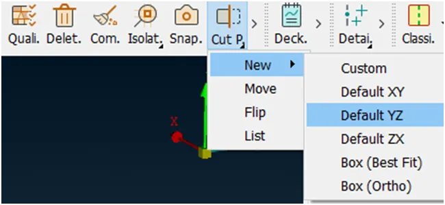
Now select any point,A new popup opens
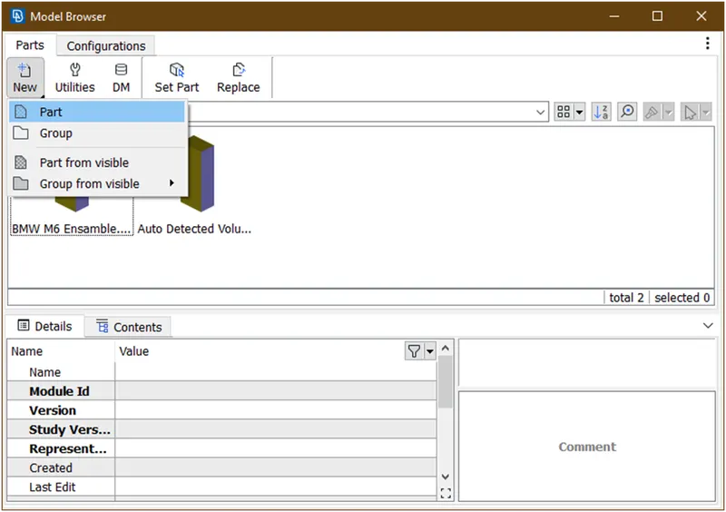
then go to new-> part
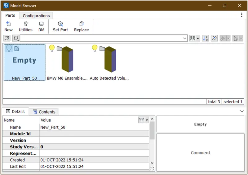
Then double click on this
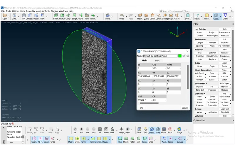
Then it will show as above then click on ok.it will create.
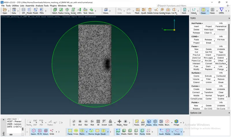
This is the final cut section view of volume and here we able to see volume.
Now its done all .so we are going to conclude all.
Results:
- Surface meshing of a car
- Surface meshing of a car with wind tunnel
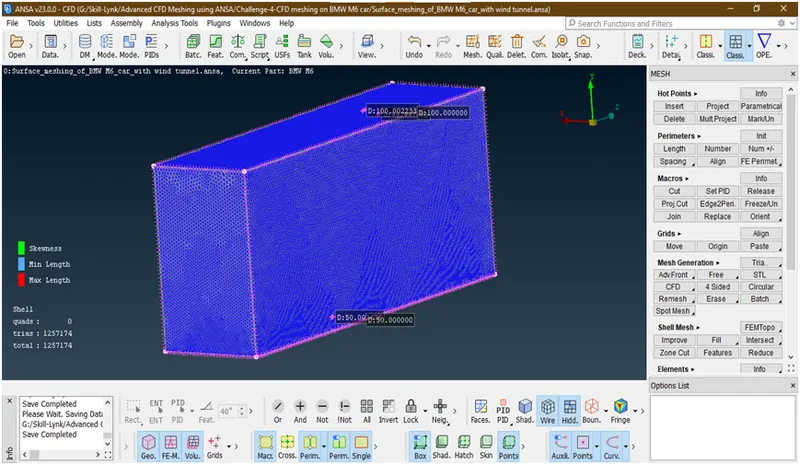
- Volume mesh of car with wind tunnel
Cut section view
Conclusions:
- I have learn how to make wind tunnel.
- I have learn how we can do volume mesh of car for external flow analysis.
Output files:
- Surface meshing of a car with wind tunnel
https://drive.google.com/file/d/1BPzc8EwDYOSFHK52aKqoIhQROLaP2Y4G/view?usp=sharing
- Volume mesh of car with wind tunnel
https://drive.google.com/file/d/1smIAufFg0dKxhkdnDY26QB8N2e68Odw9/view?usp=sharing