Week 3 Challenge : CFD meshing on Turbocharger
CHALLENGE-3
Aim : CFD meshing on Turbocharger
Objective :
- For the given model, check for the geometrical errors to make appropriate volumes. Create and assign PIDs as shown in the video. Perform surface mesh with the given target lengths as per PIDs.
- Blade stage-1 = 1 mm
- Blade stage-2 = 1 mm
- Impeller = 2 mm
- Shaft rotor = 1 mm
- Turbo casing = 5 mm
- Compressor casing = 5 mm
- Inlet casing cover = 5 mm
- Perform volumetric mesh for the required volumes as shown in the videos.
Theory :
- The turbocharger is a component which is used in the cars, trucks, 4-wheelers, 6-wheelers etc. to increase the running power of vehicle and also to increase the efficiency of a vehicle.
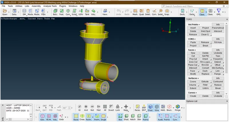
- It has a component like impeller, shaft rotor, turbo casing, compressor casing, and inlet casing cover as shown below figure.
- Working of a turbocharger :
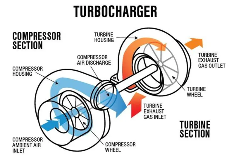
- Firstly the exhaust gas coming from engine goes into the impeller casing due to this the impeller starts rotating with a very high speed.
- This impeller is connected to the compressor blades through a rotor shaft. Now again these compressor blades starts to rotate. Due to which a negative gauge pressure i.e. suction pressure is created inside a compressor casing. Due to this the air starts suction in compressor and starts flowing.
- Now this compressor outlet is connected to engine inlet.
- So more air gets suction and flows to the engine. Due to which more combustion of a fuel takes place. It means the indicated power of a engine is increases because of this the efficiency of a engine increases and engine runs very smoothly.
Procedure:
1. Importing geometry:
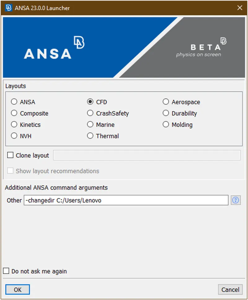
- Open the ansa software then the dialog box come as shown in below figure and For CFD applications it is recommended that ANSA is started in CFD mode, by selecting the corresponding option from the launcher window. This will allow the better setup of the software interface for CFD pre-processing.
 2. At ansa command argument write ‘-performance_mode 3’ for smooth running the software in regular laptops/pc because to run the this software we required high configuration but our pc’s are not build to run these software’s as shown in below figure
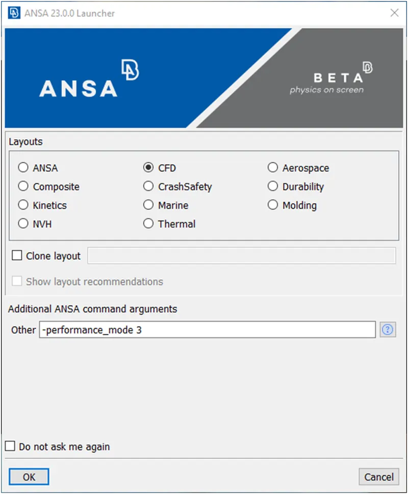
Then click on ok.
3. Now the ansa user interface is open as shown in below figure.
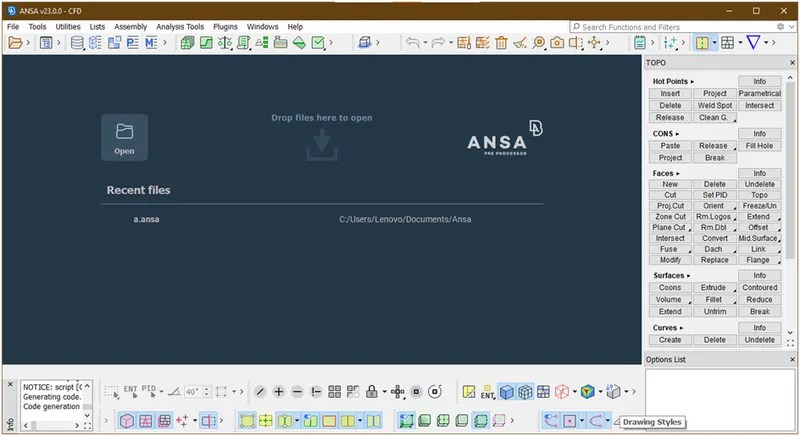 4. Now, right click on bottom menu then the dialog box is open as shown in below and finds show labels and click on radio button.
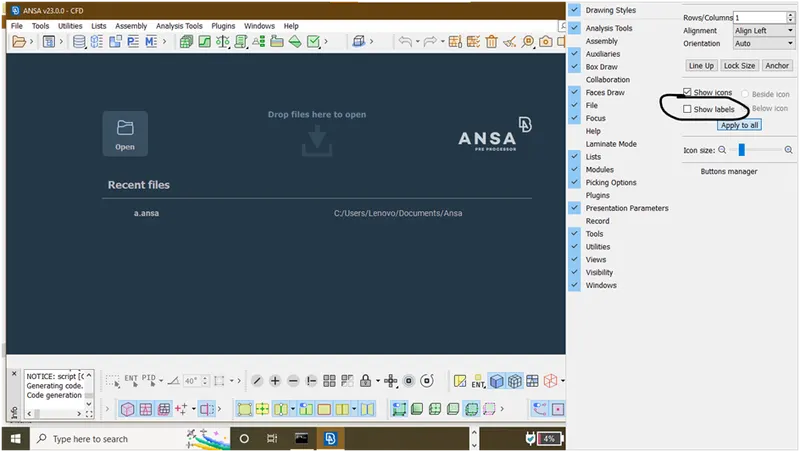
Now the labels will show as shown below figure.
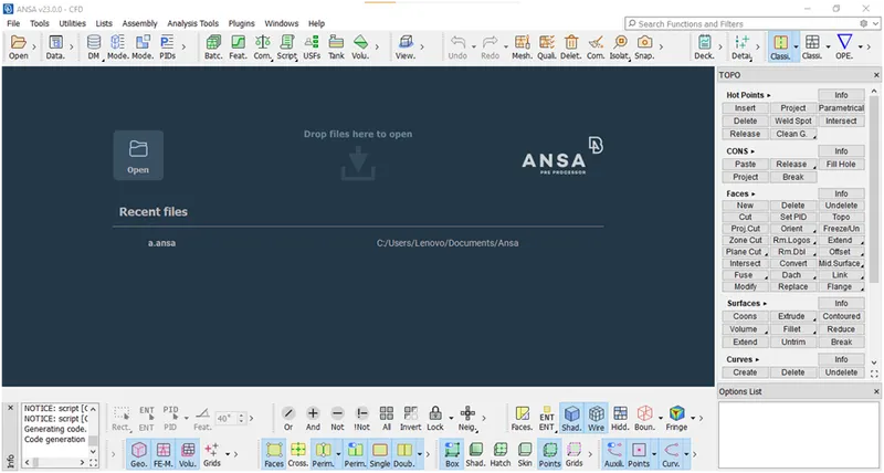 5. Open the ansa file which is required here.
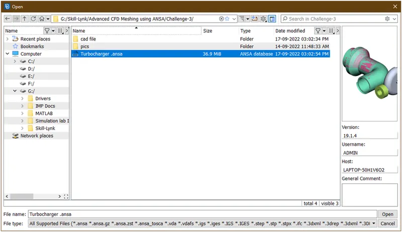
Here the geometry looks as shown in below figure.
2. Geometry Cleanup:
- Lets on the cross hatches on the geometry
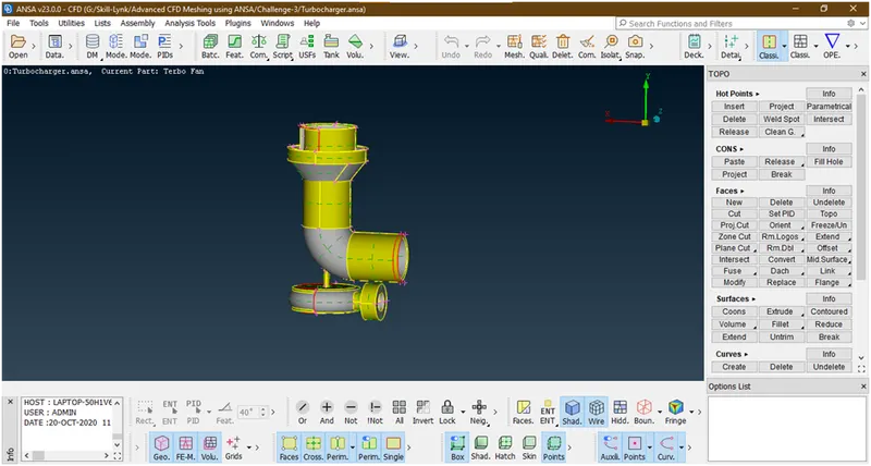
Now the geometry looks like
By looking geometry
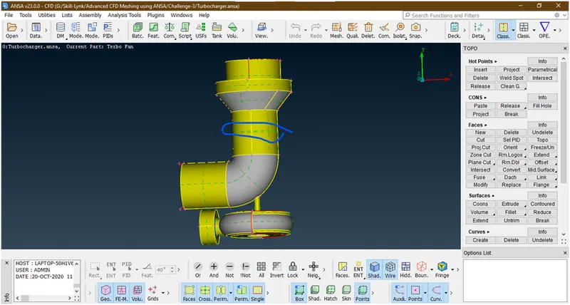
The some overlap surfaces to be seen means as shown in above figure at same point 2 cross hatches seen.
- Now this is in entity mode. So lets see geometry in PID mode
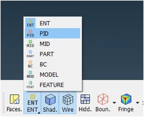
Now the geometry looks as
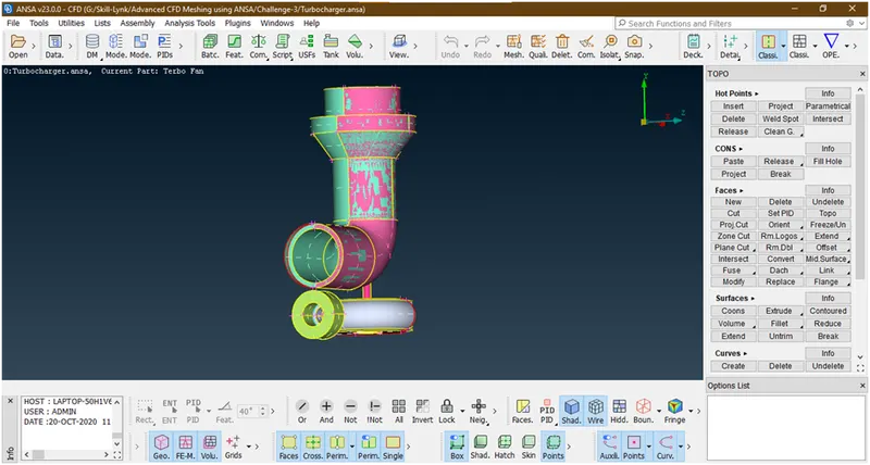
Now we are able to see some colour glitches seen on compressor casing.
- To autofix some error, lets hit topo to the whole geometry.
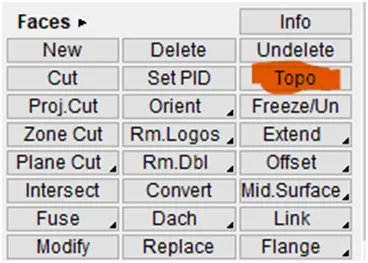
After selecting topo its ask for selecting cons
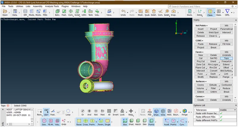
Select the cons by box selection
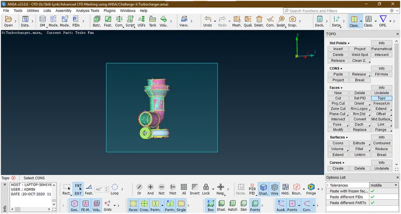
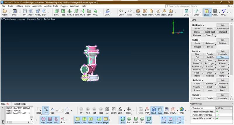
Now its selected. Hit the middle click of mouse
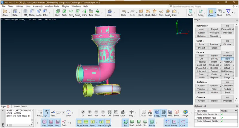
Now we are able to see triple cons on geometry. Now lets see why these triple cons are come.
Open pid manager
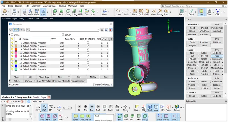
Lets focus on compressor casing by hiding all other components
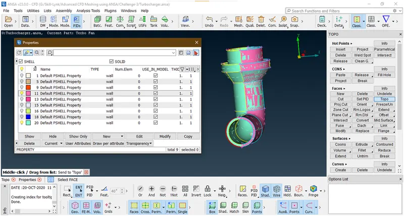
Lets firstly bulb off of pink shade
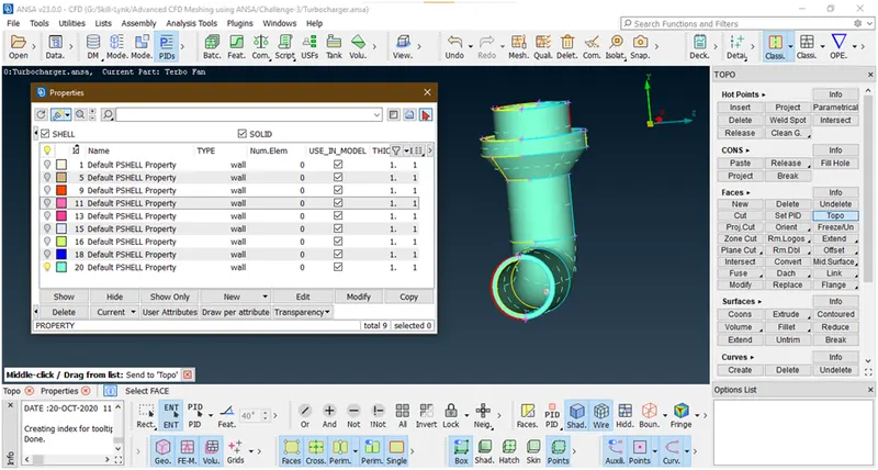
Now its look total body. so it is correct.
Now bulb on of pink part and bulb off of above part.
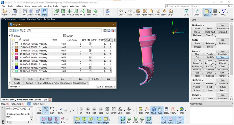
Now its look like a half portion of a body. So it not be needed so would go for delete this part by using universal delete tool
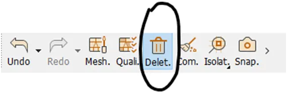
Now its asked for select the entity so we are selecting as follows
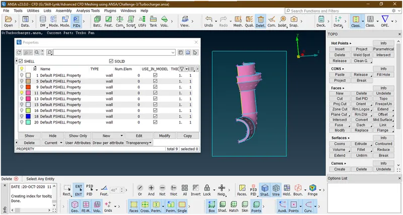
It has been selected
Hit the middle click to execute. After this a new popup opens as shown below.
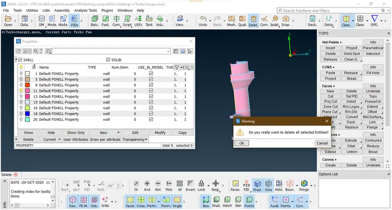
Click on ok.
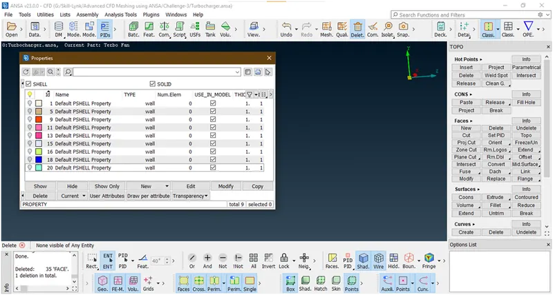
Now its gone.
Click on all to show all parts.
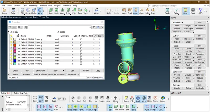
Now the all parts clear.
Now we are trying to delete the bulb off file by direct option but it can’t deleted. So we are using compressed tool.

A new popup opens
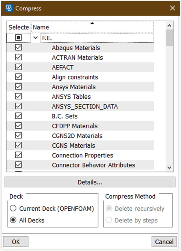
Click on ok.
The file is gone.
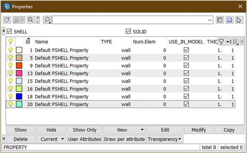
Now close this pid manager.
- Lets go for check tool to check geometry errors.
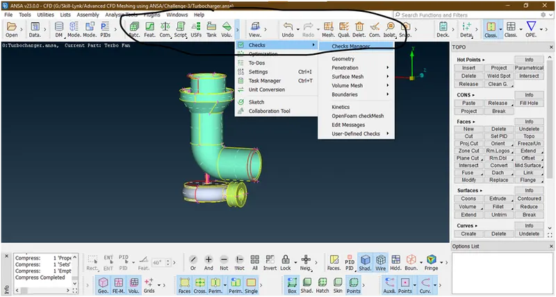
A new popup opens
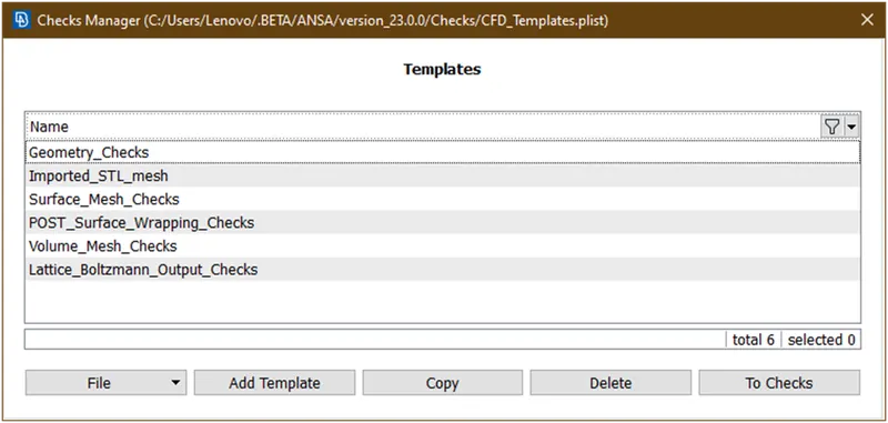
Double click on geometry checks. A new popup opens
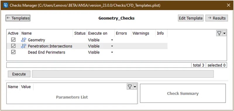
Click on execute.
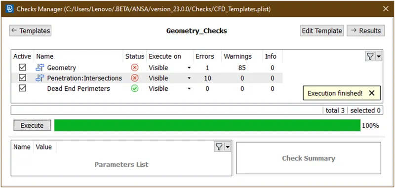
Lets see what are the geometry errors
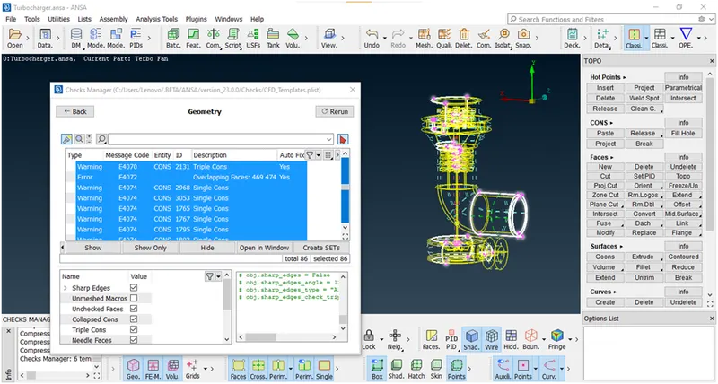
These are the geometry errors.
Lets see what are the interaction errors.
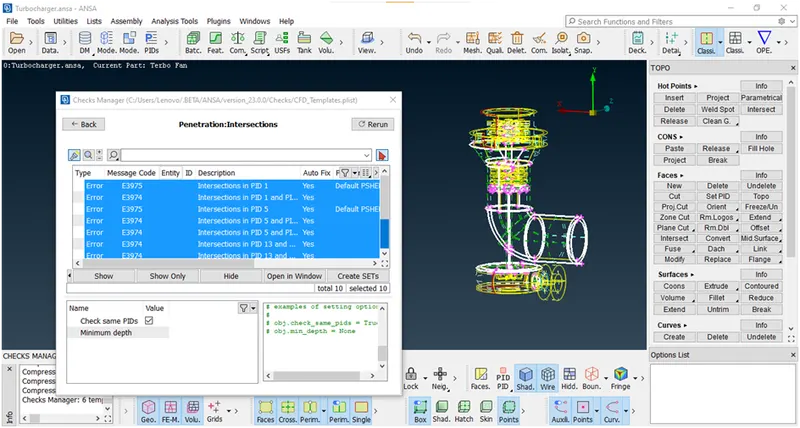
These are the interaction errors.Now close this dialog box.First clear the geometry errors.
- Lets clear this error
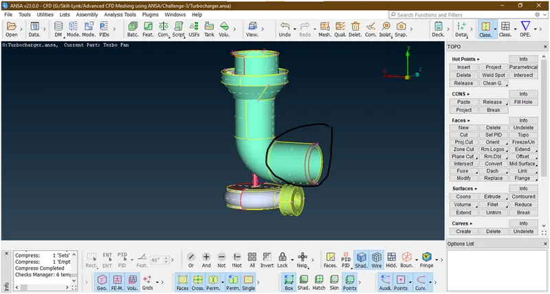
Lets hide all other parts by clicking on bulbs off in pid manager
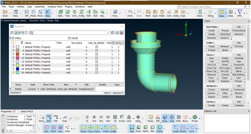
Close pid manager
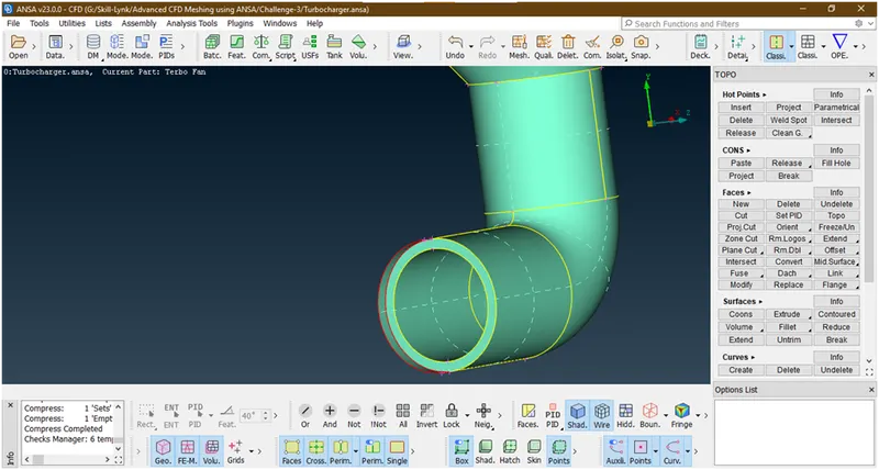
Now this is overlap surface.
So, we will go for delete this face by using delete tool under faces
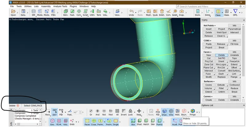
Now its asking for select the faces.
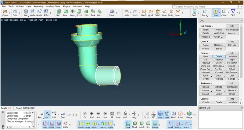
Lets select these faces
Now it has been selected, new popup opens
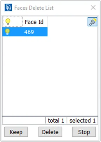
Click on delete
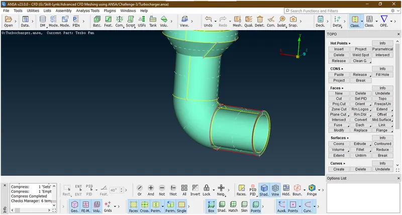
Some single cons are created.
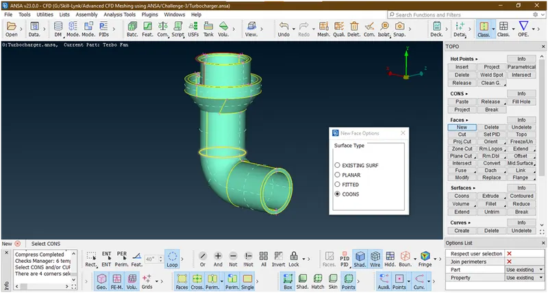
Now,create a new surface.
- Click on new-> click on coons-> select loop tool->select single cons from geometry where we want to create surface
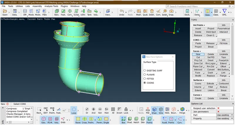
A preview will be shown
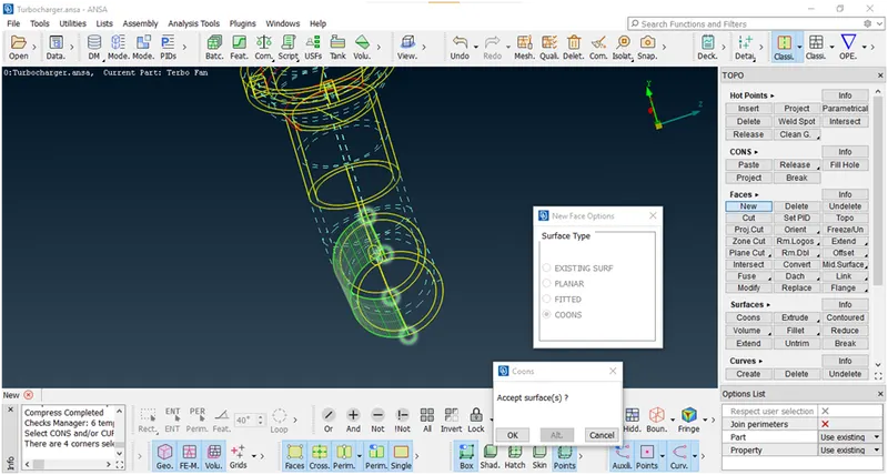
Click on accept ok
- The surface is created.
- Now click esc.
- Now we are going for next geometry error
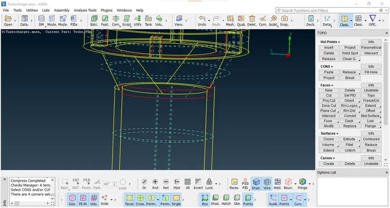
this is in the wireframe mode.
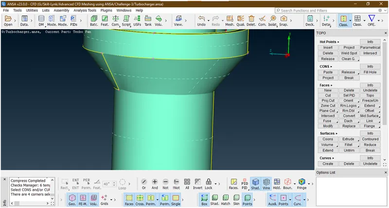
Here the con is not showing.
- So to create a con there, we are using intersect tool under faces.
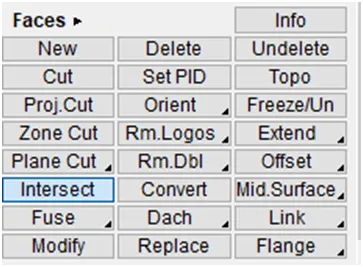
Now a new popup opens
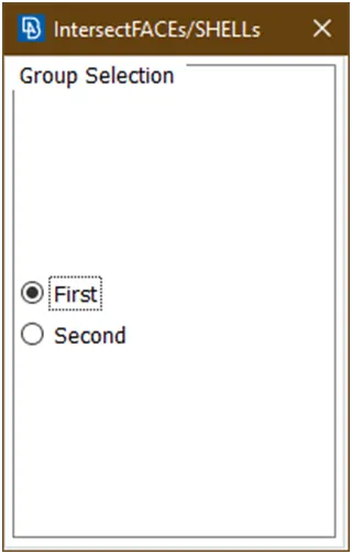
It means select the 1st entity
Now we are selecting as
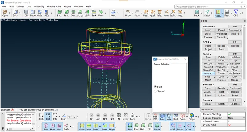
Click the middle click. then Now its asking for 2nd entity
Now we are selecting geometry
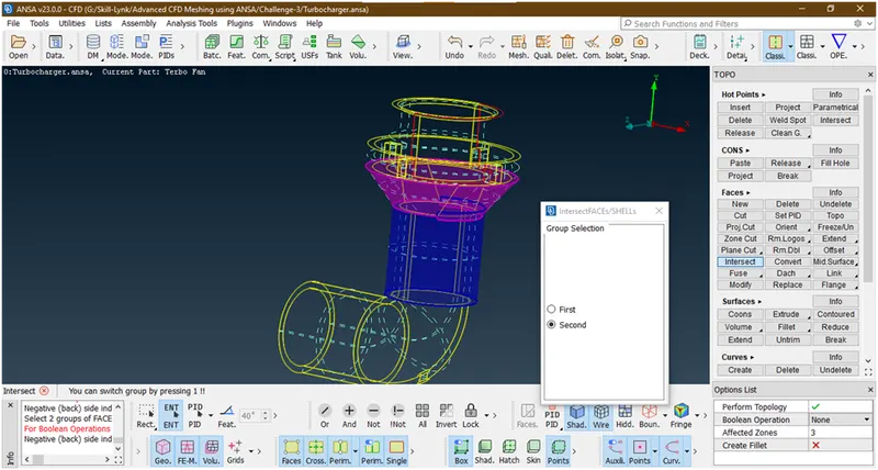
Hit the middle click.Then it asked for which surfaces do you want to keep and which surface delete
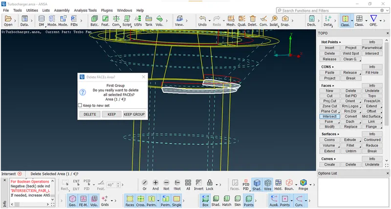
Asking for surface 1 which don’t want so click on delete
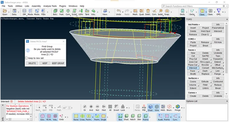
The 2nd surface we want so click on keep
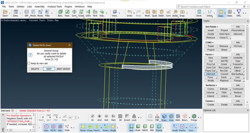
This 3rd face we don’t want so delete this
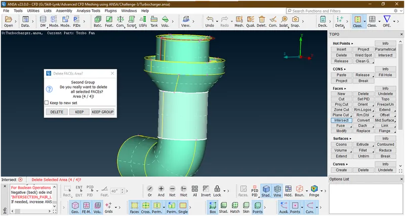
This 4th face we want so click on keep.
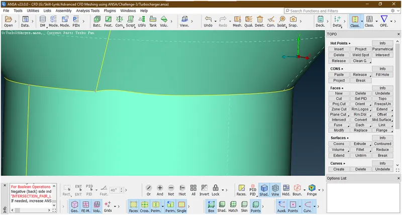
Now con is created but there is a distorted coon so we using cut tool to make uniform coon
Select first hotpoint
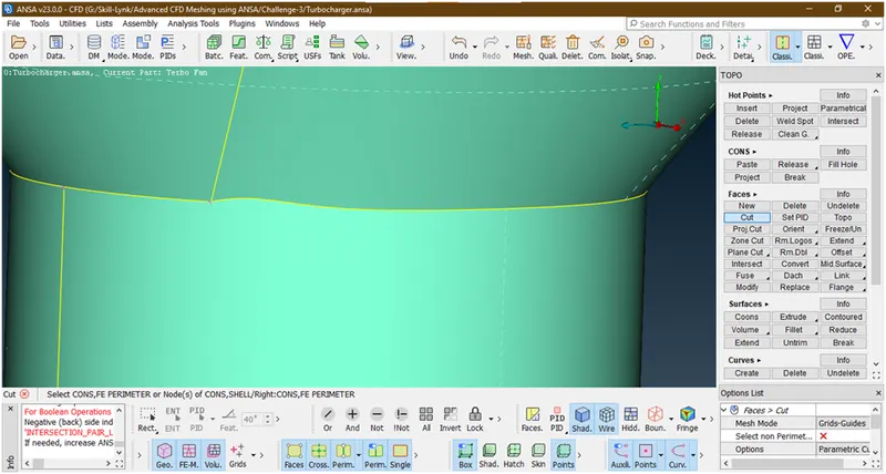
Select the coon/hotpoint
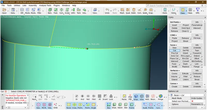
Now it has been selected.
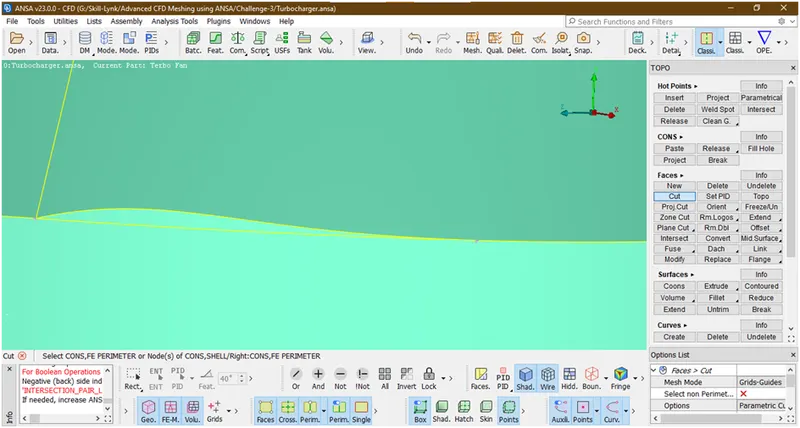
Now we are deleting this face
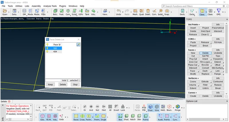
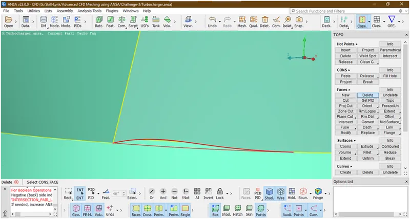
Similarly we are doing on other side also.
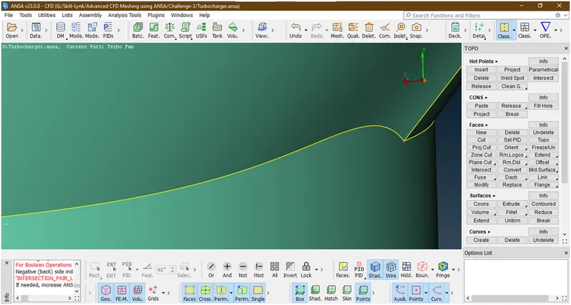
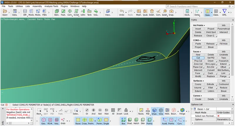
Use cut tool
Now we are deleting this surface
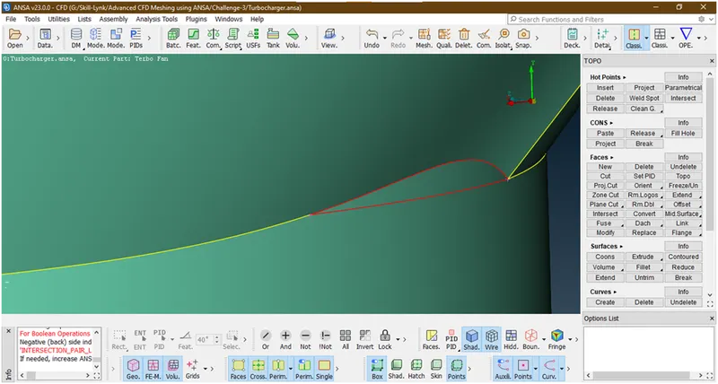
Now we are deleting this surface
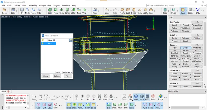
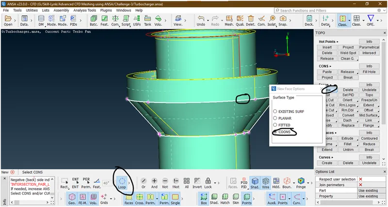
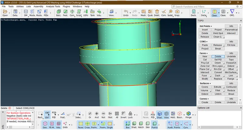 Again we re-creating a new face there by using new (faces)->coons->loop
Preview is
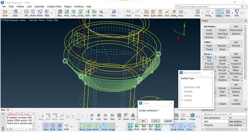
Click middle click.
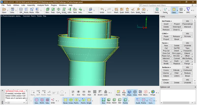
- Now we are going for next error
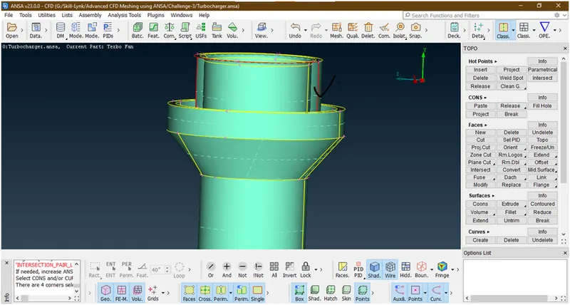
- To see clear first of all hide some faces by using not and entity

Now we are able to see these single cons.
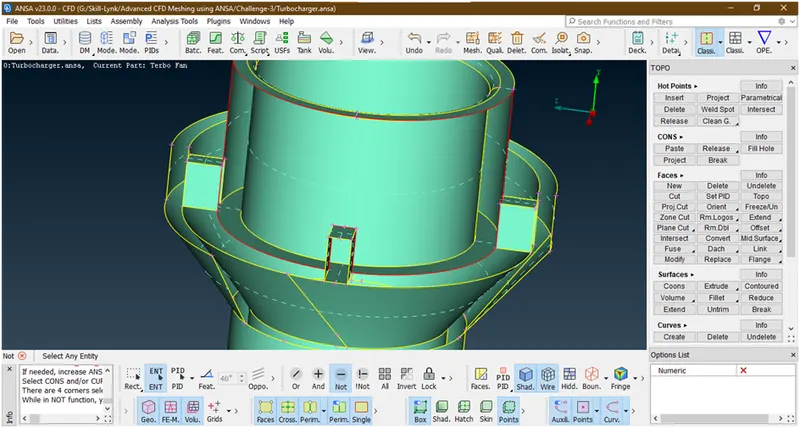
This is a complex cons so to create faces following steps are use
- Select transform tool under curves
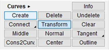
Its asking for select the entity
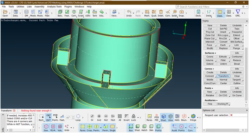
Now select cons which we want to transform/project
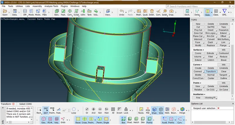
Hit middle click
Now its showing arrow how curve draws and askink for node/entity
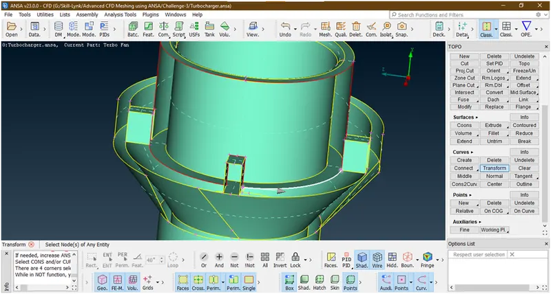
So select the hot point near to base of arrow
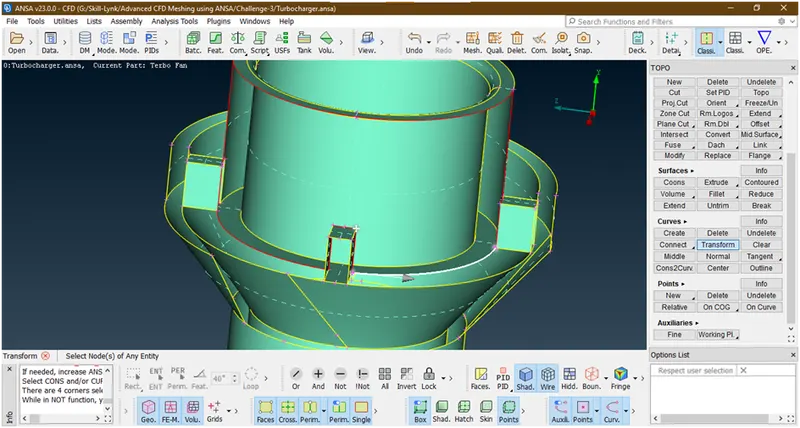
Now select the 2nd point,the curve is automatically create
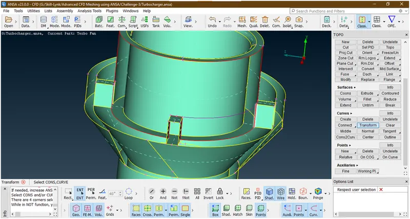 Now create a surface there
New(under faces)->coons-> entity selection as shown below
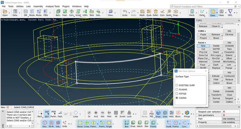
Preview is
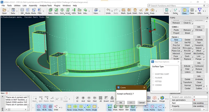
Click on ok.
The surface is created.
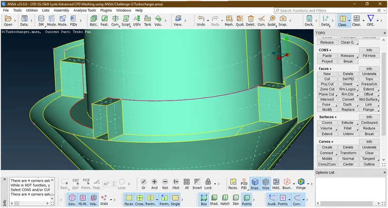
- Repeat this procedure for other side also
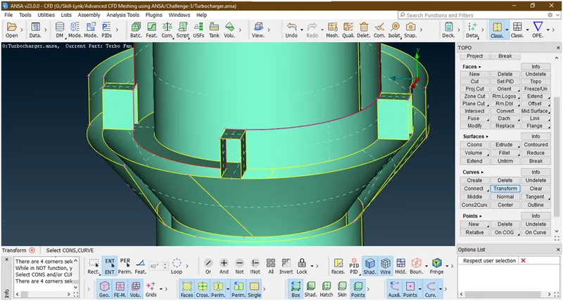
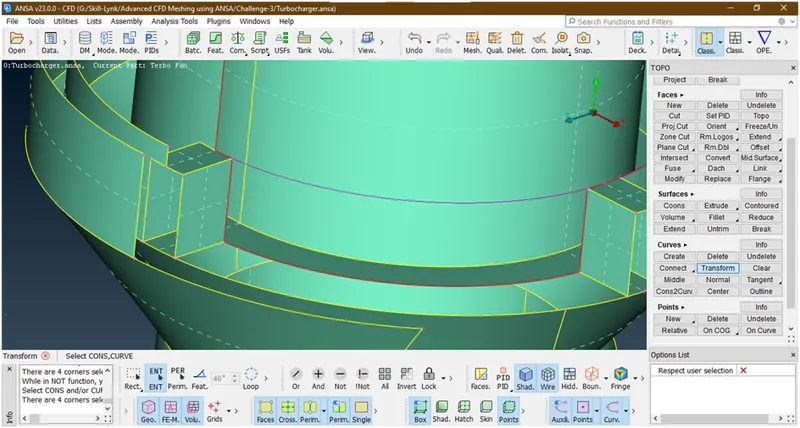
now create the surfce here
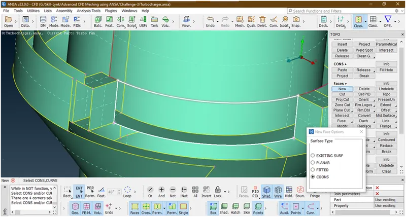
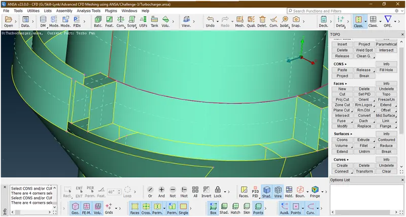
- Now deleting these curves
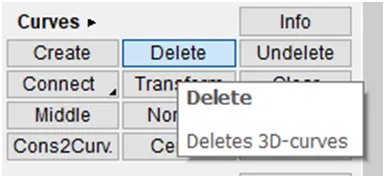
Selecting curves
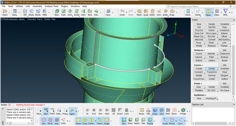
Hit middle click.
A new popup opens
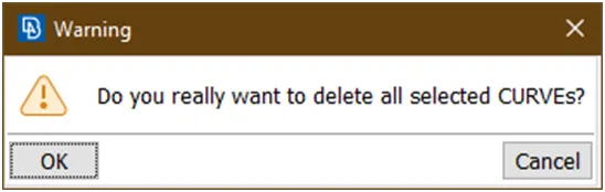
Click on ok.
Now it has been deleted.
- Now the remaining face is created As shown below
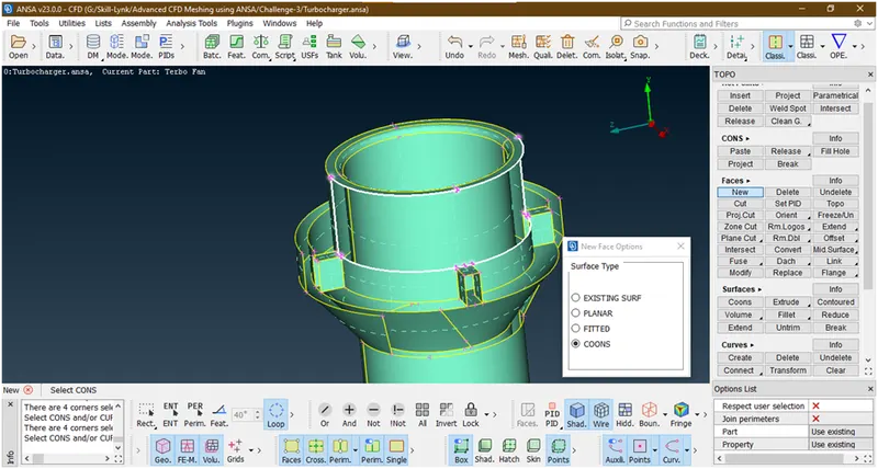
Now its created.
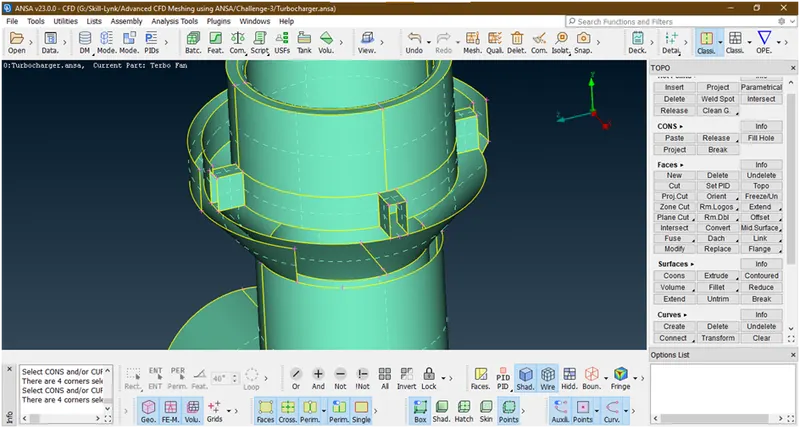
Click on all to go further
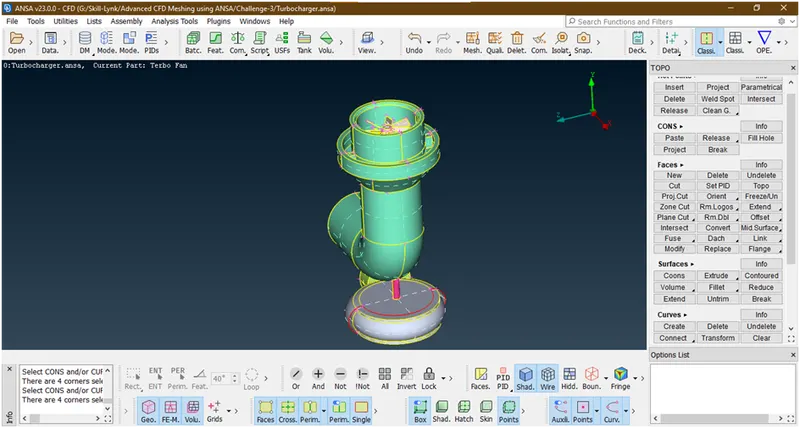
- Now we are going to clear a single coon in impeller casing.
- Lets hide all other part except impeller casing by using open pid manager now click on bulbs infront of other parts as shown below to off.
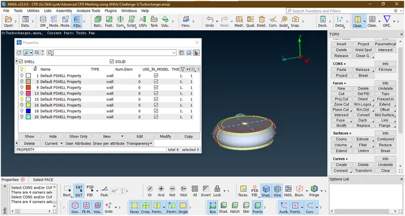
Close this pid manager box
- Insert a hot point
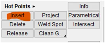
Select con where we want to insert hotpoint
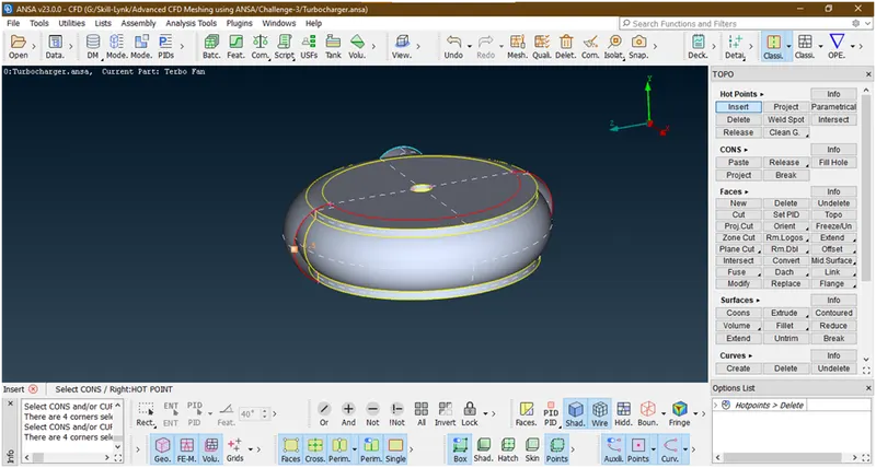
Now it has been inserted.
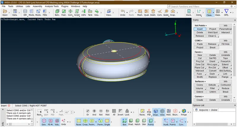
- Goto the transform tool
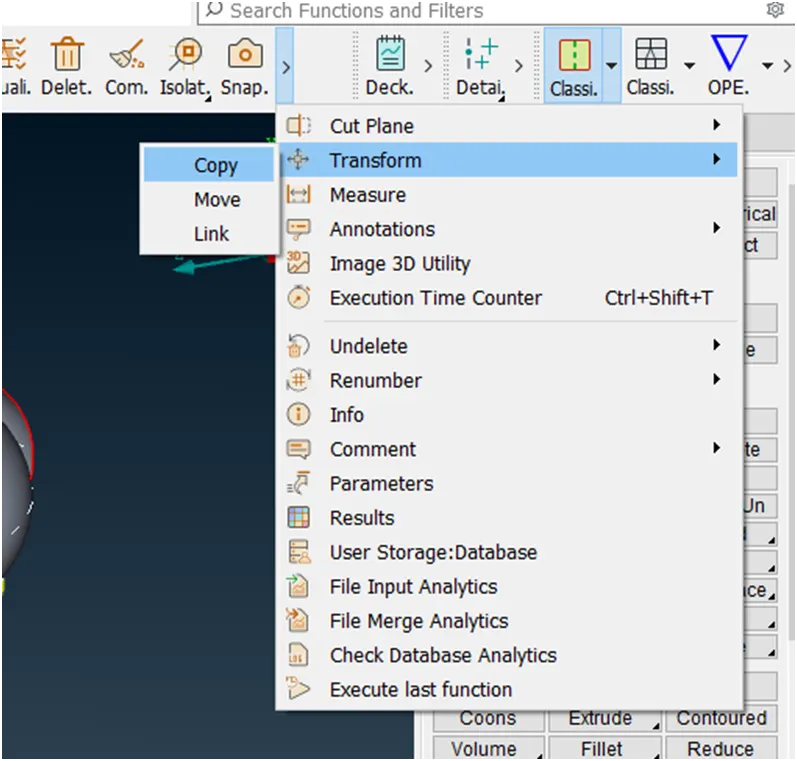
Click on copy, A new popup open as shown
Select entity which we want to copy
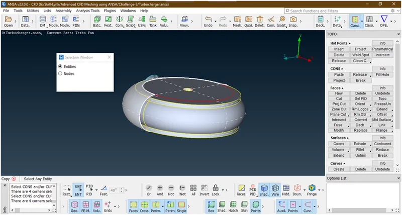
Click on middle click ,a new popup opens
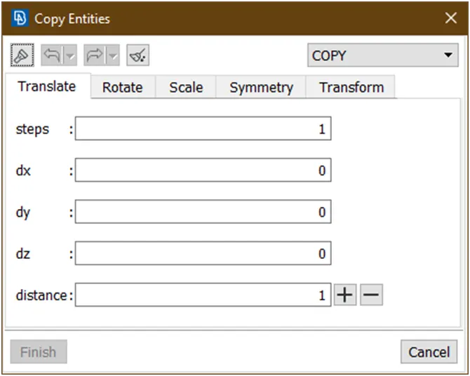
Goto symmetry, Select mirror 3 points plane
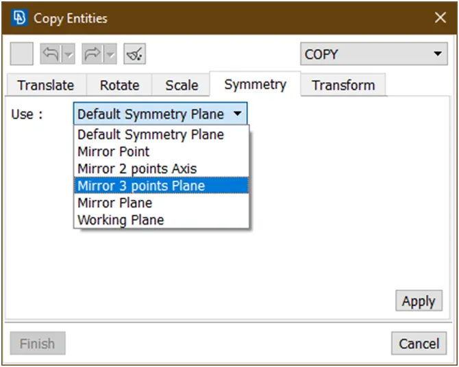
a new popup opens
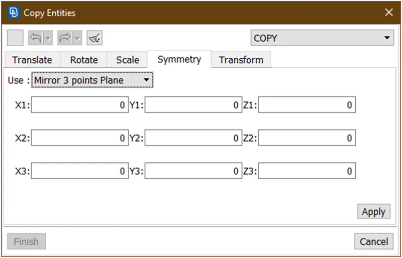
Now select the 3 points from geometry
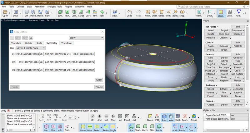
Click on apply, again new popup opens
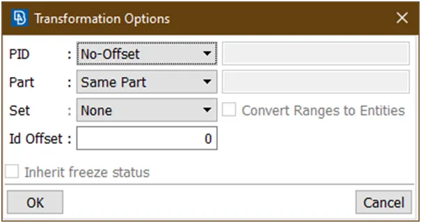
Click on ok
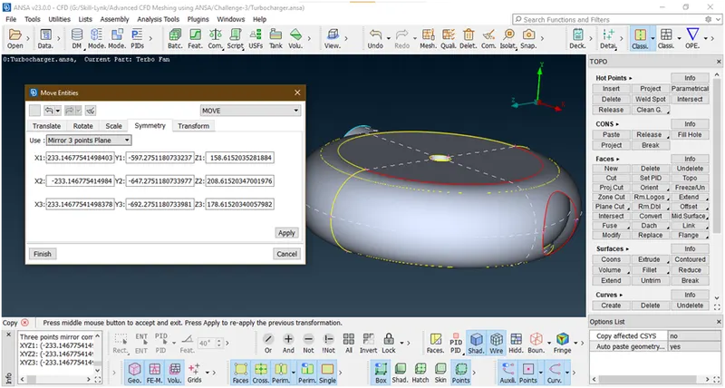
Now geometry created as shown in figure,
Click on finish.
Click on esc from keyboard .
- Now we we are filling the hole by using ‘FILL HOLE’ tool under cones.
Select the cons
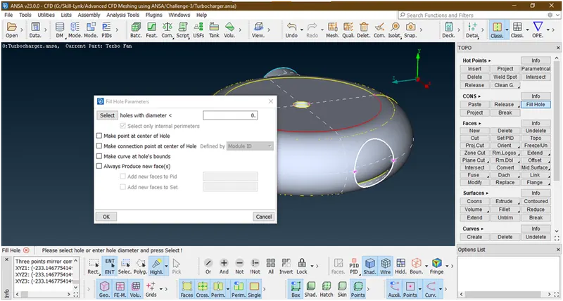
Click on ok
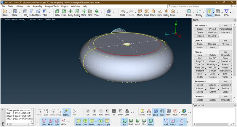
Now its done.Now this red single con appears lets see why this come.its nothing but due to not proper connection established.
Lets apply topo here to fix this error.
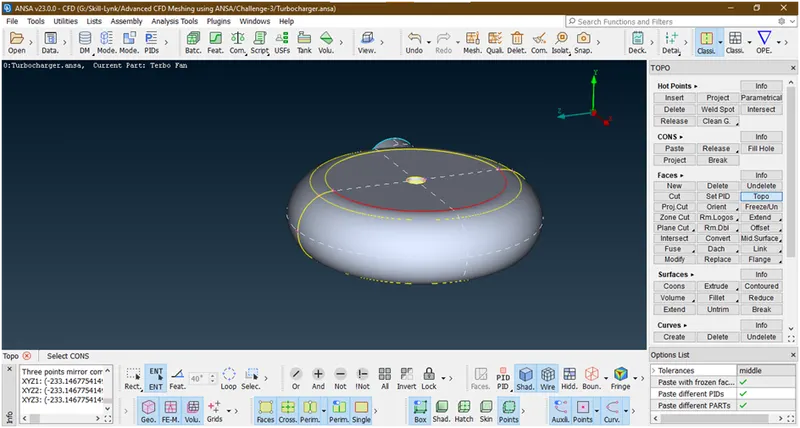
Selecting total impeller casing by box selection
Hit middle click
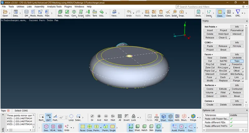
Now its done.
- Now click on all to show all parts.
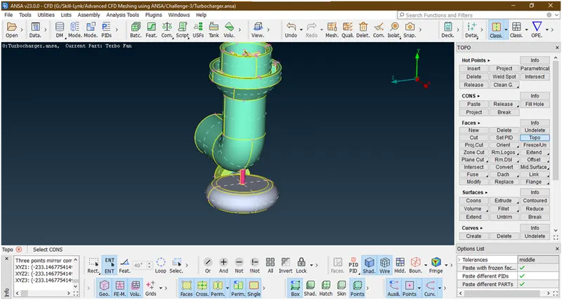
- Now, lets again check for any errors.
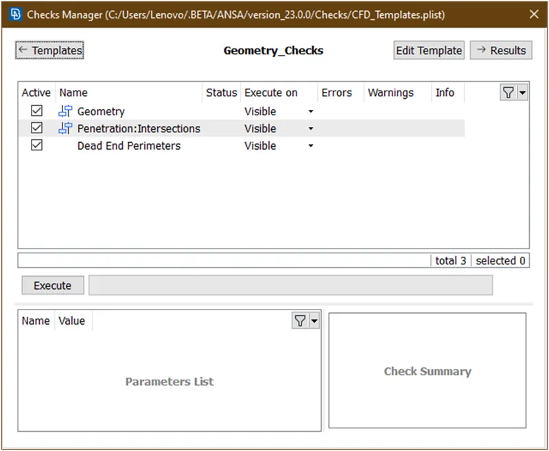
Click on execute
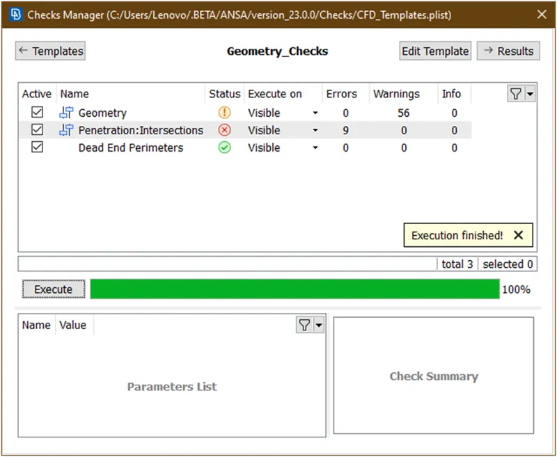
- Lets geometry by double click on this
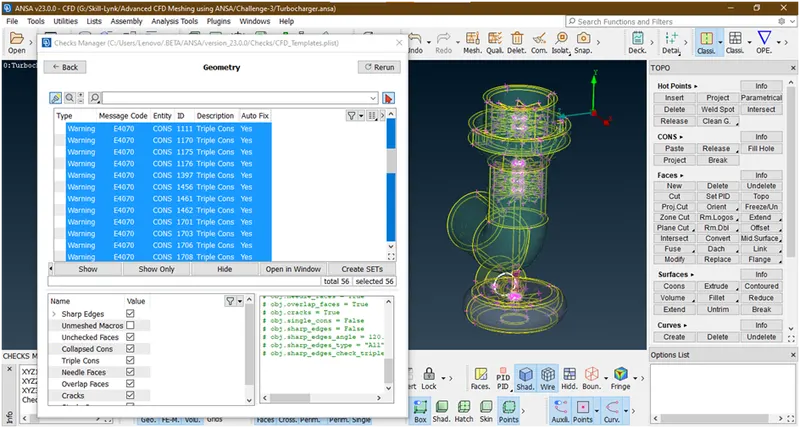
Now these are all triple cons
- Now lets see where the interaction errors occurred
these are the interaction errors occurred.
Lets try to remove these errors.
- Lets hide compressor casing,impeller casing,inlet casing,impeller and lets focus on rotor shaft and blades stages.
- Goto pid manager
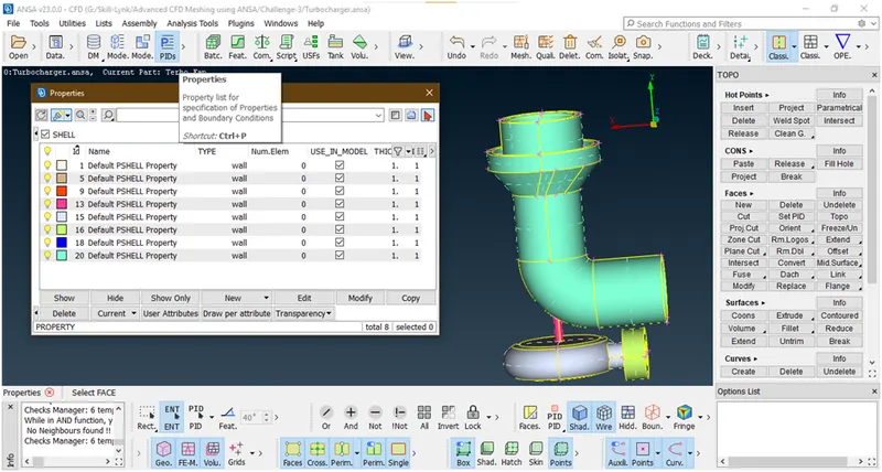
Turn off bulbs which we don’t want to see.Now close this dialog box.And lock the geometry.
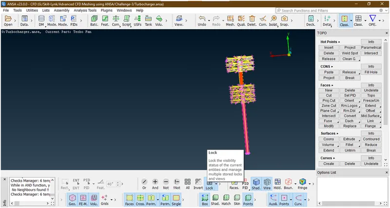
- Now we are seeing some triple cons
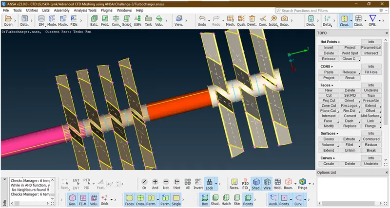
Lets apply not
Selecting faces
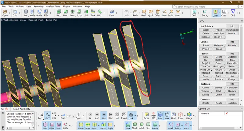
- Now try to delete this face
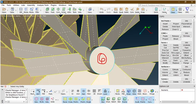
Now selecting faces and click on middle click.
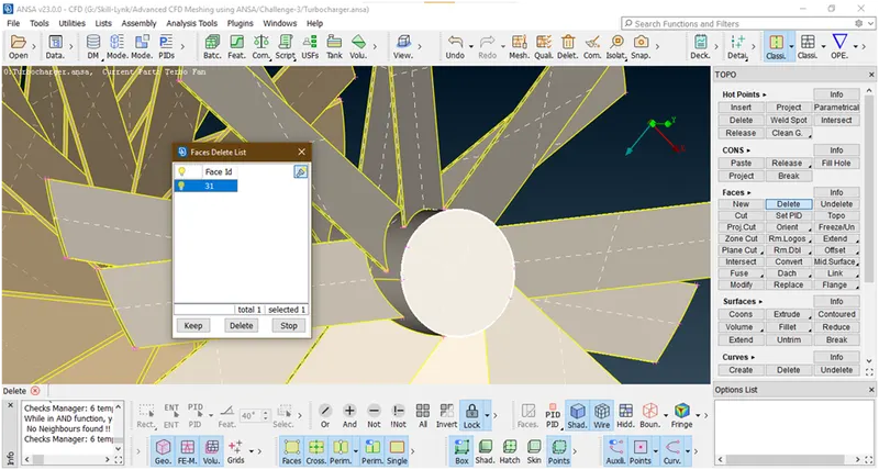
There are 2 surfaces so we don’t want so delete this.
Finally it looks like
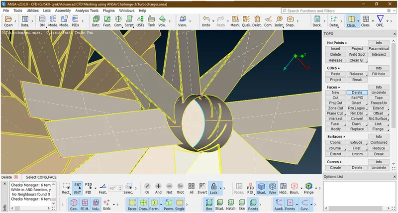
- Going for next part
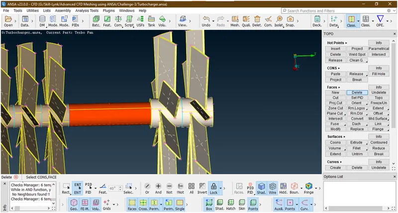
Repeat the same procedure
Now delete this faces
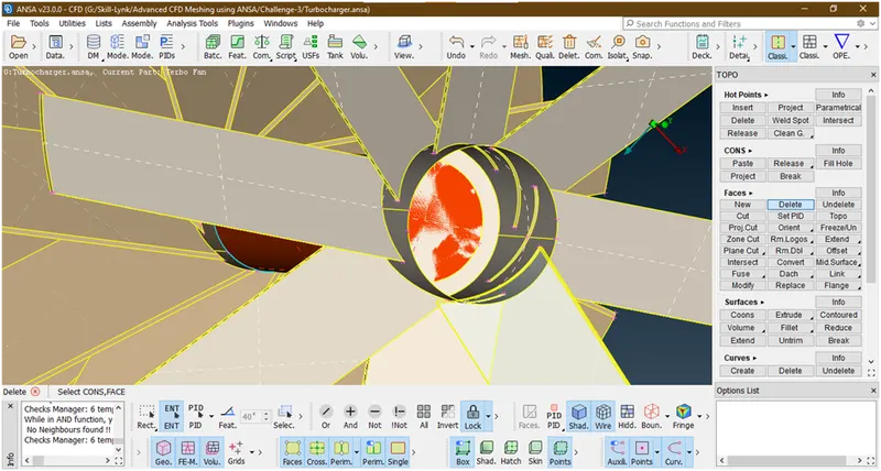
- Now going for next surface
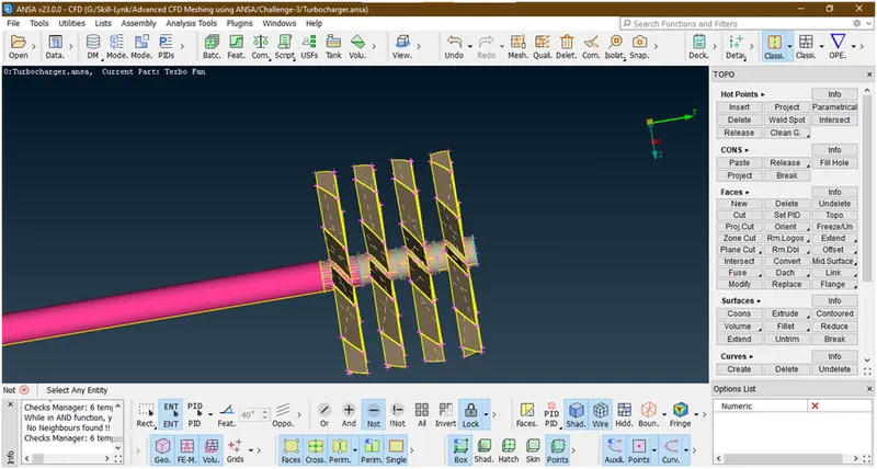
Now repeat the same procedure and delete the circular plates which are shown like above.
- Going for next part
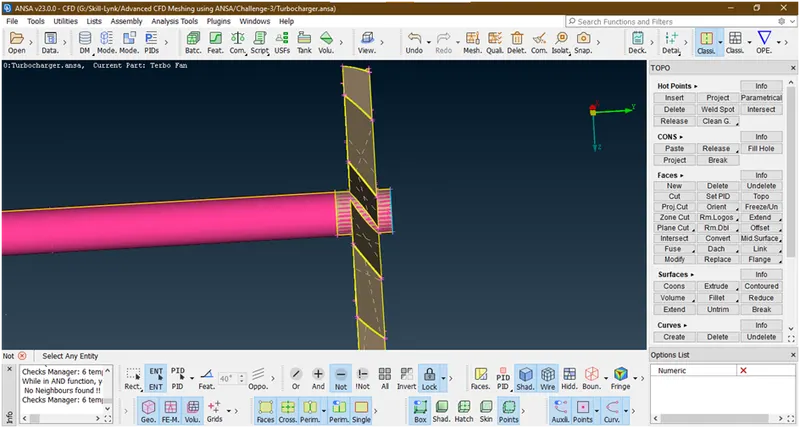
In this area there is a overlap surface
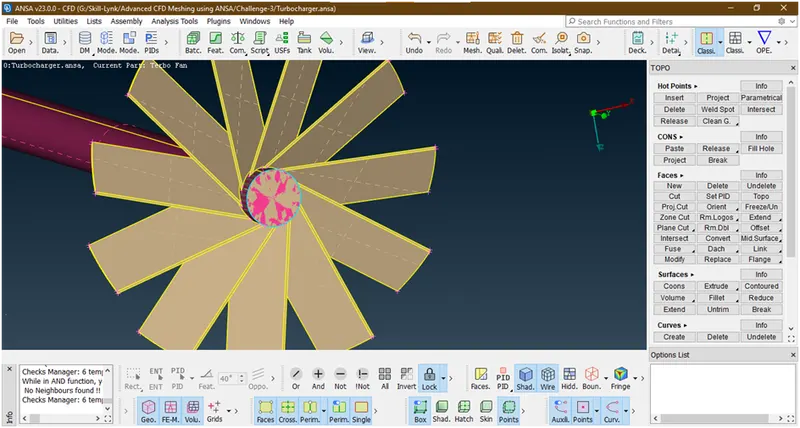
delete the surface which shows above.
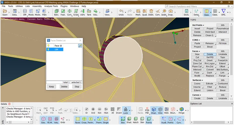
Lets try to delete this circular plates
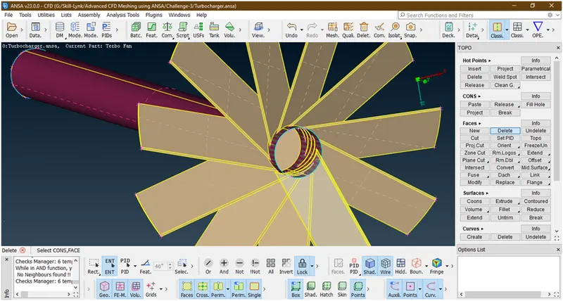
Lets hide these blades by using not
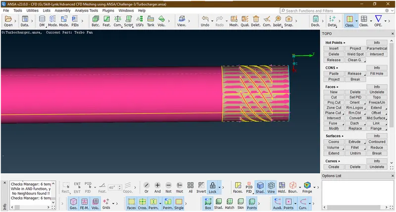
- Lets try to delete this overlapping surface
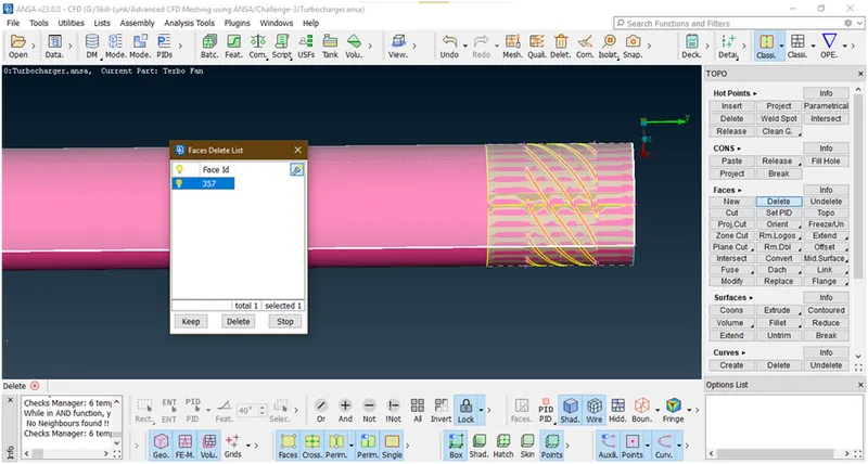
When we are trying to delete this overlap portion, its delectated total body which we don’t want to execute . so for that we are cancelling delete option.
- Lets try to hide above surface lets see
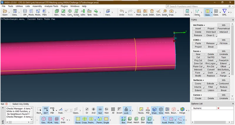
Its means a some portion of pink part is going into grey part so now we have to cut this section
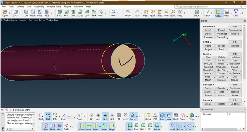
Lets hide this and see the double con is on the surface or not
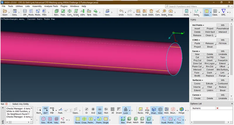
Its not so lets project this con on pink portion
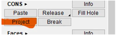
Select the coon
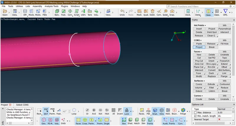
Now selecting entity where we want to project this con
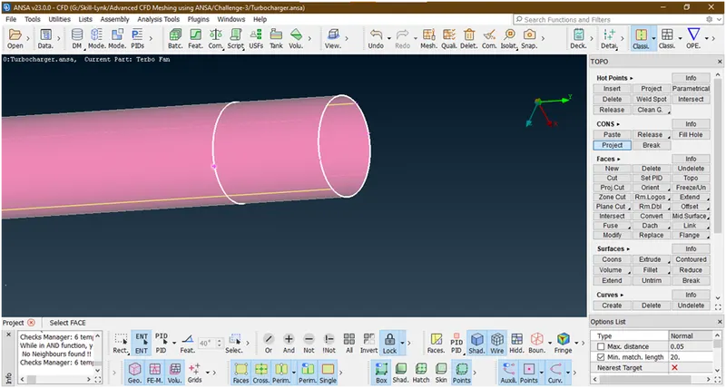
Hit the middle click.Now the con has been projected
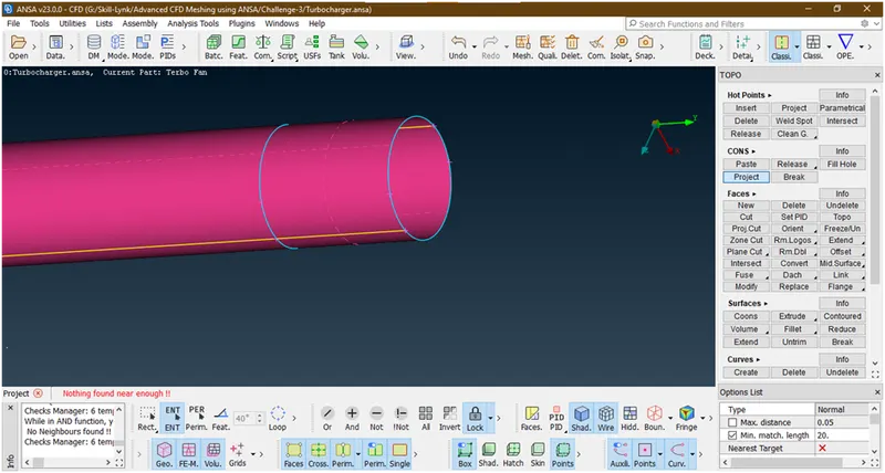
Now delete these faces
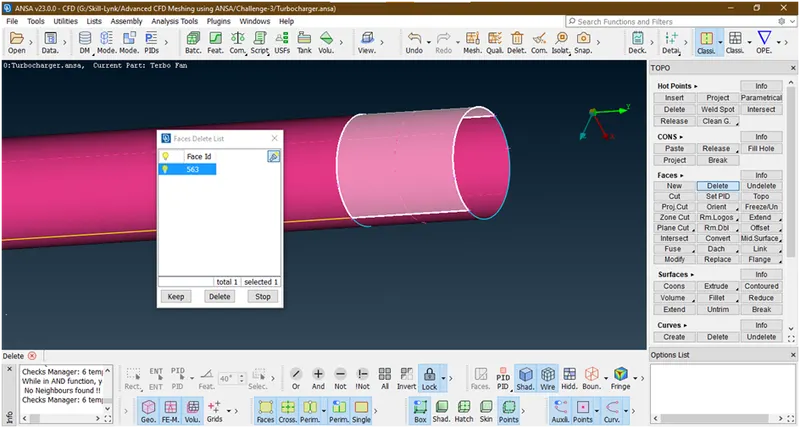
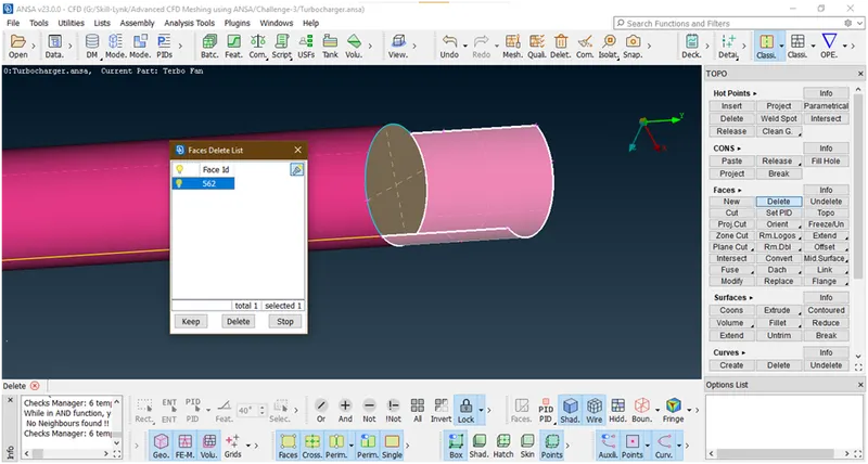
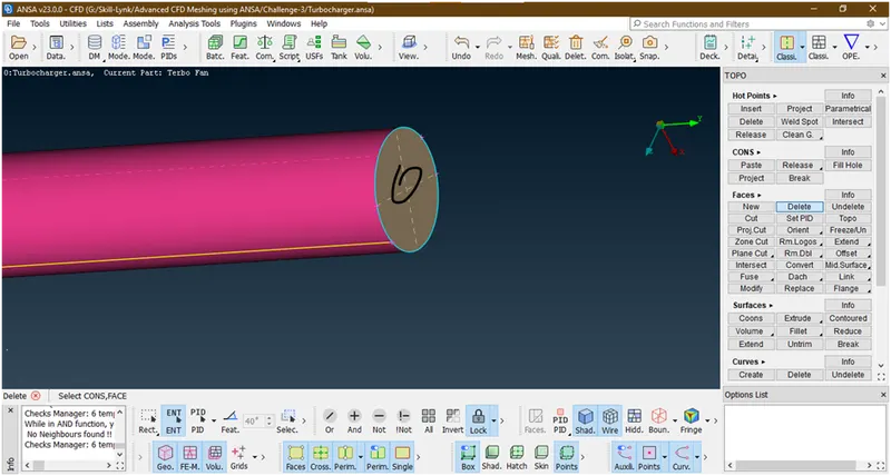
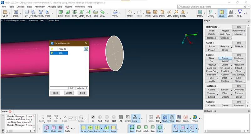
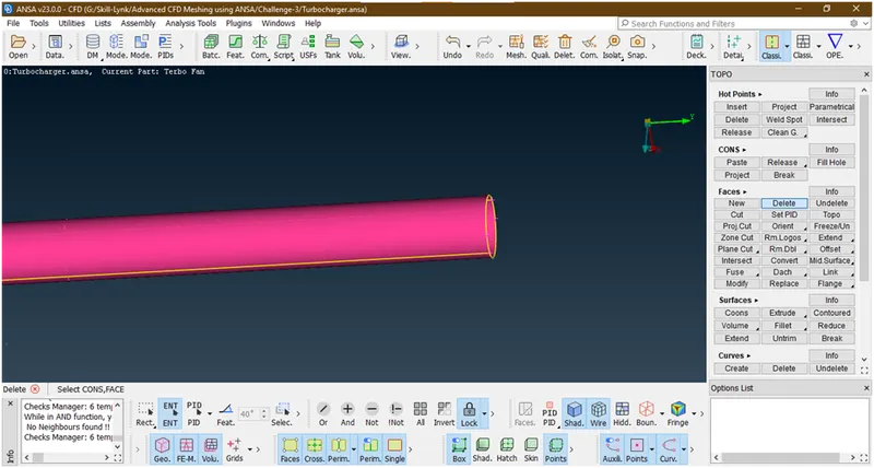
Now its clear.
- Click on all
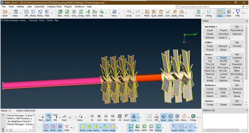
The overlap surface is gone.
Now we have almost clear all triple cons.
- Lets again check any error remaining this part
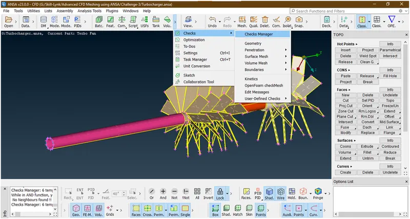
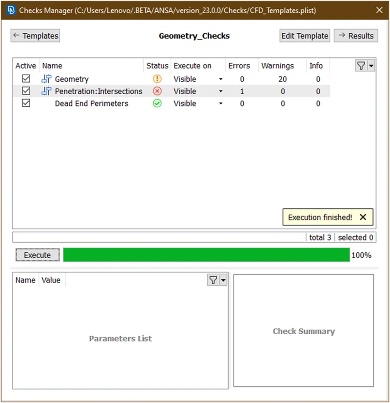
Lets see where the interaction error shows
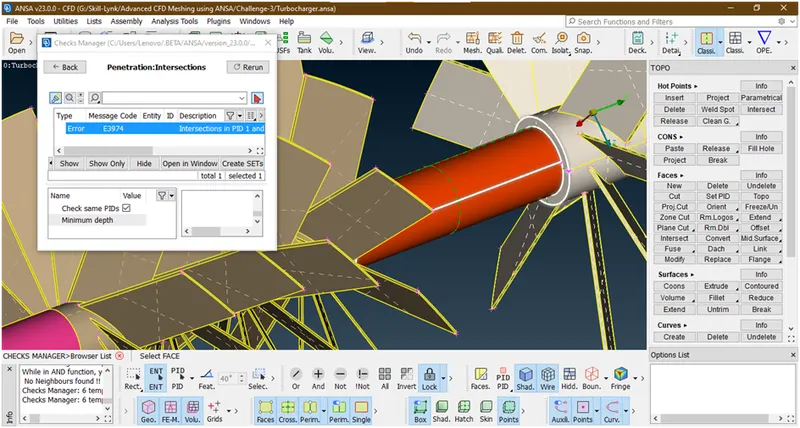
This shows here .lets see why this is come
- Lets hide all other parts and concentrate on this orange part
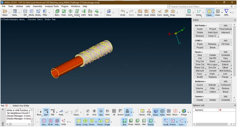
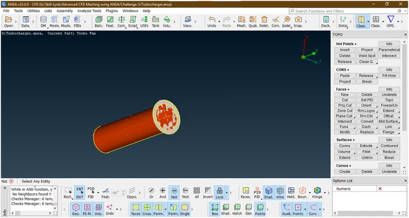
Lets try to delete these plates
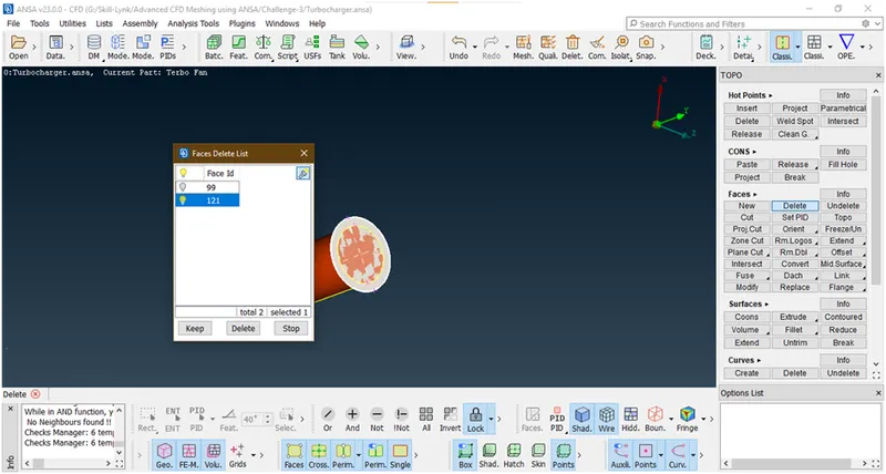
After this single con comes.
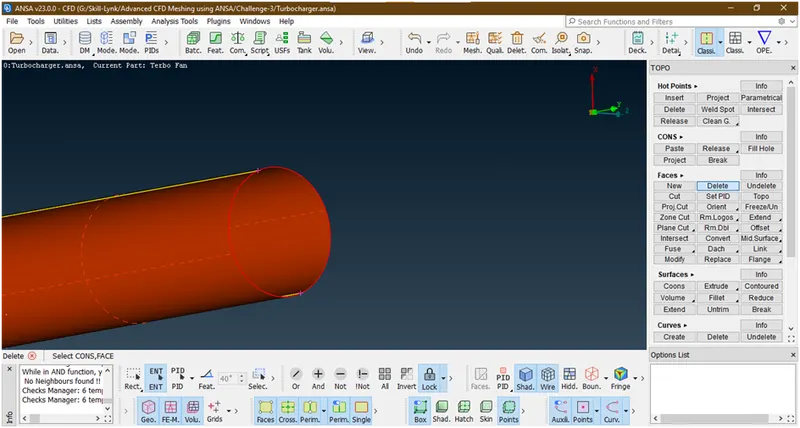
Lets click on all
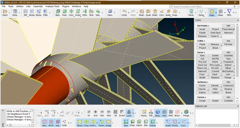
This single con comes. Lets try to make a surface there
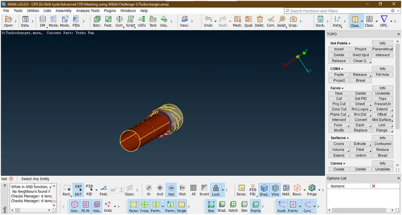
I have hide all other parts by using not tool
- Goto new under faces->Select coons->Select entity selection
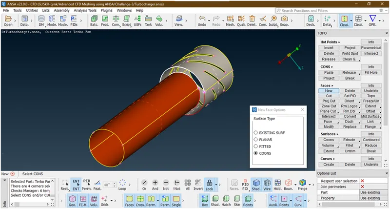
Hit middle click the preview is showing
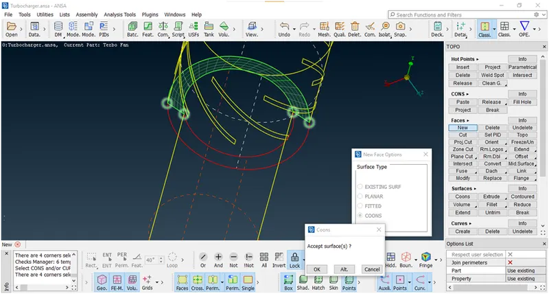
Now showing correct geometry.click on ok
A new popup opens
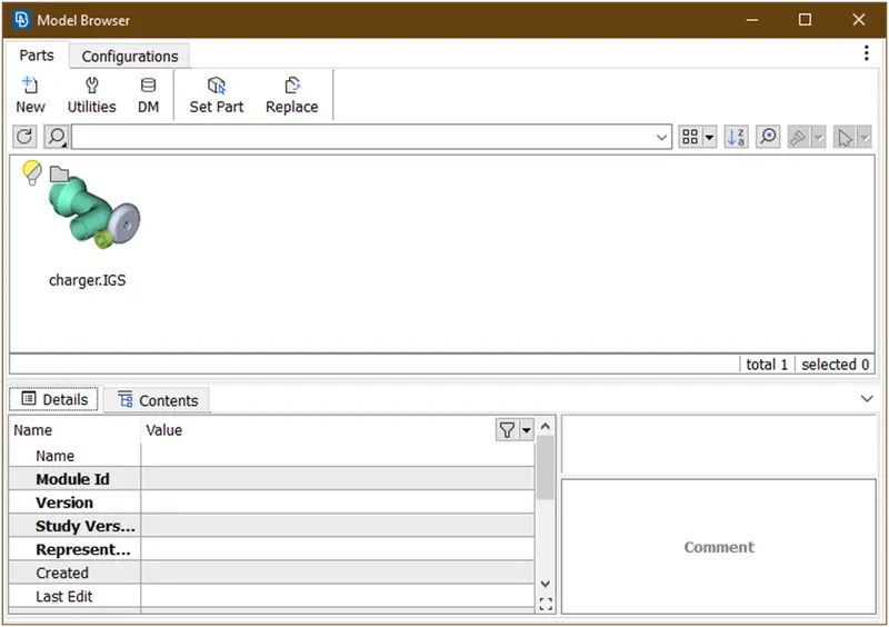
Close this
Again a new popup opens
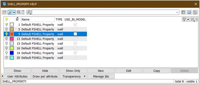
Select this one and close this.Now again create a face for remaining portion by similar method.
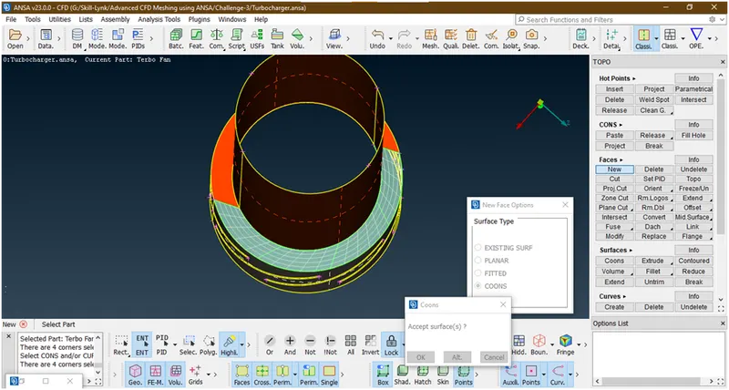
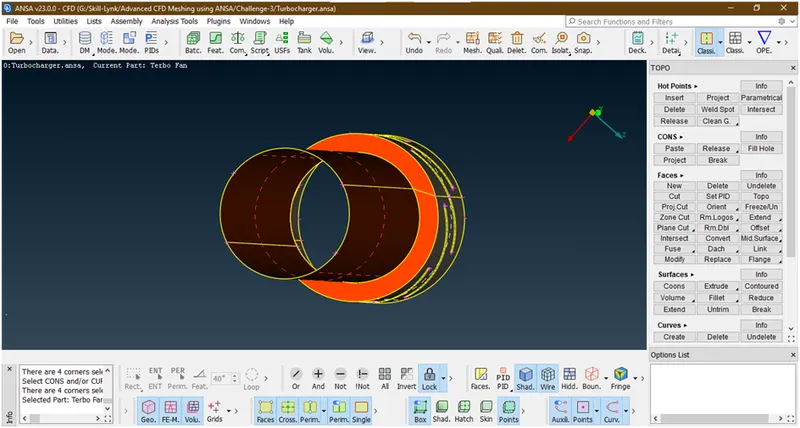
Now it has been created.
- Lets check for any error present
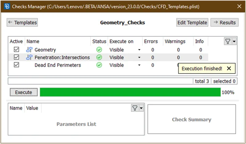
Now we have cleared all errors inthis portion.
- Lets click on all.
- Lets remove lock.
- Then again click on all to show all geometry.
- Lets again check for errors
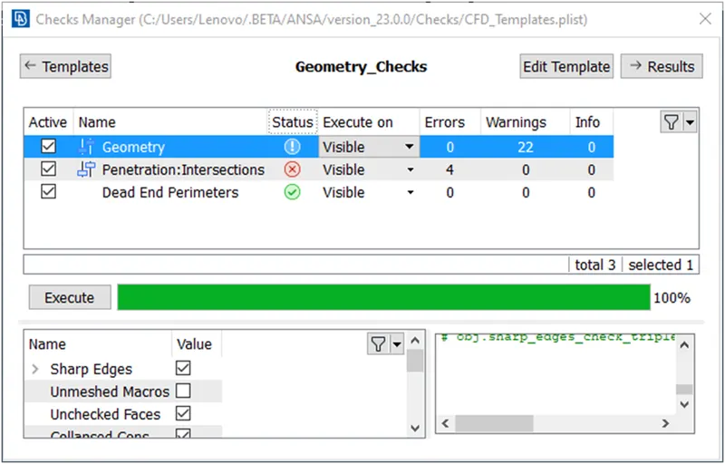
- Lets geometry errors
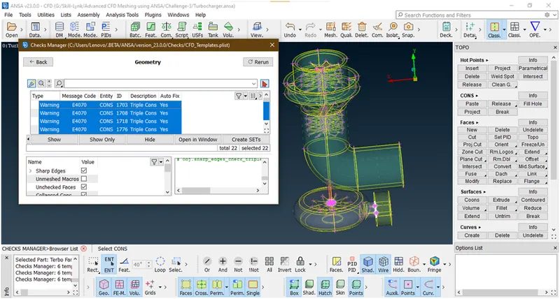
This is at only impeller casing.
- Lets see interaction error
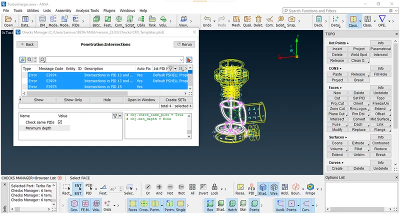
Now close this dialog box.
- Lets clear intersection error here
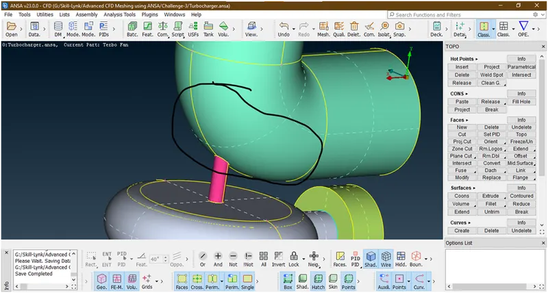
- Lets hide face and see why this error comes
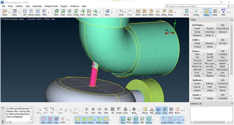
Here some glitches seen. so it means there is a overlap surface.
- Lets try to delete these faces.
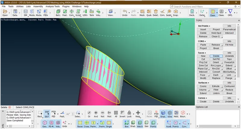
Now it has been deleted
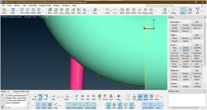
Now let click on all
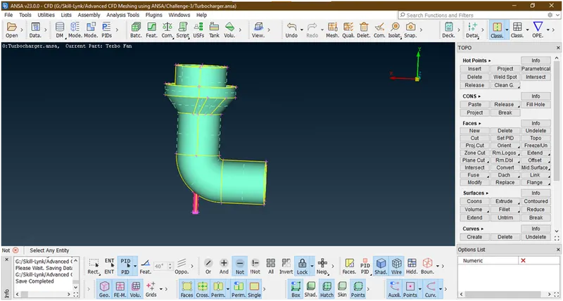
again check for error is removed or not
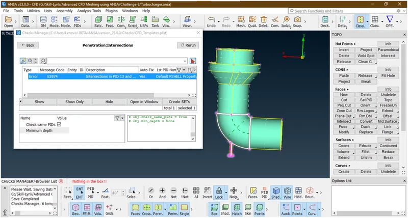
This is not removed. And by understanding this is because of a shaft is goes into compressor casing. lets try to delete this part of shaft.Now this single con is not on shaft so try to project coon on shaft.
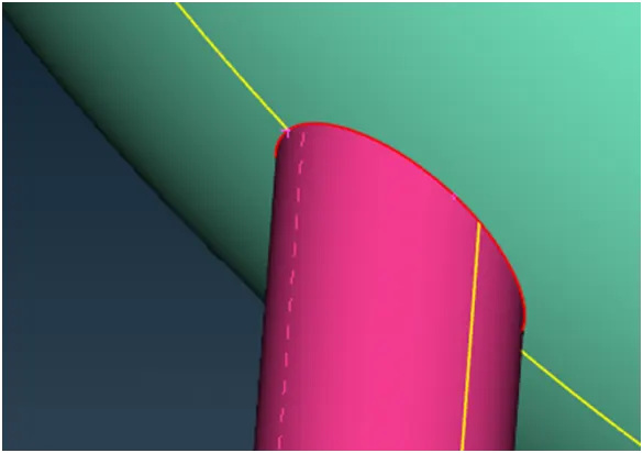
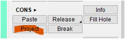
Now select the cons
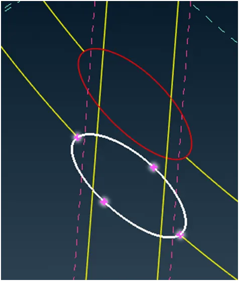
Now select the faces
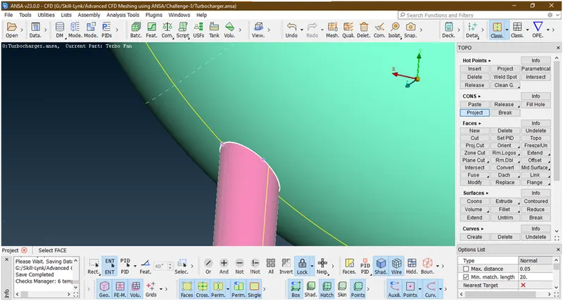
Click middle click
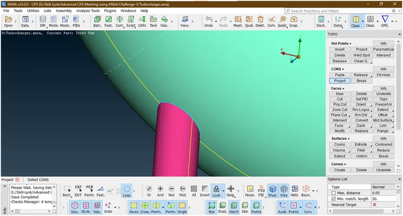
now it become triple con means it has been projected.Lets hide some faces of compressor casing and isolate shaft
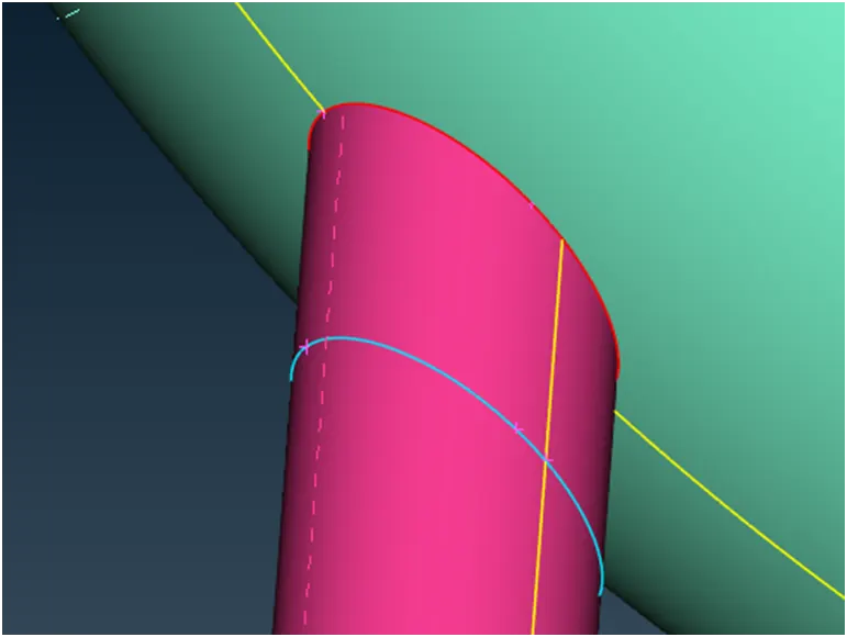
Similar procedure follow to project this single con on shaft
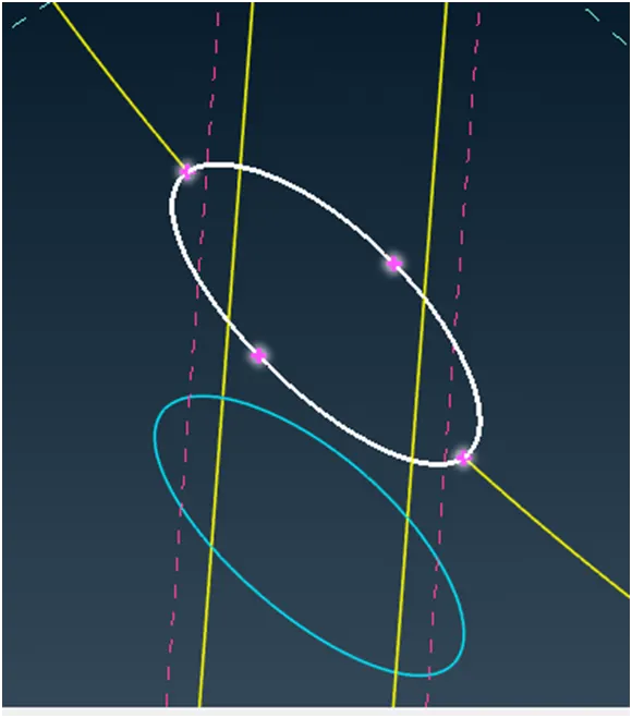
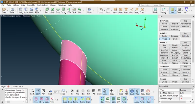
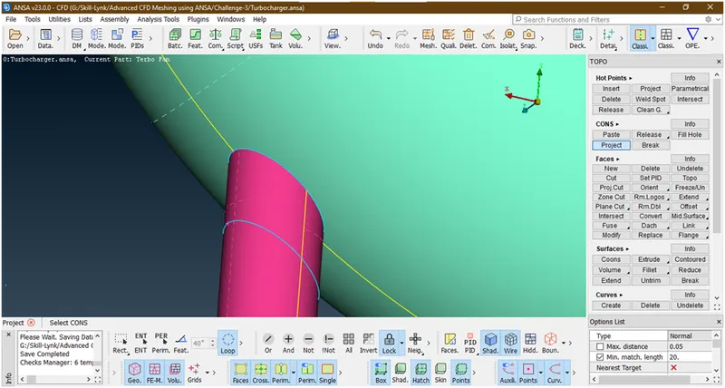
Now click esc.
- Now try to delete this part of shaft
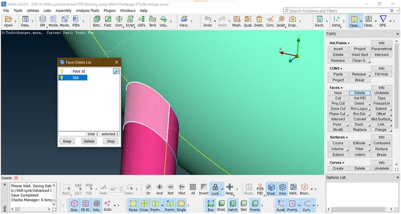
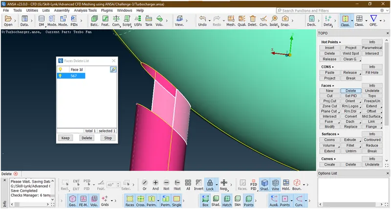
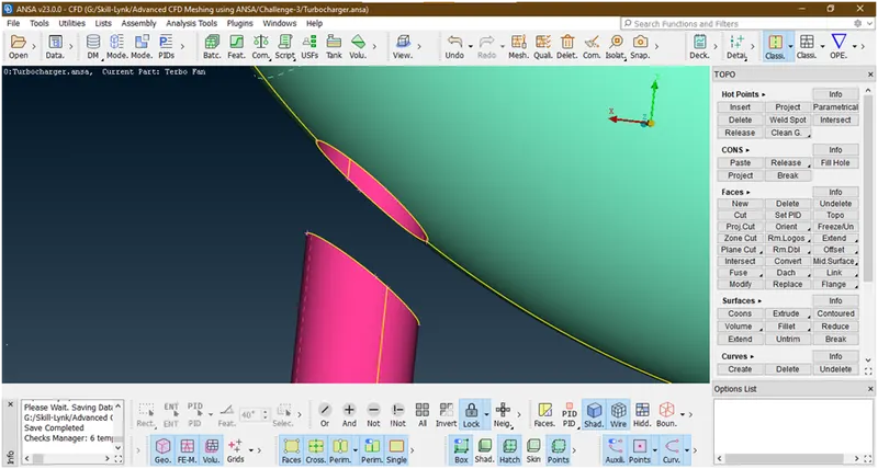
- Now click on all and again check for intersection error is removed or not in this part.
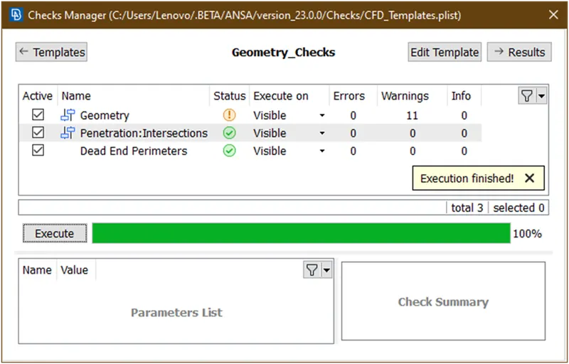
- Lets go for next section by hiding compressor casing ,blade stage-1,blade stage-2 i.e. goto turbocasing part.
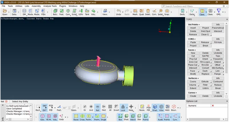
We have hide all other parts and Put a lock.
- Lets check errors in this part
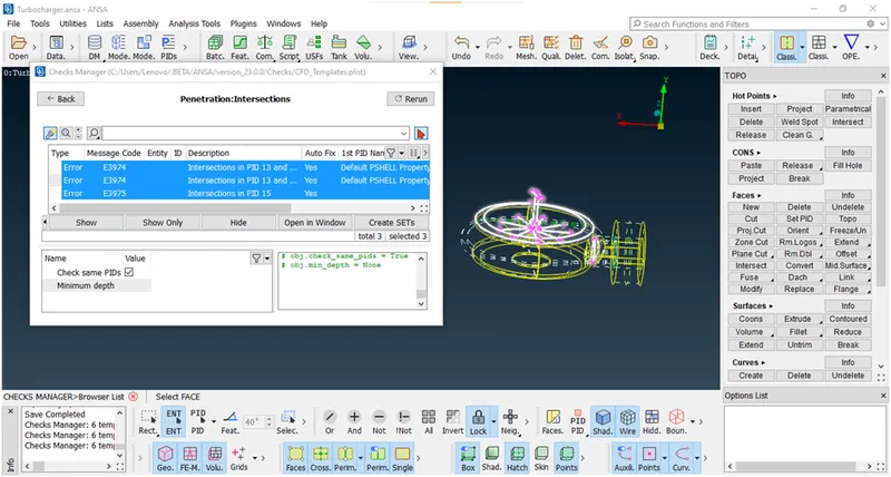
Lets clear this errors.
- Lets hide this inlet valve by using not tool and pid selection mode
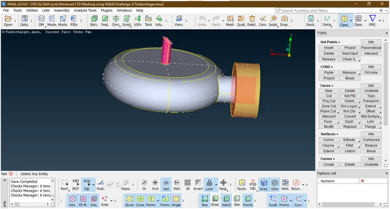
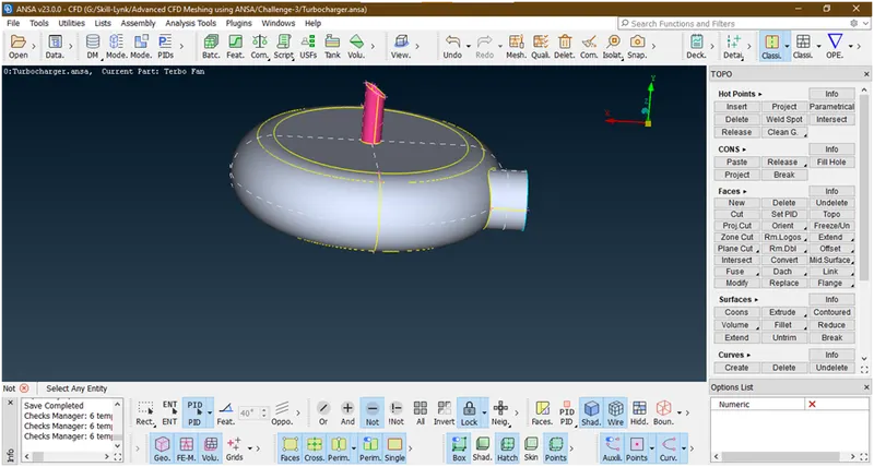
Now lets hide top surface of turbo casing and look into the casing why error occurs. For that use not and selection entity mode.
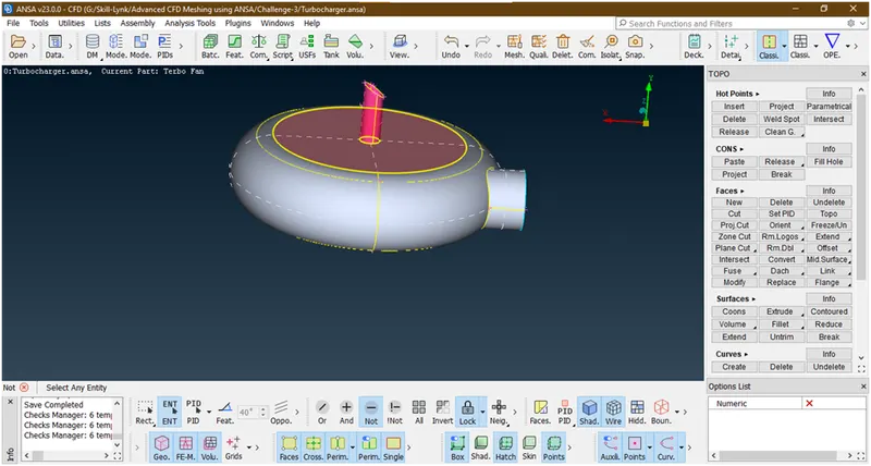
It has been hidden.
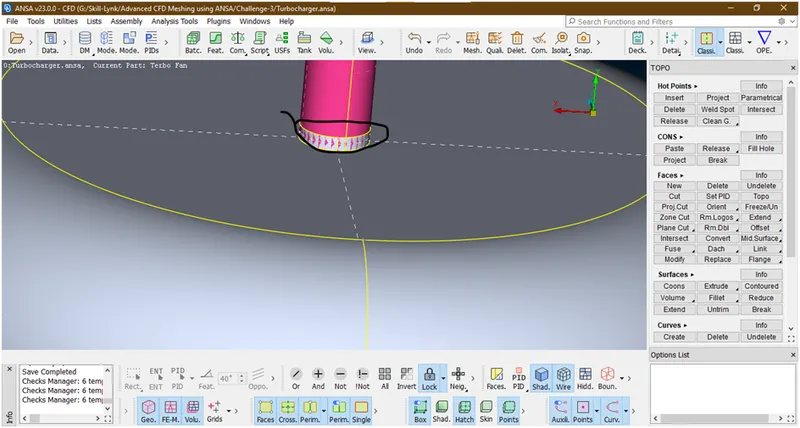
This looks like a overlap surface.Lets hide another surface
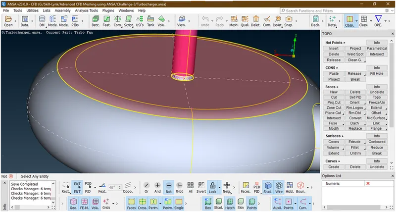
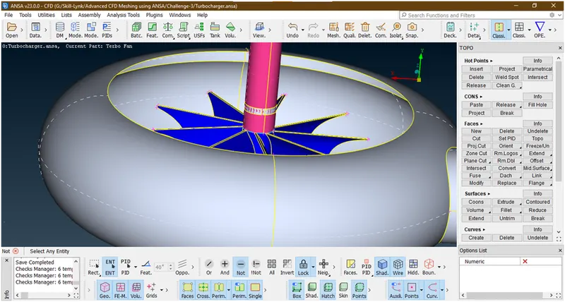
This overlap surface occurred. And also this is due to shaft goes into impeller section. Firstly hide surrounding surfaces.
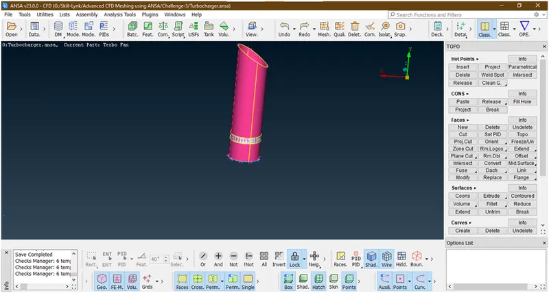
Try to delete this overlap surface
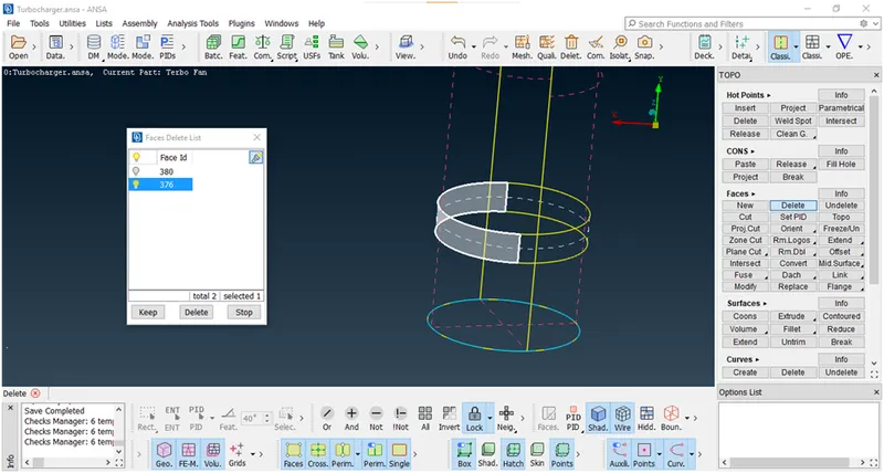
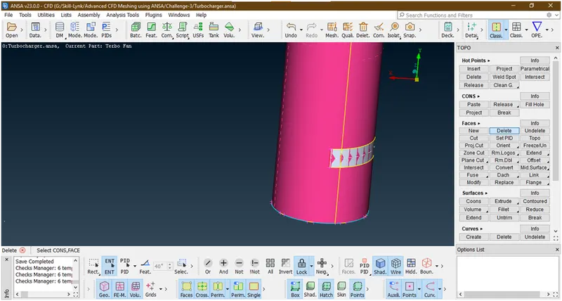
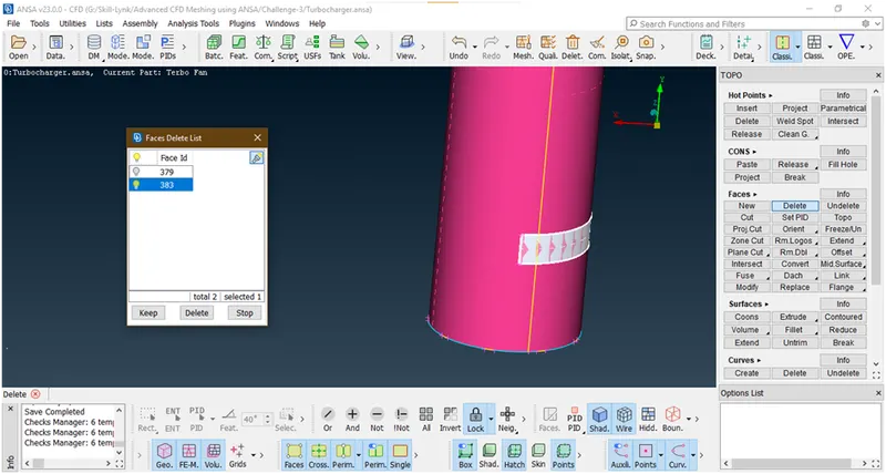
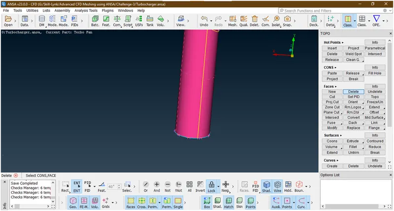
- now its deleted.Lets click all and check for error is removed or not
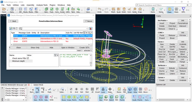
Its not removed because shaft goes into impeller casing. Try to cut the section of shaft which creates intersection error.
• Lets hide all other faces .
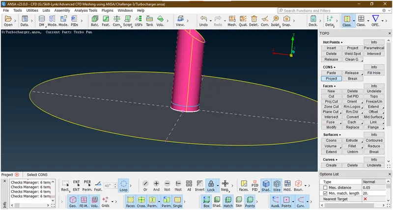
• Project these cons from impeller top surface on shaft to crate boundary.
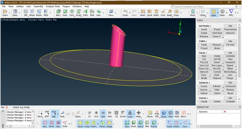
Selecting cons
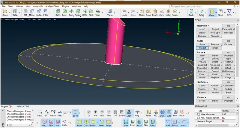
Selecting faces
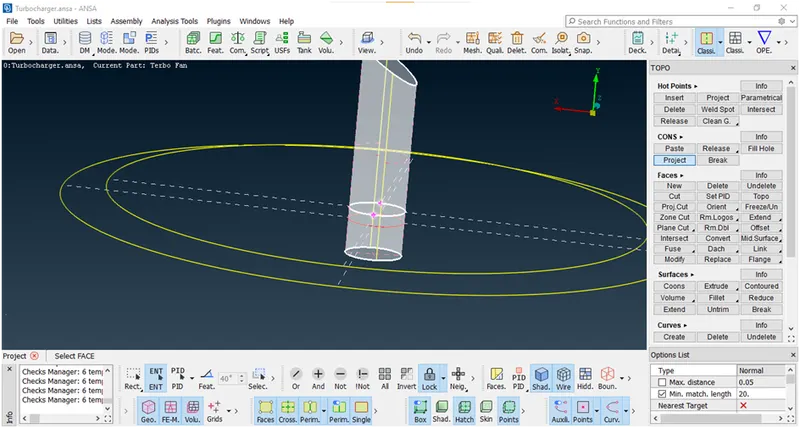
now its created.hit the middle click
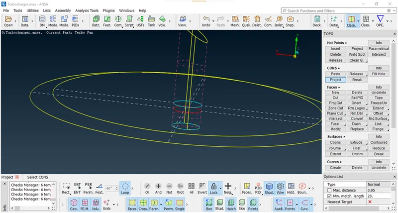
Now let project 2nd single con by hiding this surface.Follow the similar procedure as above for projecting this coon on shaft
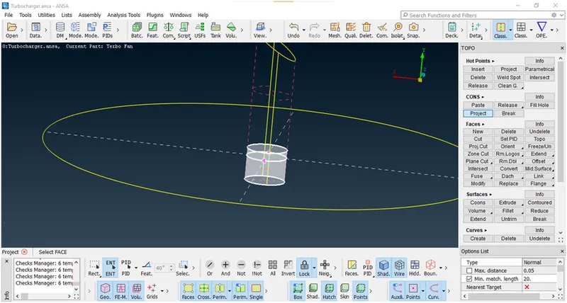
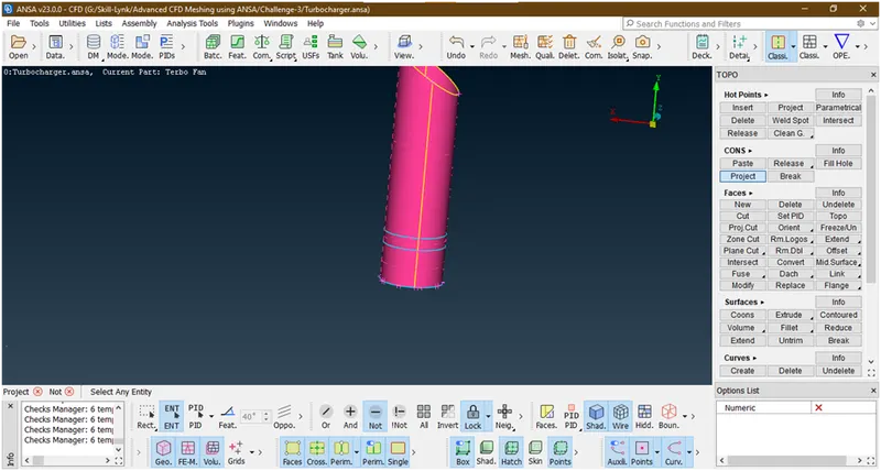
- Lets try to delete this section.
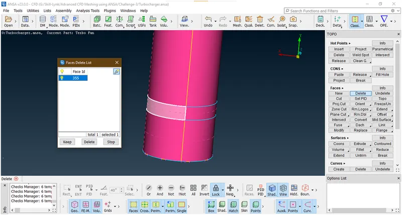
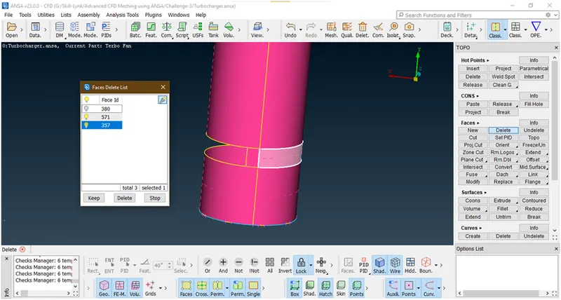
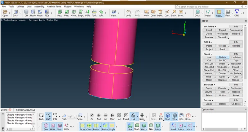
Its remove.
- Lets click on all and again check for error
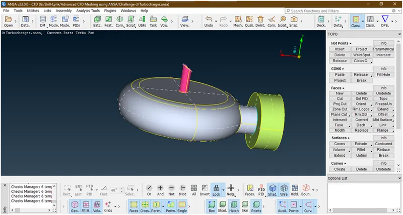
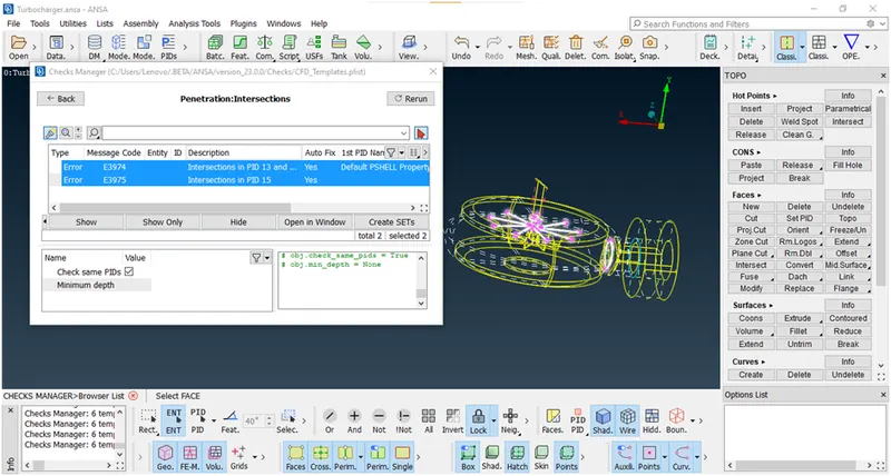
- Now its clear lets go for next error i.e. impeller blades and shaft
- Lets isolate blades and shaft
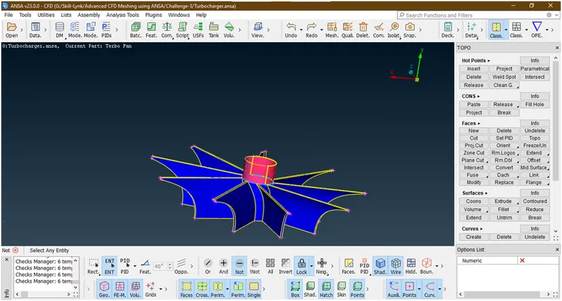
- Lets check where error occurs
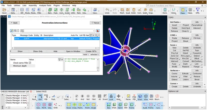
- There is some glitches shown
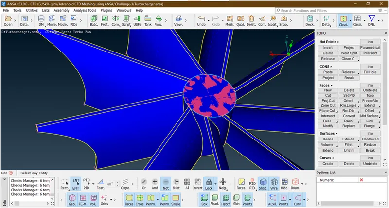
- Now try to delete this surface
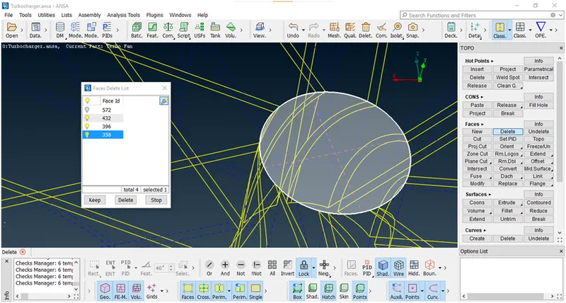
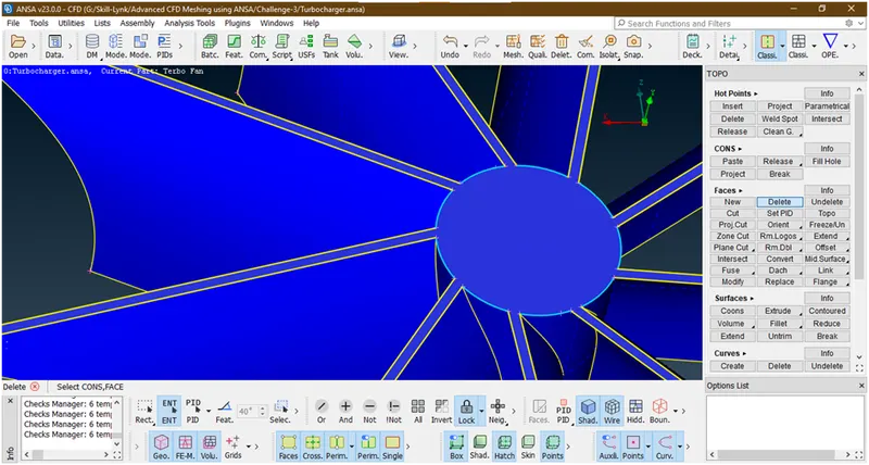
Now try to delete this plate
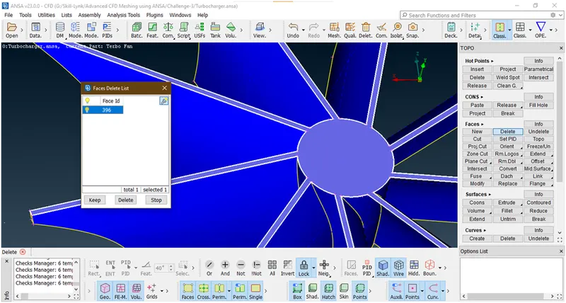
When we are trying to delete this plate it select the total surface so let first cut this section from blades. Cancel this delete opration and let see what we can do.
- Use and tool to show neighbour surface of cons
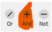
Now select cons
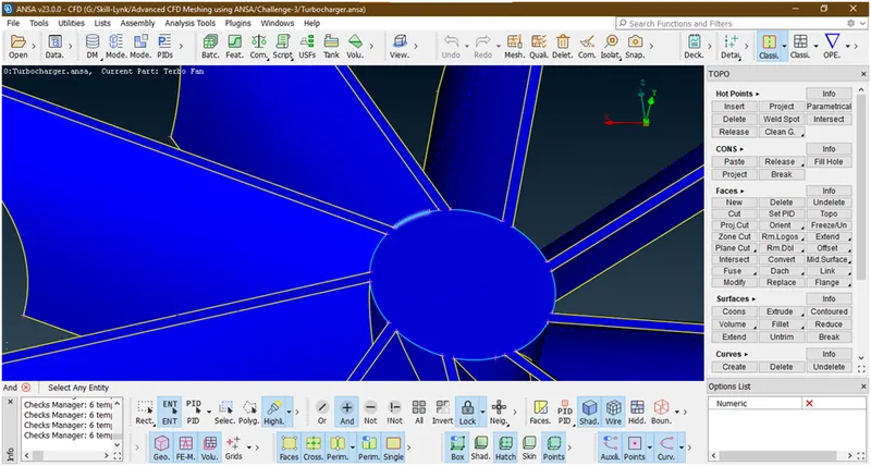
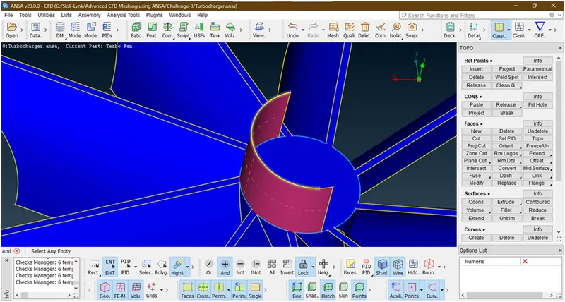 Select other side con
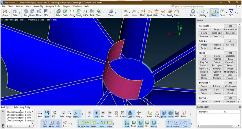
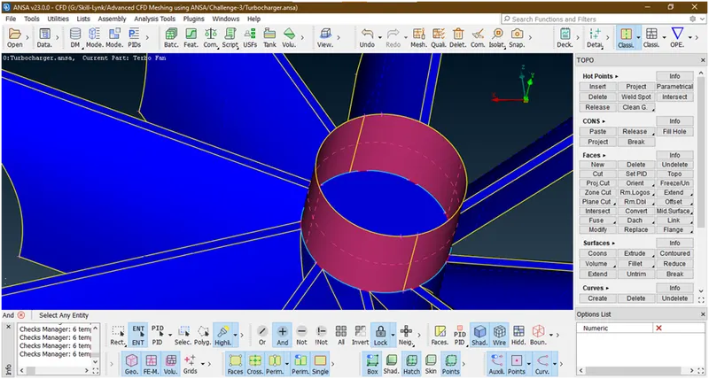
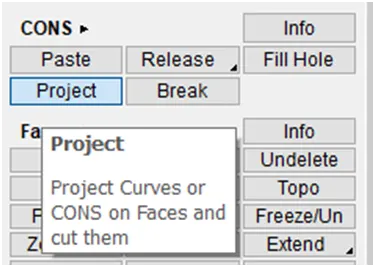
Now try to project con to blades surface
Now select the coons
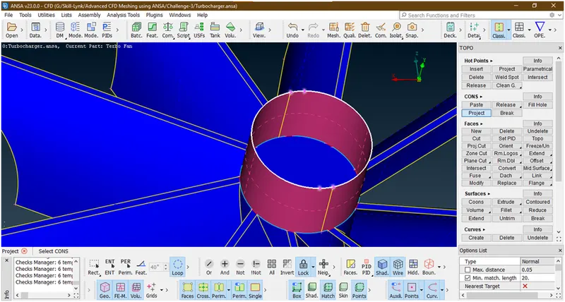
hit middle click.Then asking for selecting face
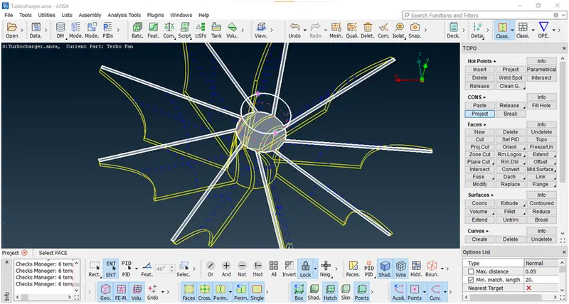
Hit middle click.Now its created.
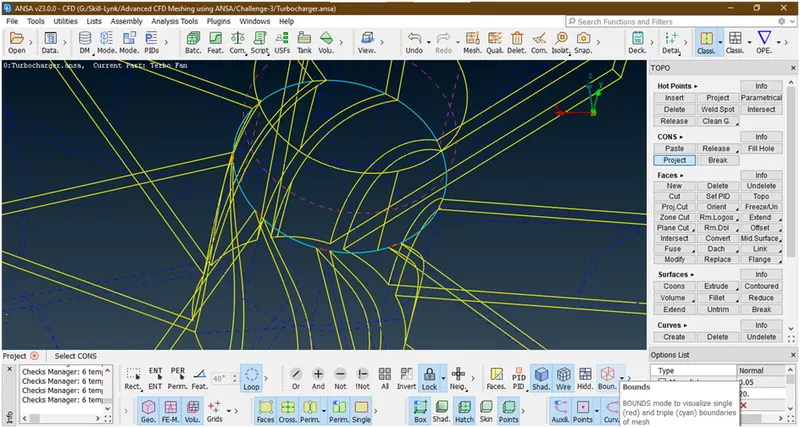
Now let try to delete this section
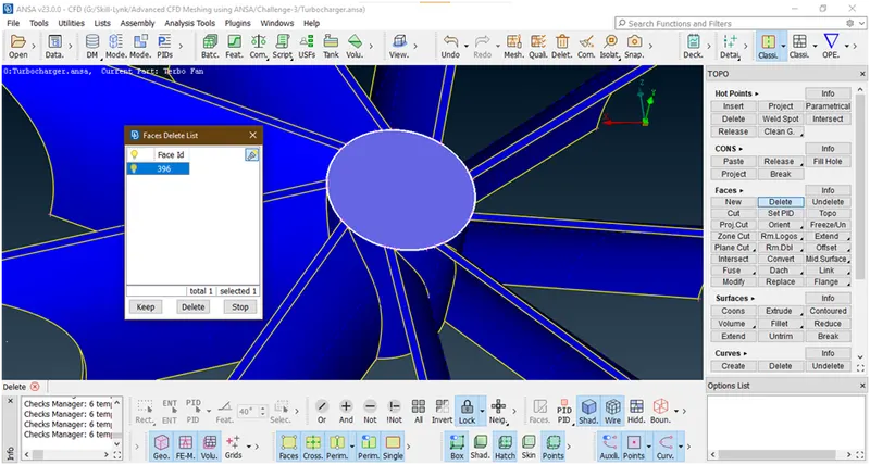
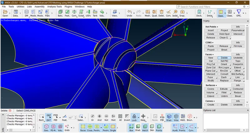
Some single cons seen here.Lets hit topo here to autofix
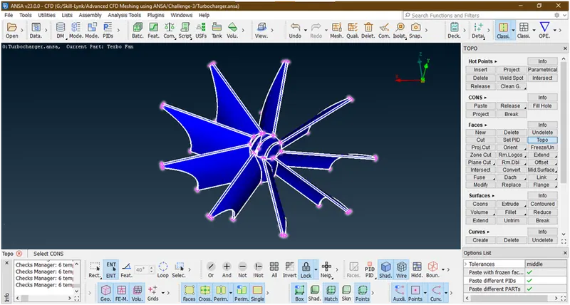
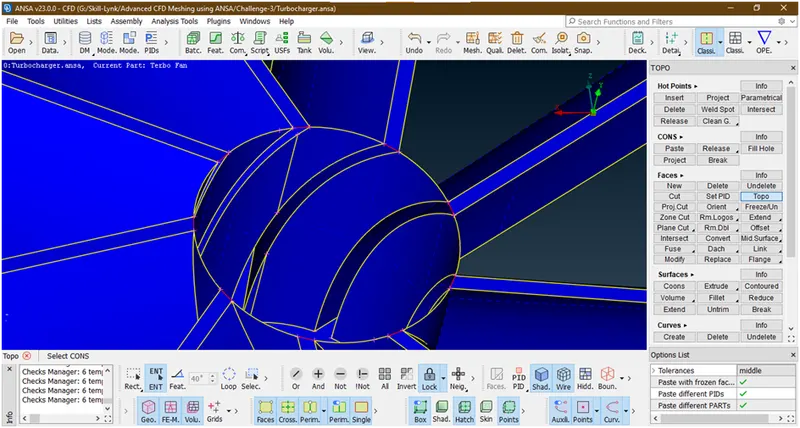
It can’t get fixed.Now lets show shaft by using and tool
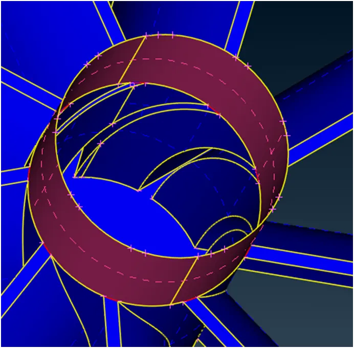
Lets delete these unnecessary hot points by using delete tool under hotpoints and select points
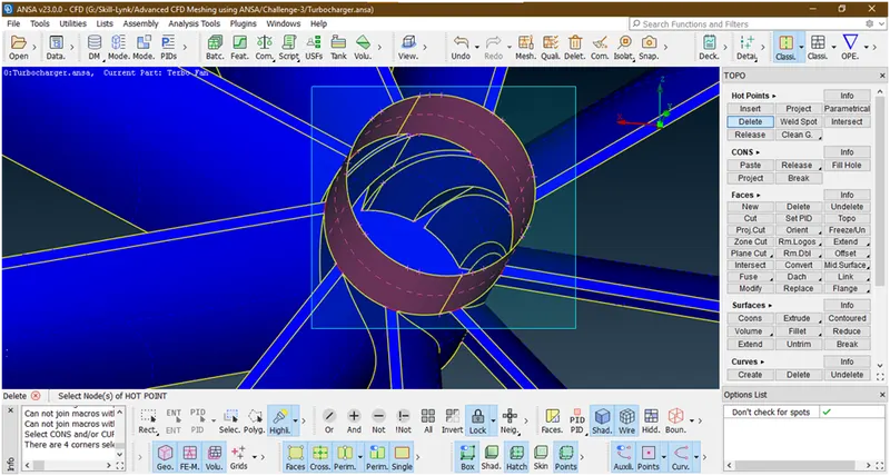
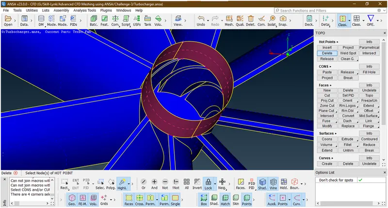
Now project these single cons on blade surface
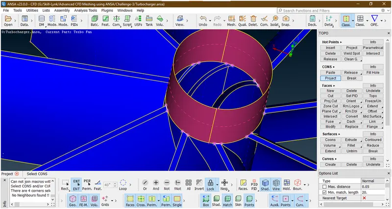
Now select the faces
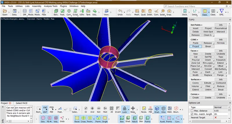
Hit the middle click for execution
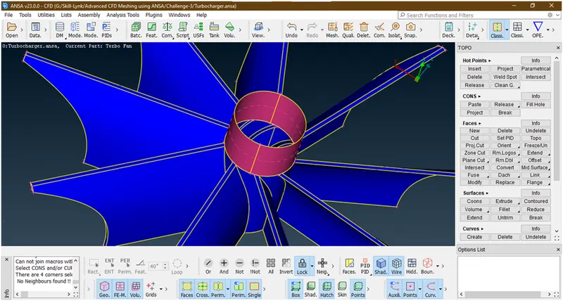
Now its done.
- Lets check for errors
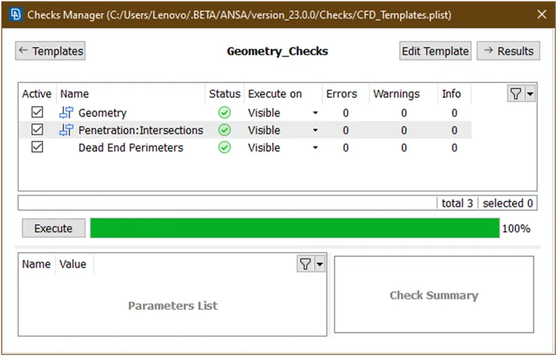
Now we have clear all error in this section.Lets click on all
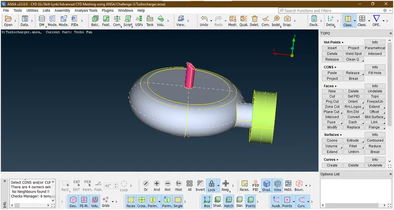
- Lets again check for errors
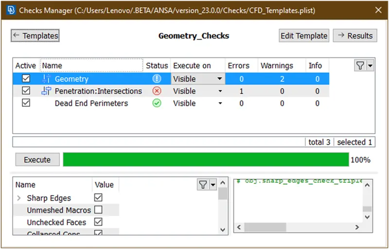
Lets see geometry error
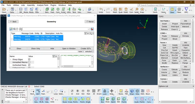
Here it is let see why these triple cons come.Let hide all other parts
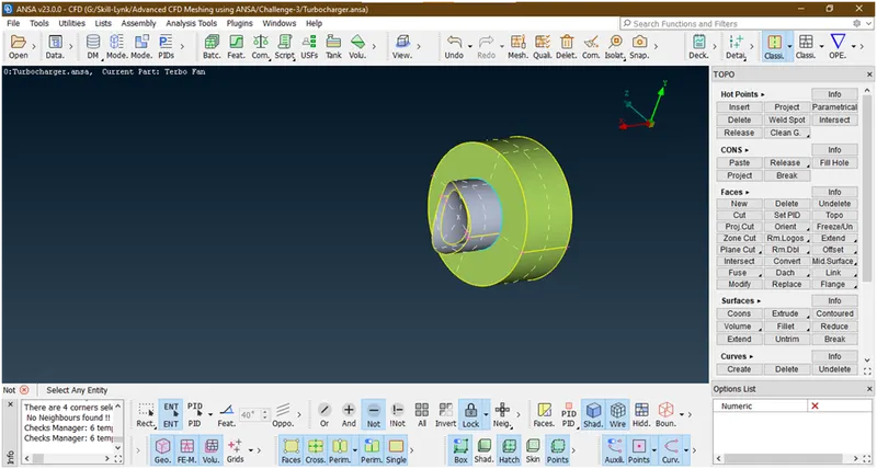
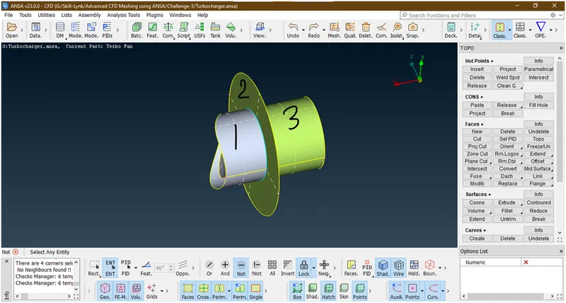
Now this is because of above 3 surfaces are mating. So it is necessary part. We are ignoring this.Click on all
- Now lets see intersection error
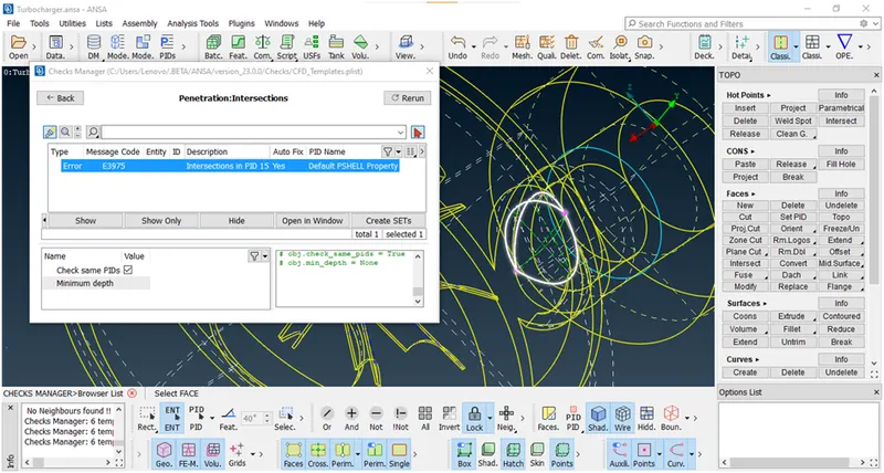
Lets clear this error by hiding all other parts
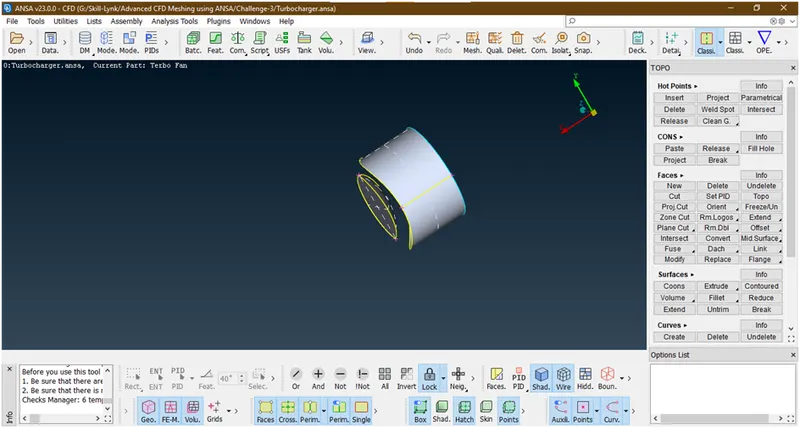
Lets see which part is causing intersection error
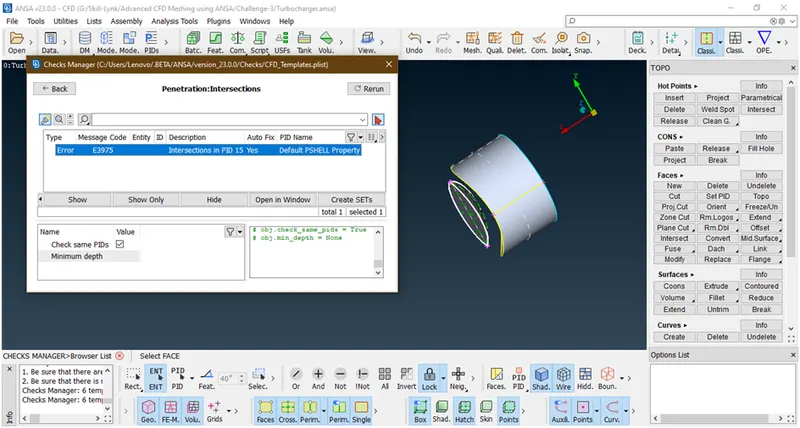
This part which is selected.Try to isolate this
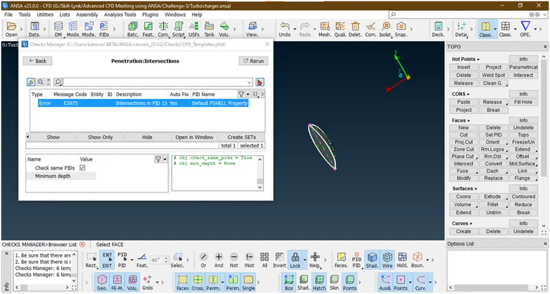
Goto universal delete option
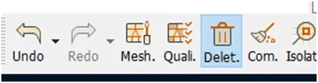
Box select the entity
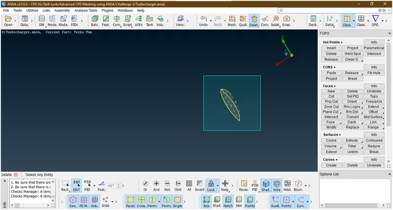
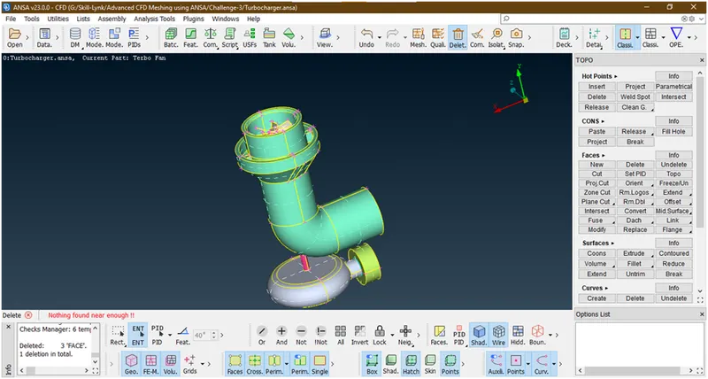
Now it has been selected.Hit middle click to execute.New popup opens
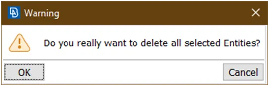
Click on ok. now its deleted.
- Lets remove lock and click on all tool
• Lets check for errors
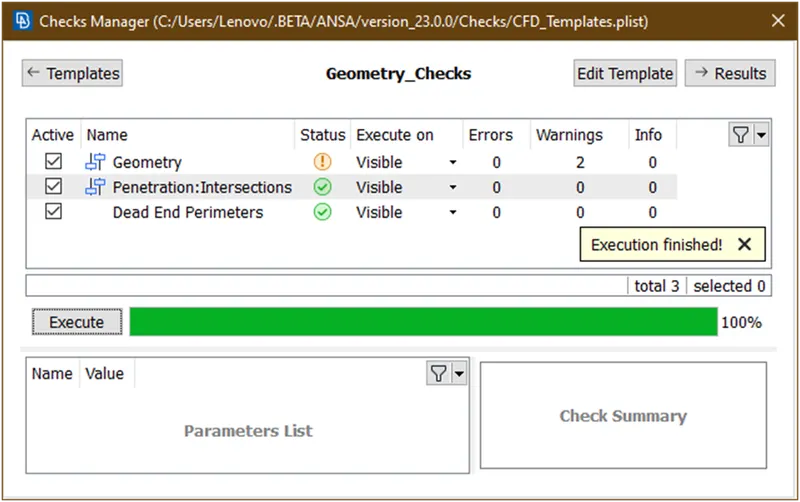
Now we have successfully clear all intersection error.
• Lets once again check which warnings are shown in geometry.
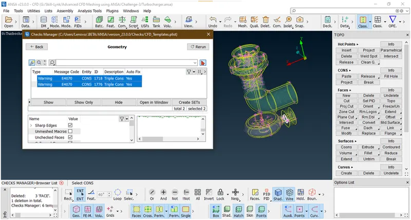
This is required. so we are ignoring.So we have cleared all geometrical and intersection errors.Next step is surface meshing. We need a water tight mesh i.e. fully closed mesh for external flow analysis. so for close all openings.
- First close this opening by creating surface there
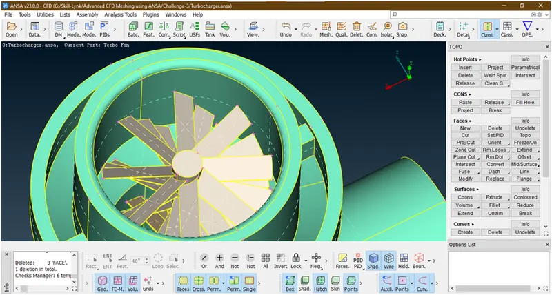
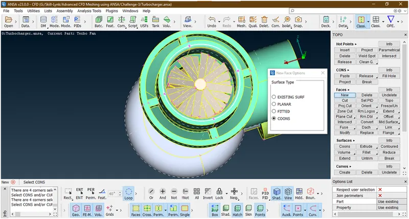
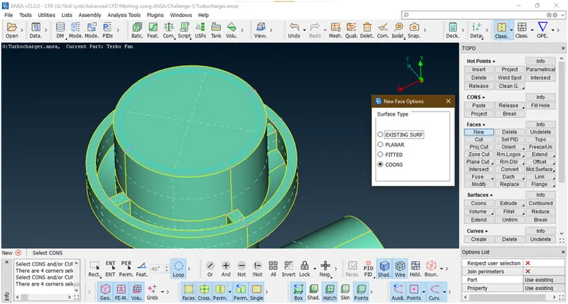
It has been created.
- Lets close another opening
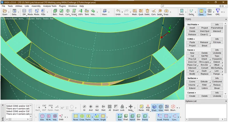
There is a small opening.Lets close this by hiding some portion so that we will able to clearly see

Lets create a new face
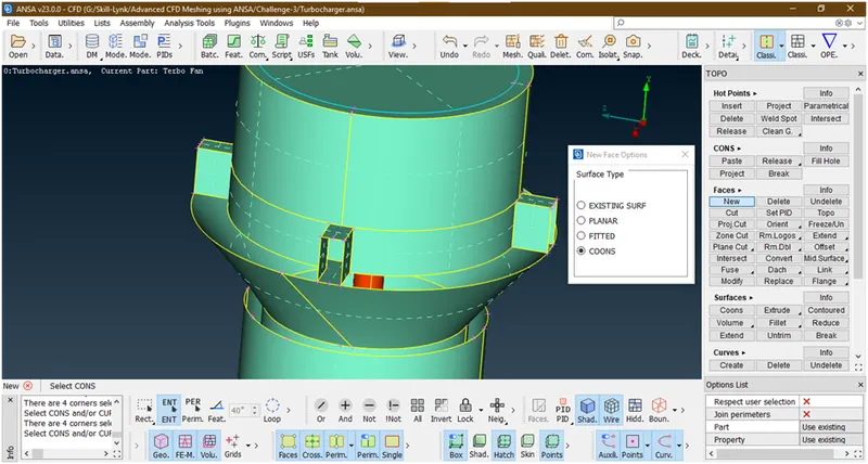
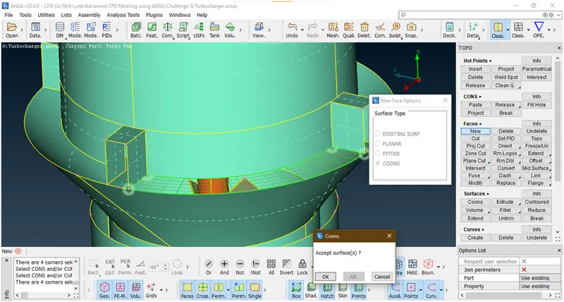
Click ok.
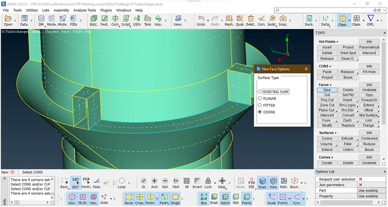
Similarly we are making surfaces around this surface.
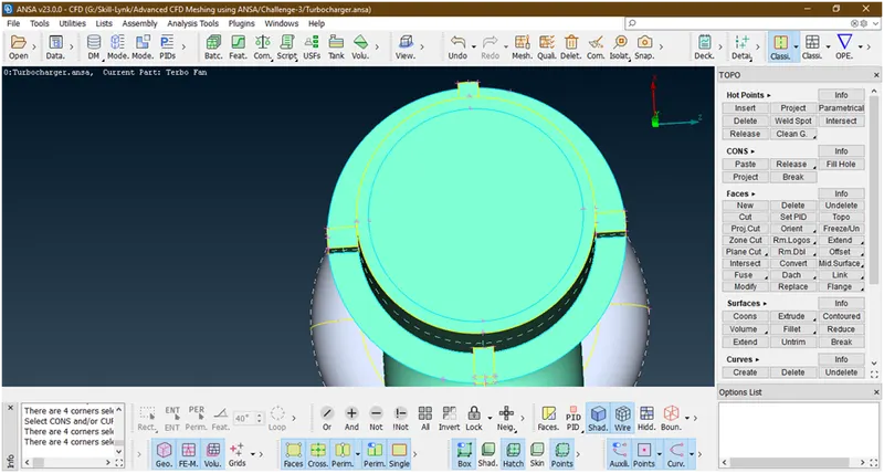
We have successfully created.Now lets do all and Try to close these hole
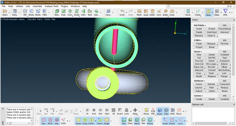
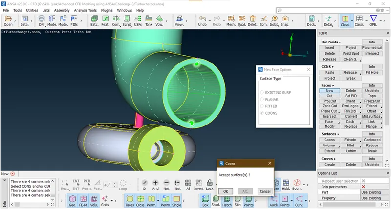
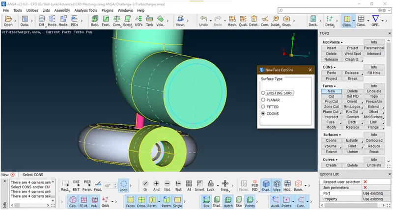
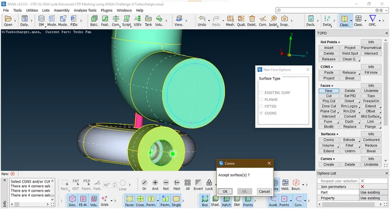
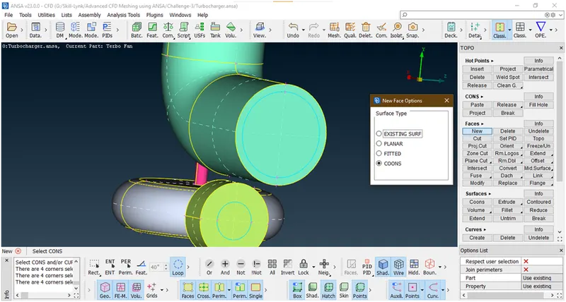
they have created. Going for next hole to close
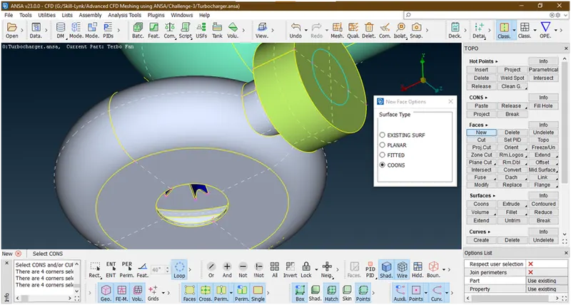
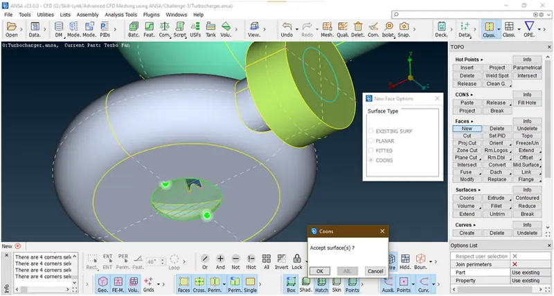
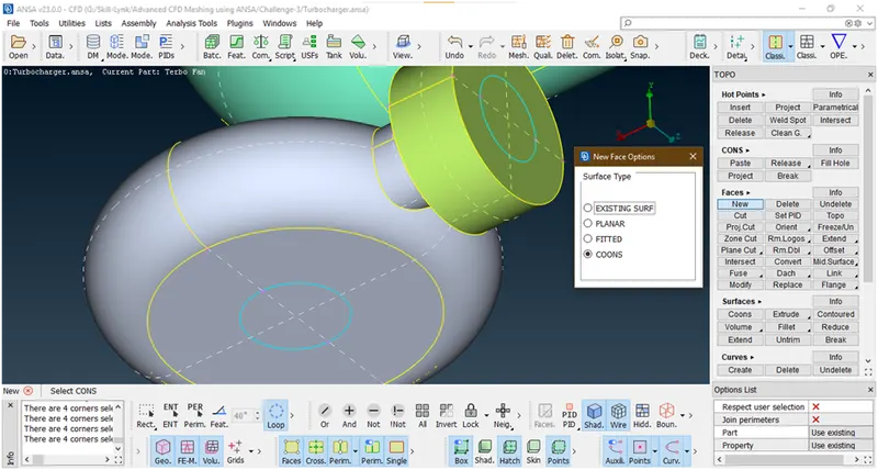
Now we have successfully close all openings.
- Check for any errors
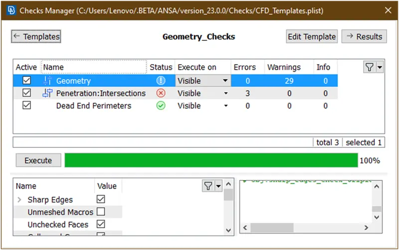
Let see geometry errors
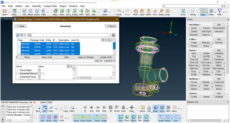
These are triple cons where we have created surfaces. So it is neglected.
Lets see intersection error
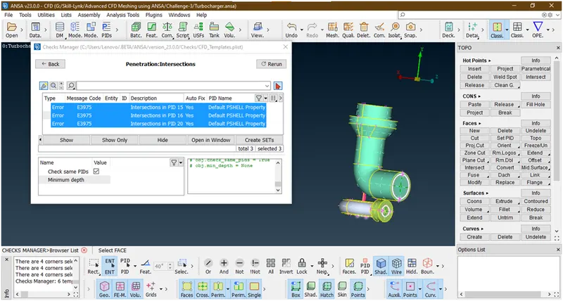
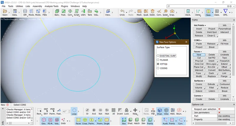
These are there where we have created surfaces. let clear these errors.Let delete these surfaces.
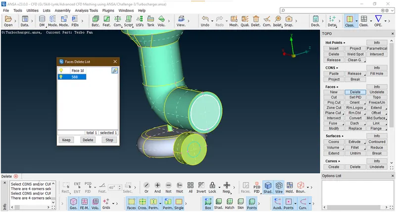
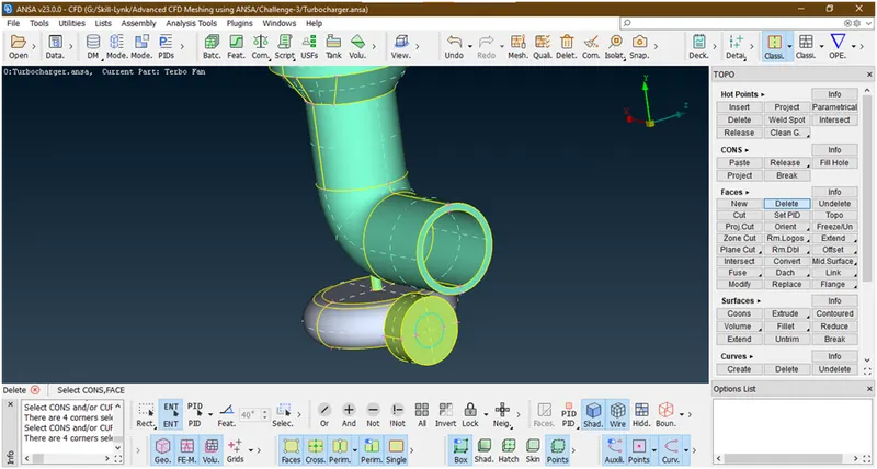
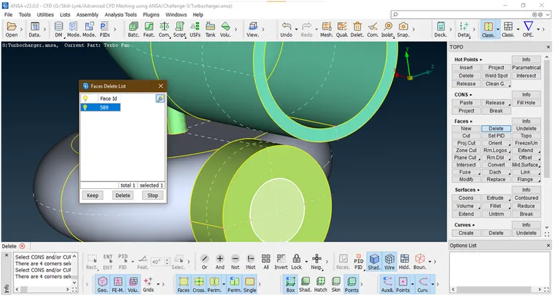
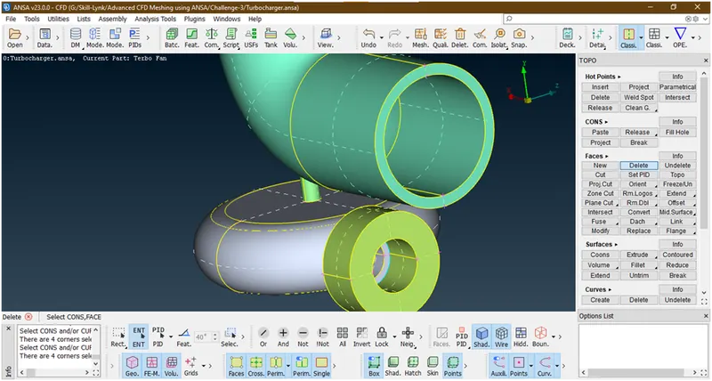
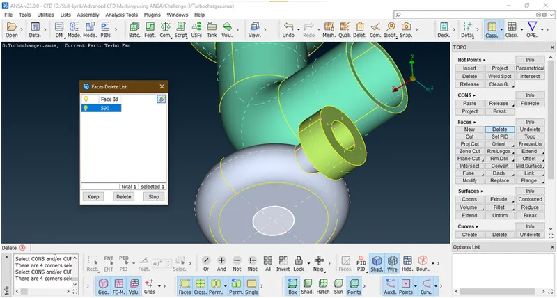
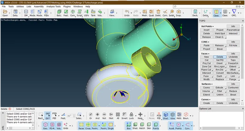
Lets try to crate a new surface by using fitted option
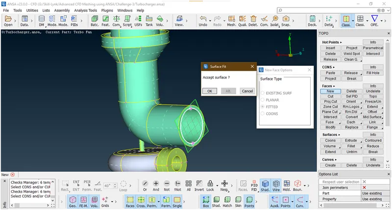
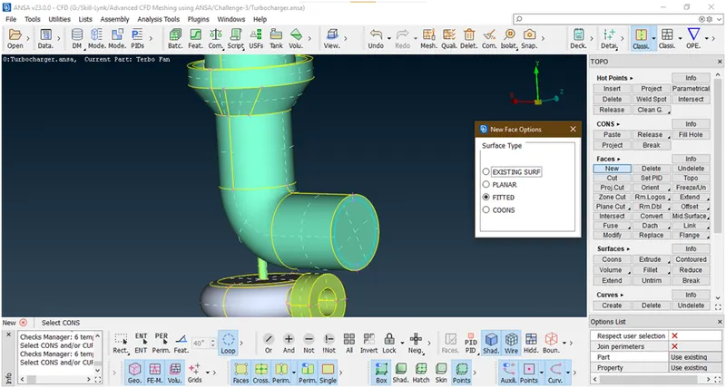
Lets check for any interaction error comes
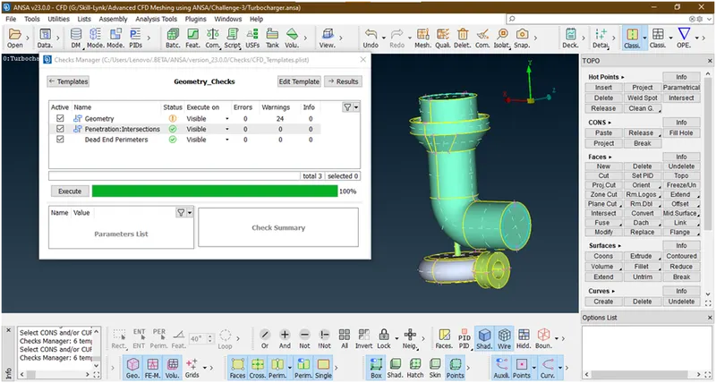
Hurray its clear.
Do same procedure for other openings also
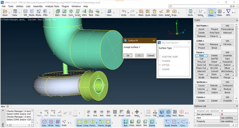
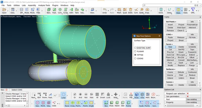
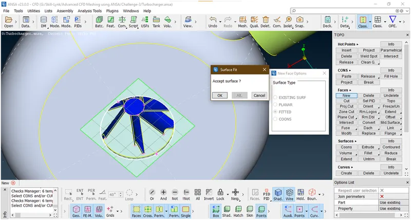
- Lets again check for any errors
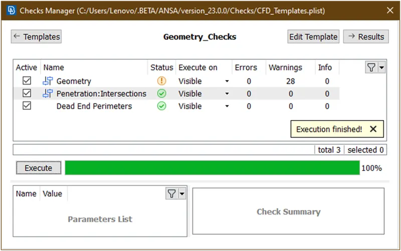
Now, we have clear all intersection errors.
- Lets see geometry errors
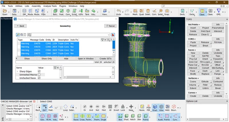
These are the triple cons and these surfaces are required. so we are ignoring this.
- Let assign the pids
Goto the pid manager
A new popup open
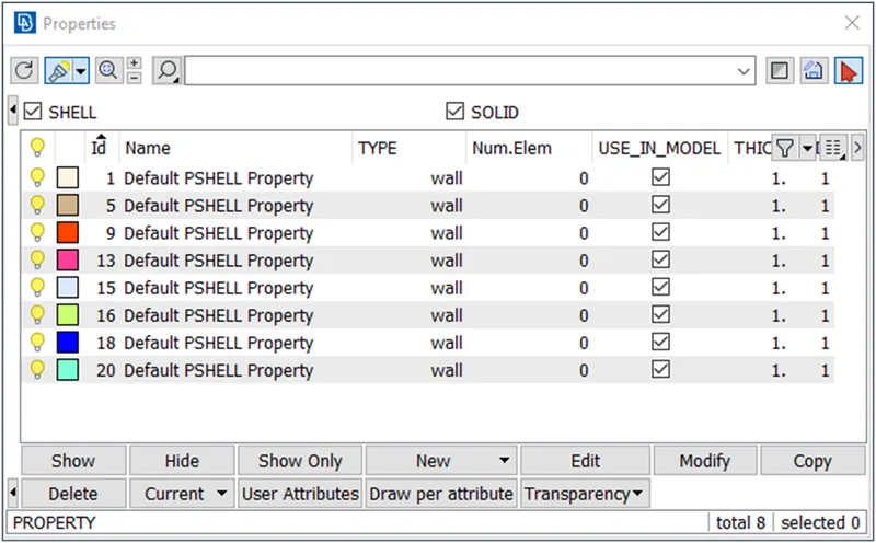
- let assign ‘compressor casing’ by renaming the above file.
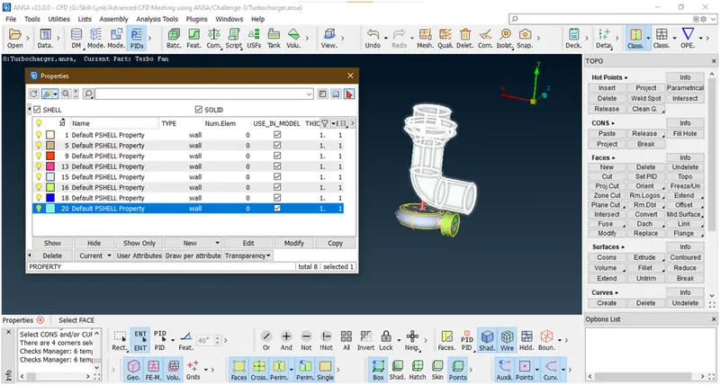
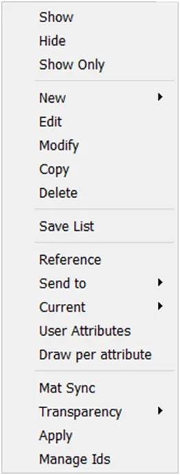
This is compressor casing. Just right click in that the following options are showing
Goto edit, a new popup opens
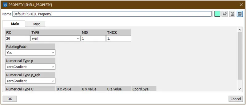
Rename as compressor casing
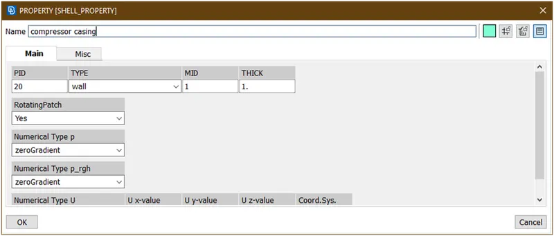
Click on ok
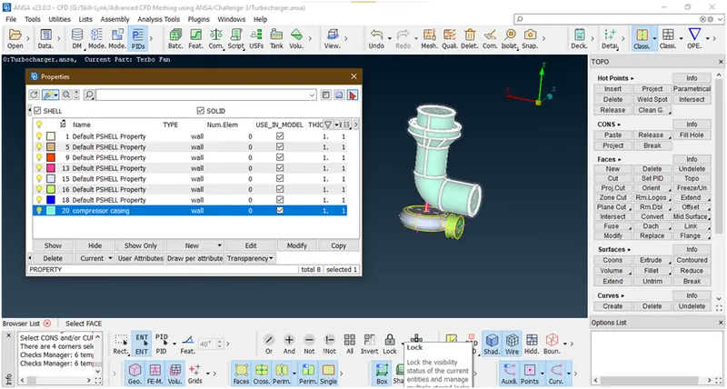
Now its assign.Lets hide this. now follow the same procedure for other component
- Lets assign as ‘inlet casing cover’
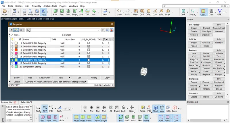
This is inlet casing cover
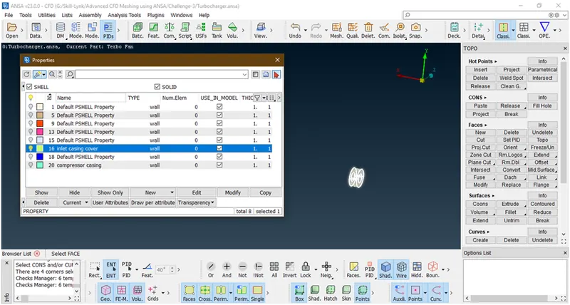
- Let assign ‘turbo casing’
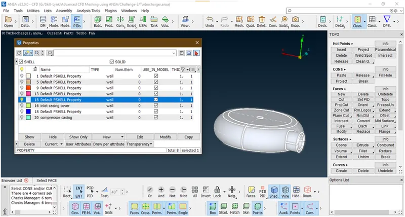
This is turbo casing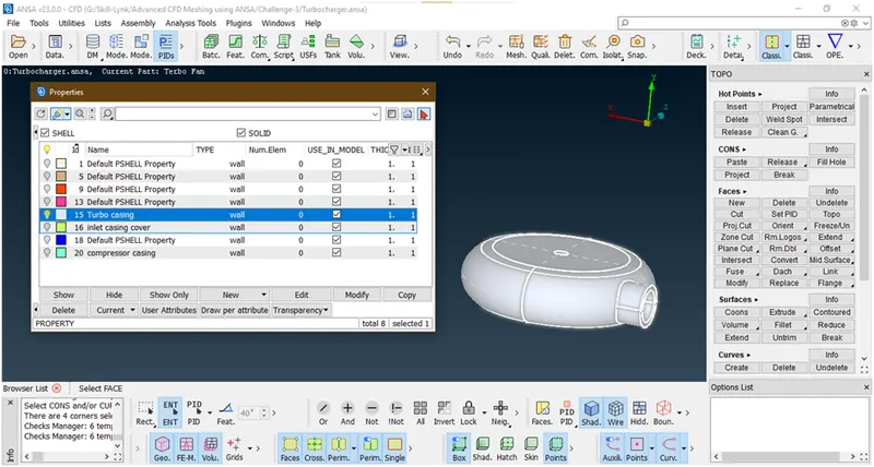
• Let assign ’impeller’
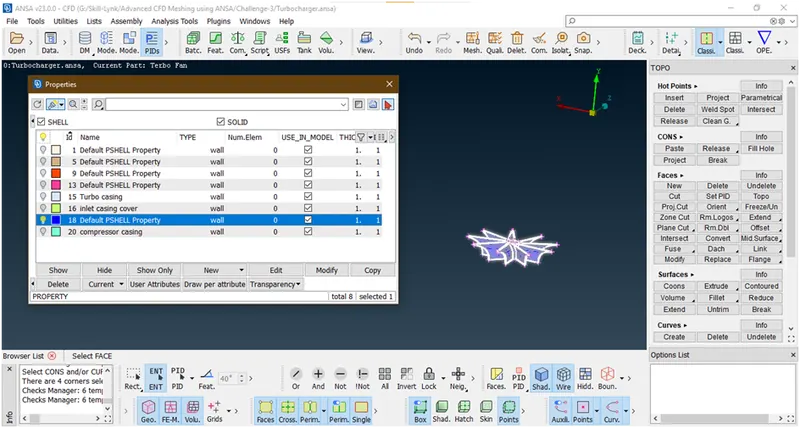
This is impeller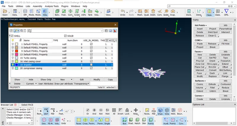
- Lets assign ‘Blade stage-1’
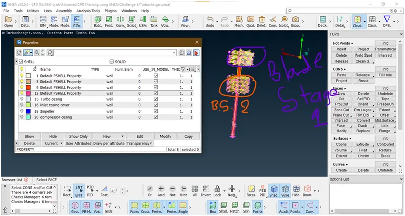 Let assign
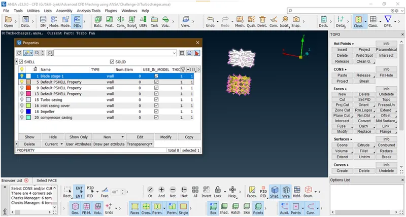
- Let assign ‘Blade-stage-2’
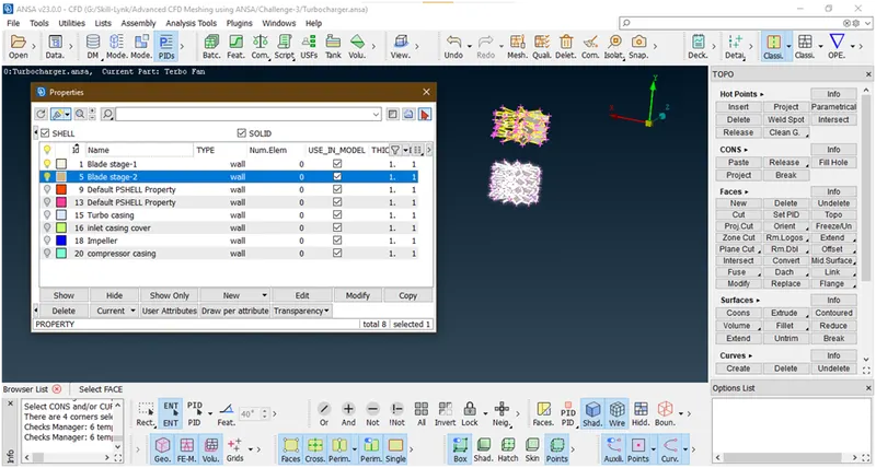
- Let assign ‘rotor shaft’
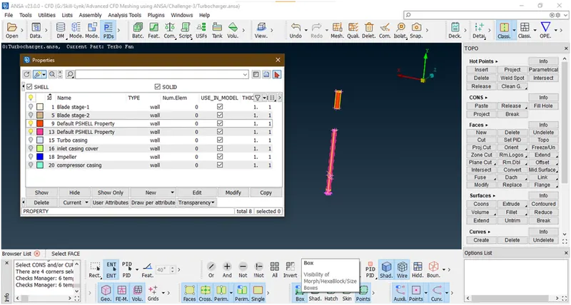
Lets create a new pid . Goto new in pid manager
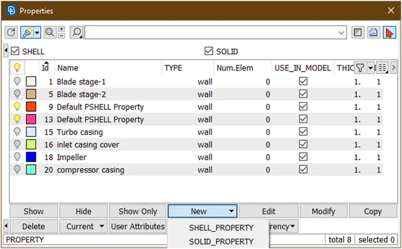
Select shell property, a new popup opens
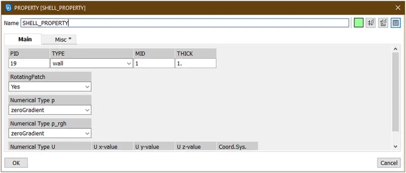
Rename as rotor shaft. Click ok .it will create a new pid.
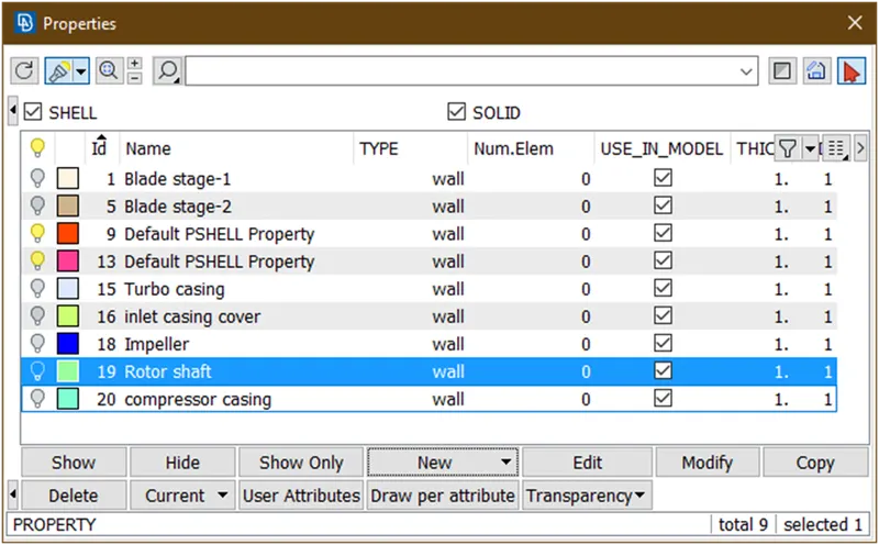
Now right click on this and goto apply
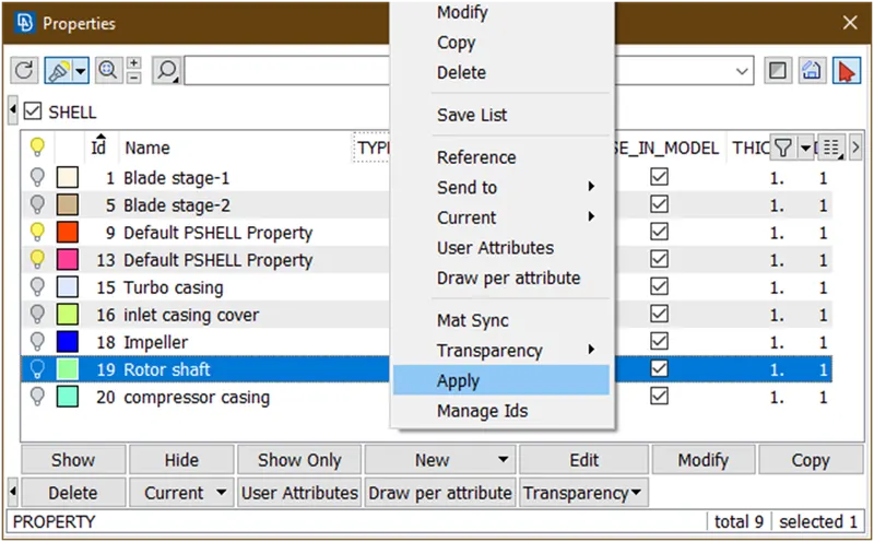
Now box select the faces
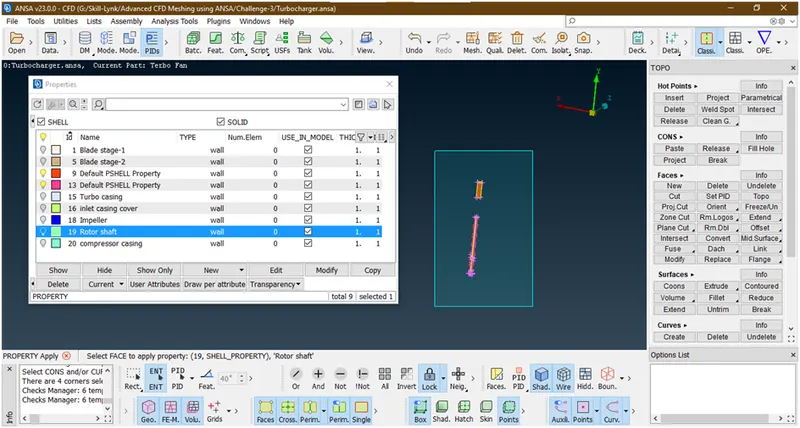
Its selected.Hit middle click.
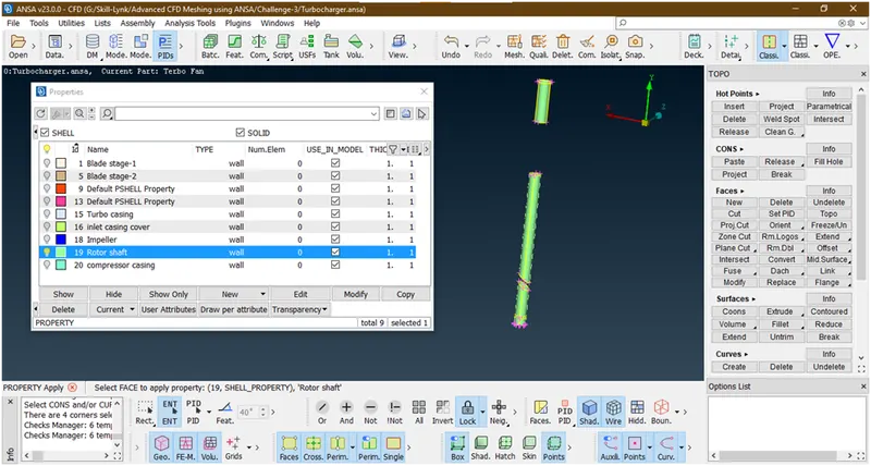
Now it has been assign. goto compress for deleting unwanted files from pid manager

New popup opens
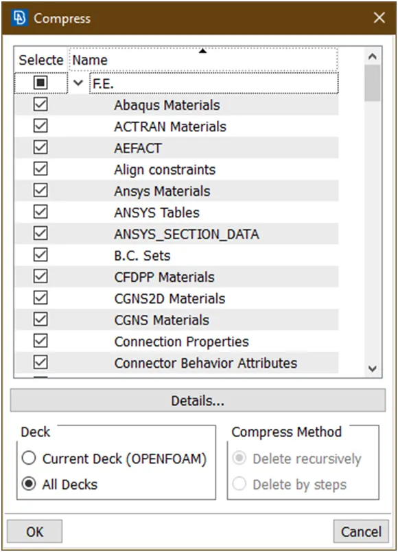
Click on ok.Now the files are deleted.
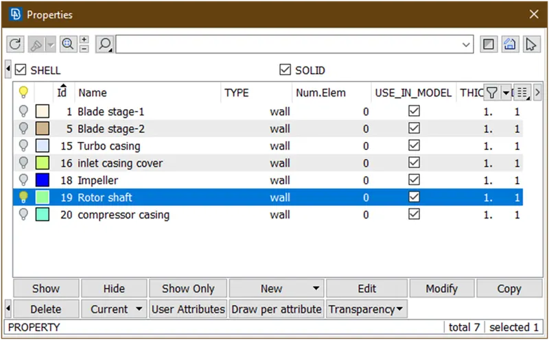
- Display all components by clicking on off-bulbs
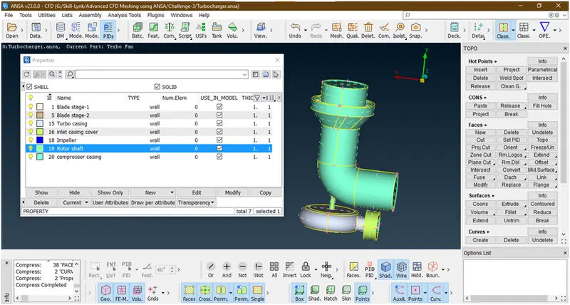
- Lets delete extra hot points.
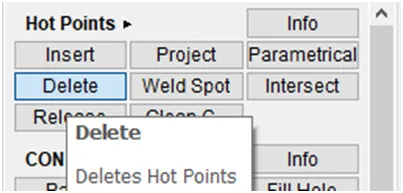
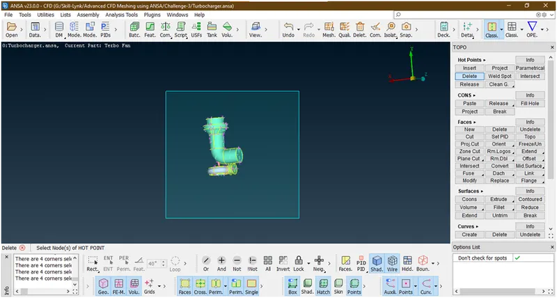
Now its deleted if present.
- Lets hit topo
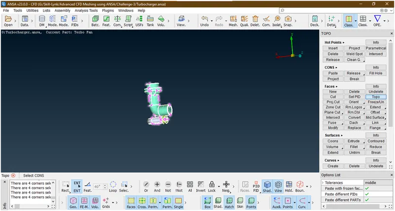
Hit middle click.Click esc.
- Lets again check for any errors
Now, we have clear all intersection errors. Lets see geometry errors
These are the triple cons and these surfaces are required. so we are ignoring this.
With this we are concluding all geometry cleanup.Let go for surface meshing.
3. Surface meshing of a turbocharger :
- Lets goto the classic mesh
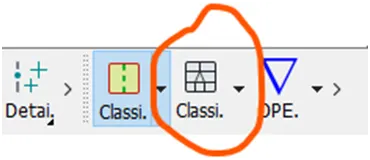
- Meshing interface looks like
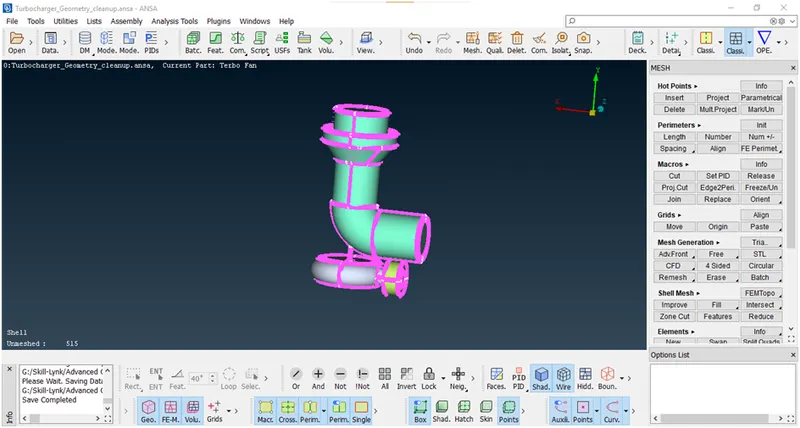
- In the question the target length is given as
- Blade stage-1 = 1 mm
- Blade stage-2 = 1 mm
- Impeller = 2 mm
- Shaft rotor = 1 mm
- Turbo casing = 5 mm
- Compressor casing = 5 mm
- Inlet casing cover = 5 mm
- Lets mesh Compressor casing
- Goto pid manager
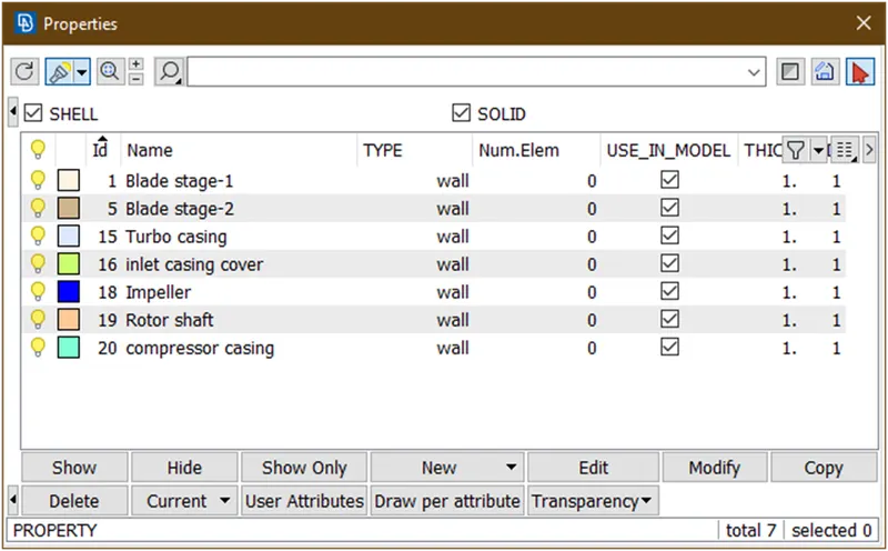
- Hide all other component by clicking on bulb to be off and show only compressor casing.
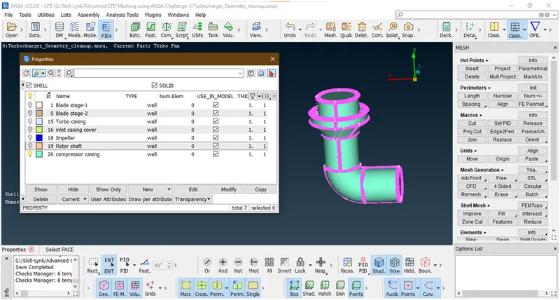
- Now close this pid manager
- Now here,
Target length=5mm.
- Now goto mesh parameters

A new popup opens
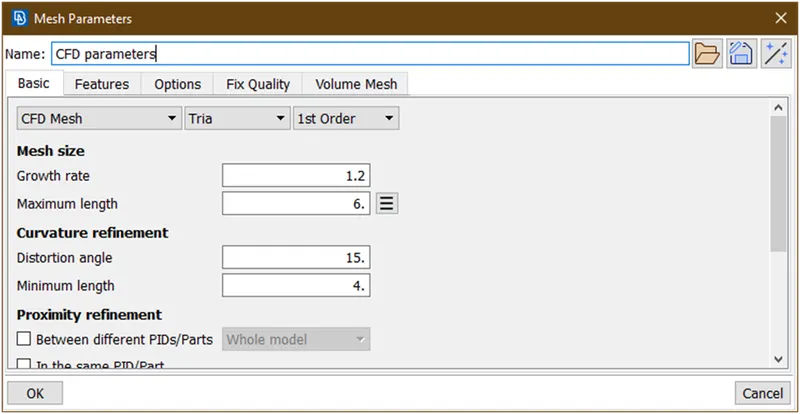
Now give, minimum length=4mm
Maximum length=6mm.
Then click on ok.
- Goto perimeter->spacing->auto cfd
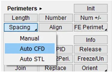
Then new popup opens
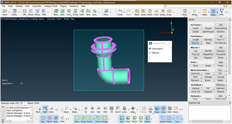
Click on perimeter and select component as shown above.hit the middle click. Again a new popup opens
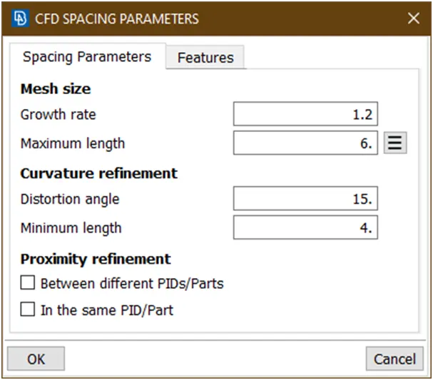
Click on ok. Then goto macros and select body
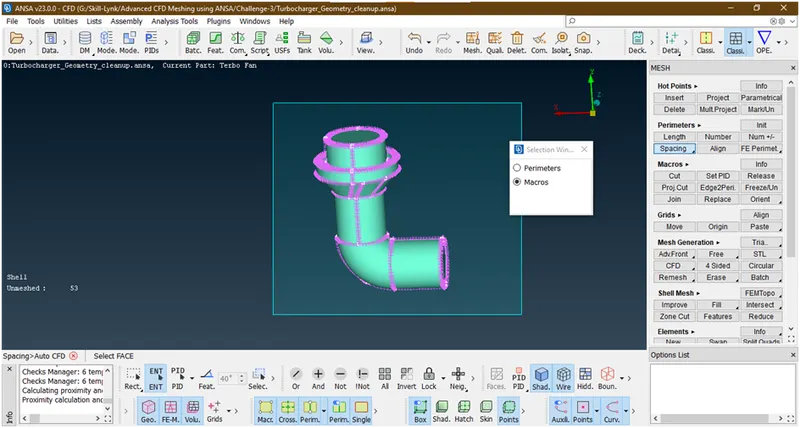
click middle click a popup open
Click on ok.
Press esc.
- Goto mesh generation->cfd meshing->visible
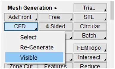
Wait for meshing to be done.
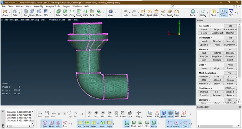
Now its done.
- Let we will freeze this mesh.
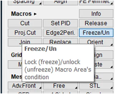
Now box select the faces by using left click of mouse.
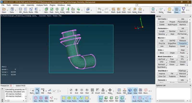
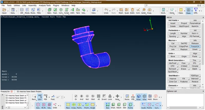
Now it has been frozen.
- Lets go for Turbo casing
- Goto pid manager
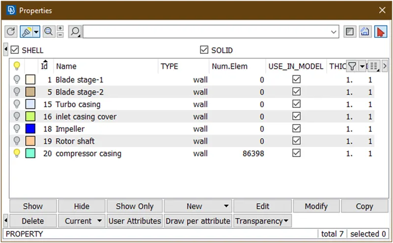
Turn on turbo casing and turn off compressor casing
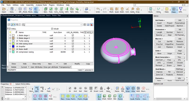
Close this tab.
- Here the target length=5mm so goto mesh parameter
New popup opens
Here also minimum length=4
Maximum length=6
Click on ok.
- Goto perimeter->length
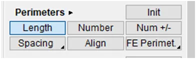
New tab opens , select perimeter and select component as shown below
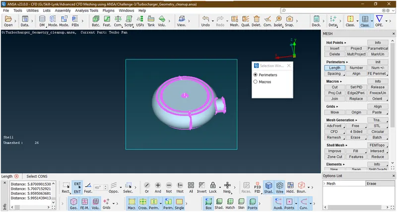
Hit middle click,new popup opens
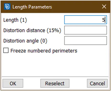
Give length=5 and click on ok.
Select macros and body
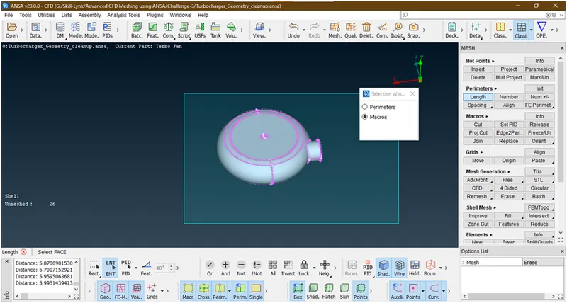
Hit middle click , new popup opens
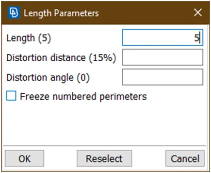
Give length=5
Click on ok.
Press esc.
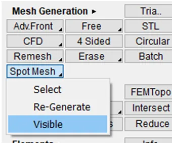
- Goto mesh generation-> spot mesh->visible,Wait until mesh done.
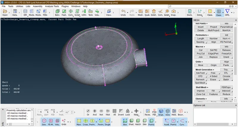
Now its done.
- Let freeze these mesh by selecting the faces
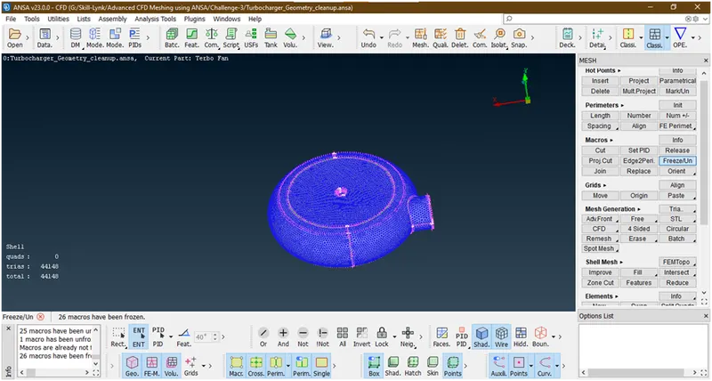
Now it has been froze.
Click esc.
- Now we are going forward for inlet casing cover
- Goto pid manager
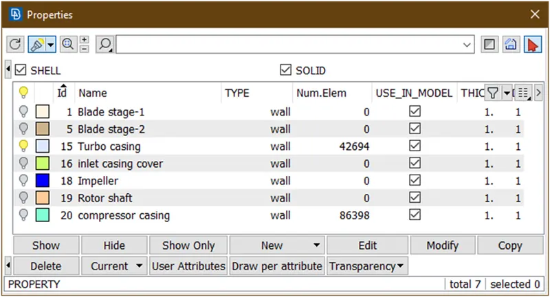
- Turn on inlet casing cover and turn off turbo casing.
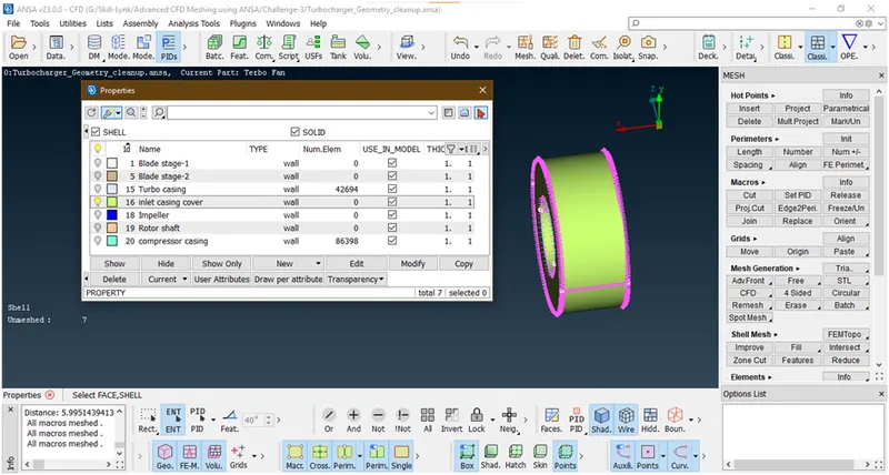
- Here the target length=5 given
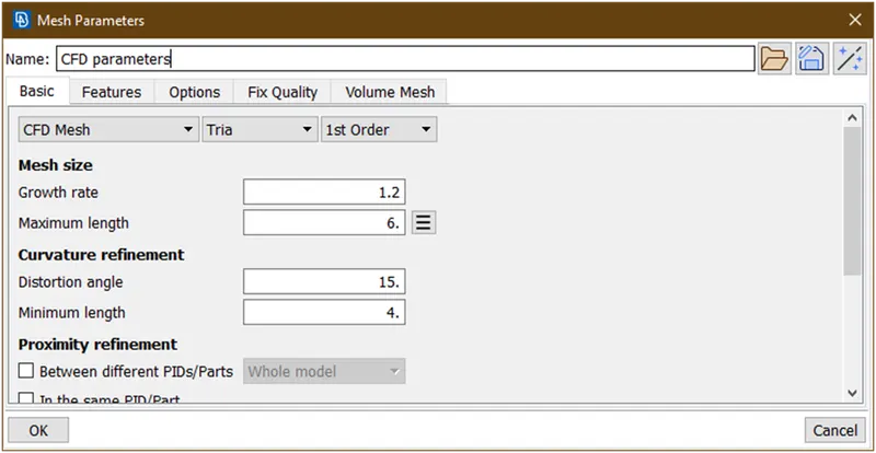
- Goto mesh parameter and give
Minimum length=4
Maximum length=6
- Goto perimeter -> length.Select perimeter and select body and hit the middle click a new popup opens
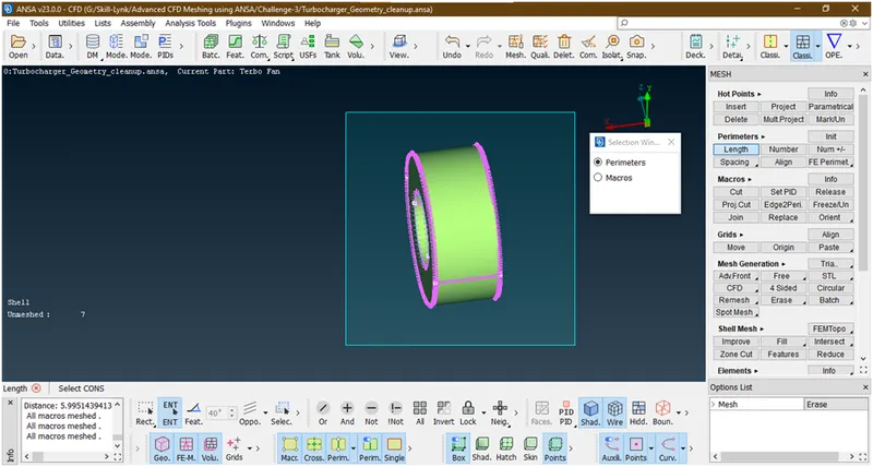
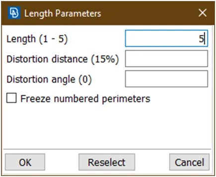
Put length =5 and Click ok.
Then select macros and select component
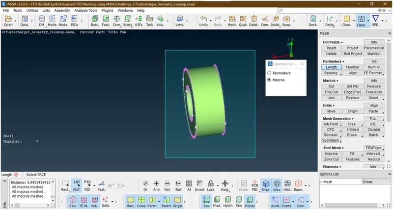
Hit the middle click. New popup opens
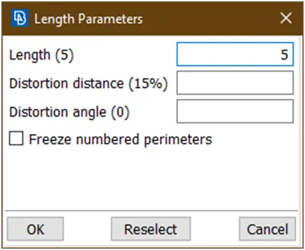
Put length=5 then click ok.
- Goto mesh generation->spot mesh->visible and Wait until mesh to be done
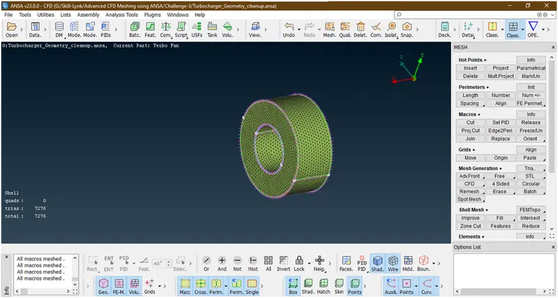
Now its done.
- Let freeze this mesh by Selecting the faces
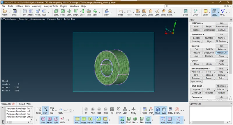
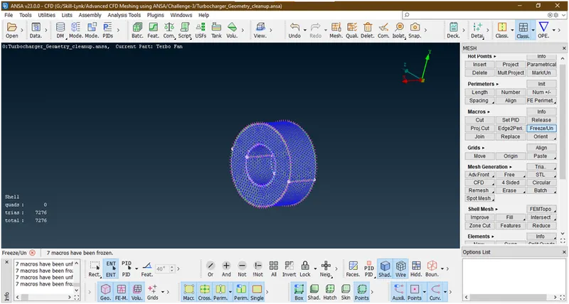
Now its done.
- Now we are going to mesh Impeller
- Goto pid manager and turn on impeller by turn off inlet casing cover.
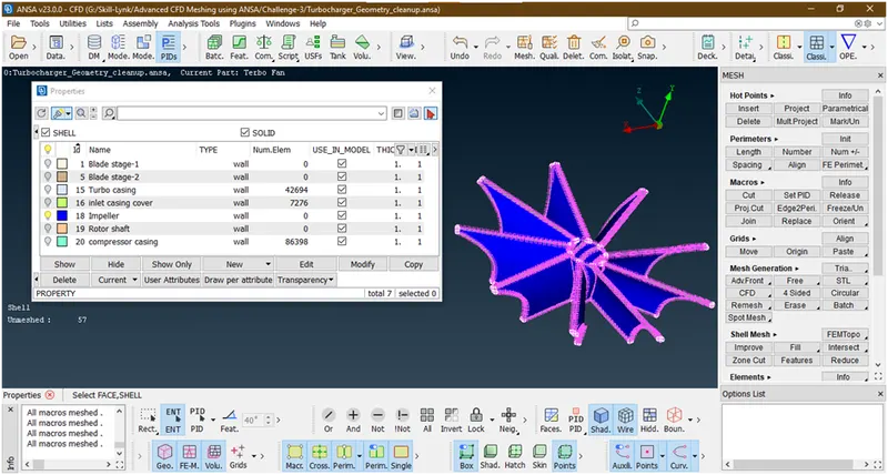
Here the target length=2.
- Goto mesh paramaeter
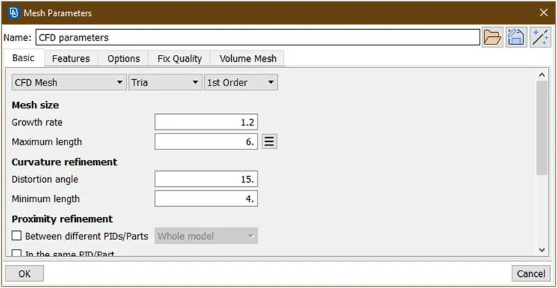
Give minimum length=1.5
Maximum length=2.5
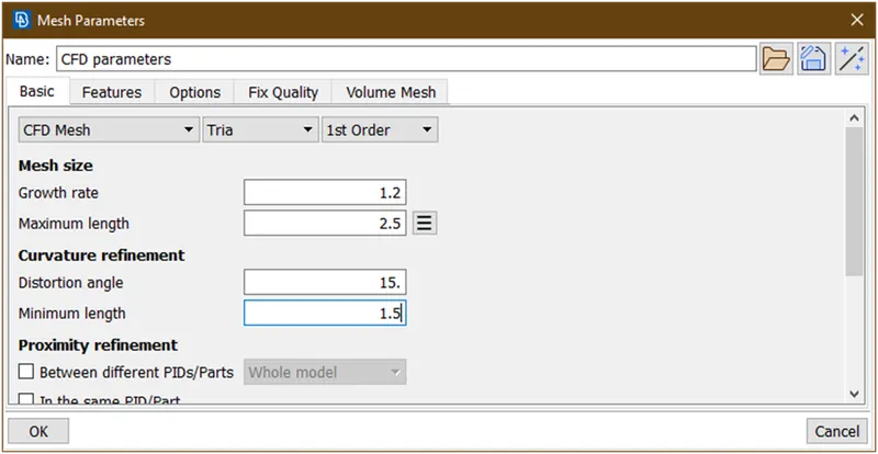
Click on ok.
- Goto perimeter->length, a new popup opens then select perimeter and box select faces
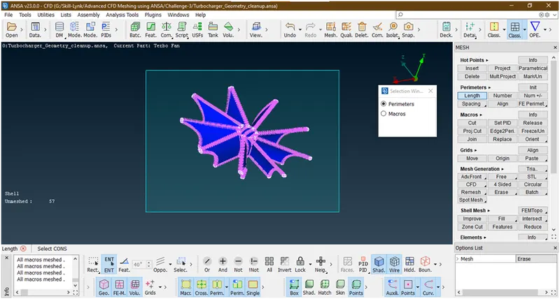
Hit middle click a popup opens
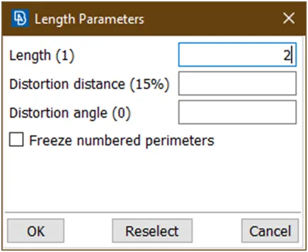
Give length=2 and click ok.
Select macros, box select all faces
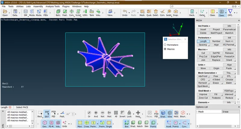
Hit middle click. A new popup opens
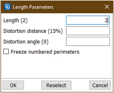
Give length=2 and click ok.
- Goto mesh generation->spot meshing->visible and Wait until mesh to be done.
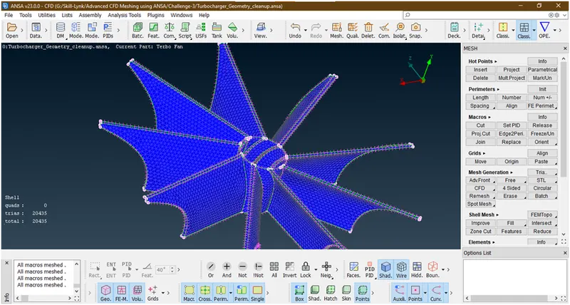
- let freeze the mesh by selecting the faces
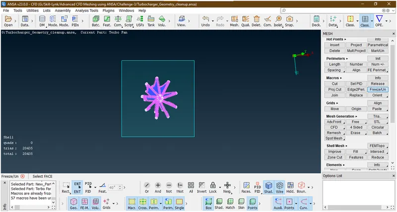
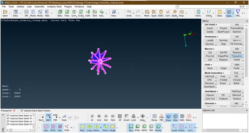
Now its fozen.
- Lets go for blade stage-1,2 and rotor shaft together because for all target length=1mm.
- Goto pid manager and turn on these component by turning off other components.
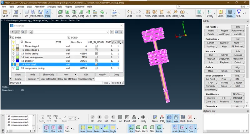
- Goto mesh parameter
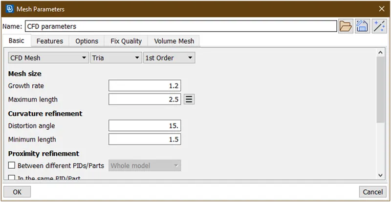
Give maximum length-1.5
And minimum length=0.5
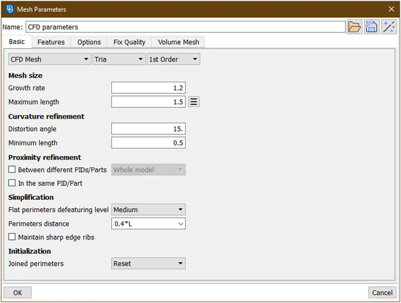
Click on ok.
- Goto perimeter->length and Select perimeter and box selection of all visible component
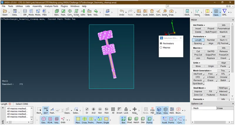
Hit middle click.new popup opens
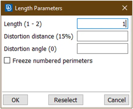
Give length=1
Click on ok.Select macros and box selection of all visible component
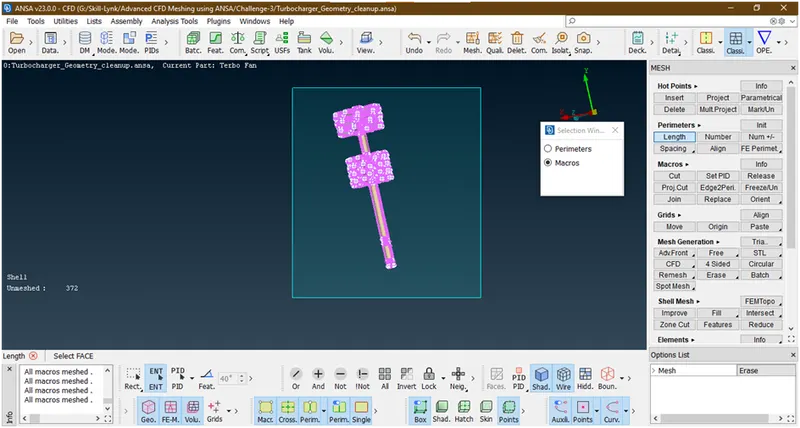
Hit middle click.
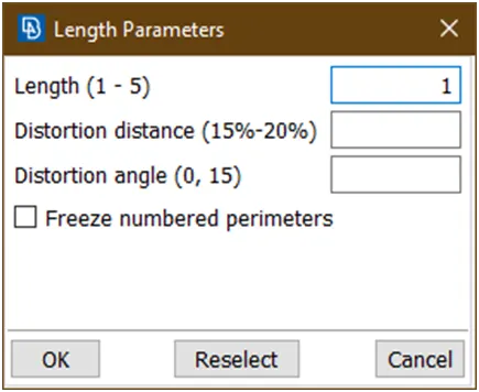
Give length=1 and click on ok.
- Goto mesh generation->spot meshing->visible and Wait until mesh to be generate
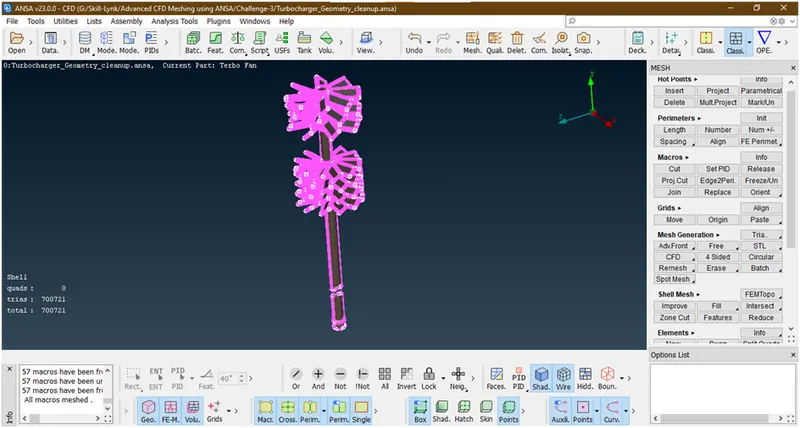
Now its done.
- Let freeze it by selecting the faces
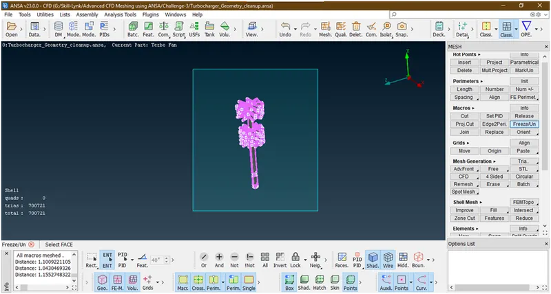
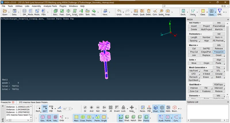
Now it has been frozen.
- Lets cross check each part so that any part left as unmeshed or not.
- Lets do all
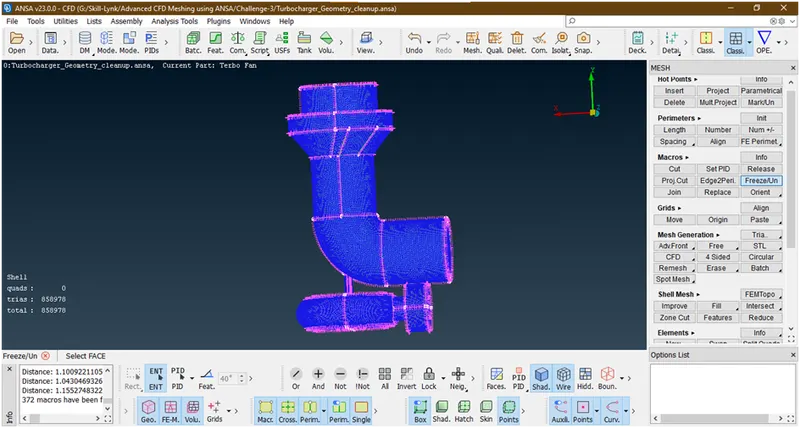
Now from here we have seen that there is no part of geometry is remain as unmeshed.
- For further operations unfreeze this macros.
Goto freeze/unfreeze
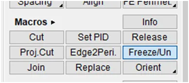
Now do box selction of all visible faces by using right key of mouse
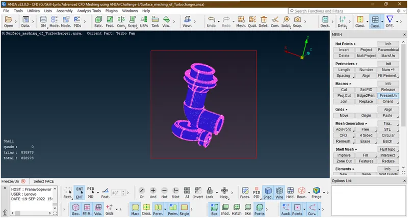
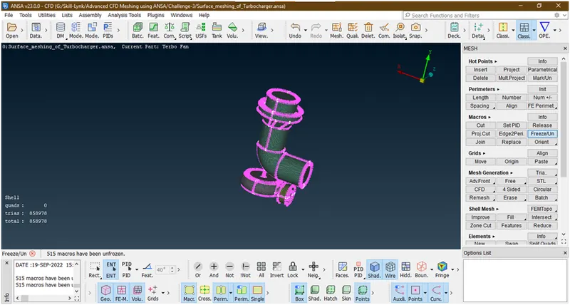
- Let view the cut section view.
- Goto the cut plane
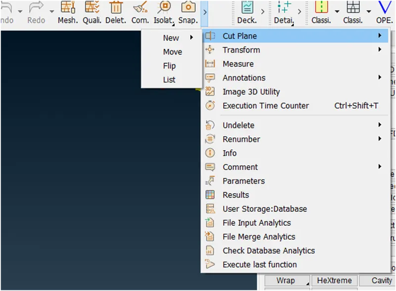
- Goto new->xy plane
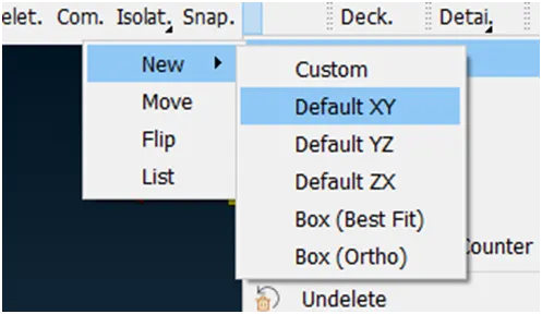
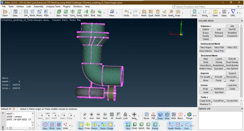
Now its asking for node/point. for that select any point/node on geometry
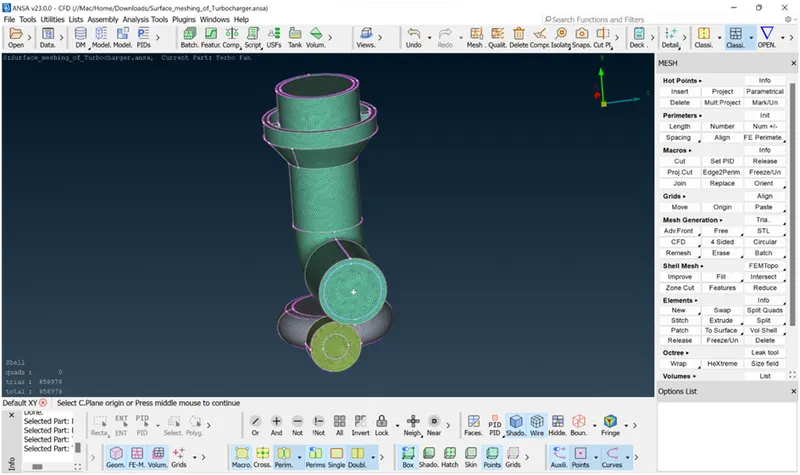
now a new popup opens.
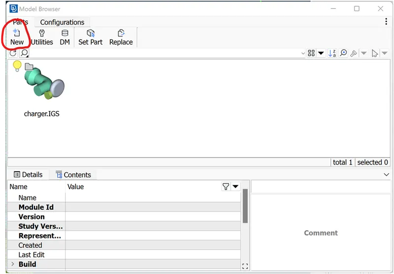
then select new-> part
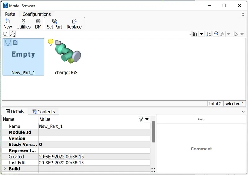
now double click on new part which highlighted ,a new popup opens and showing the section view
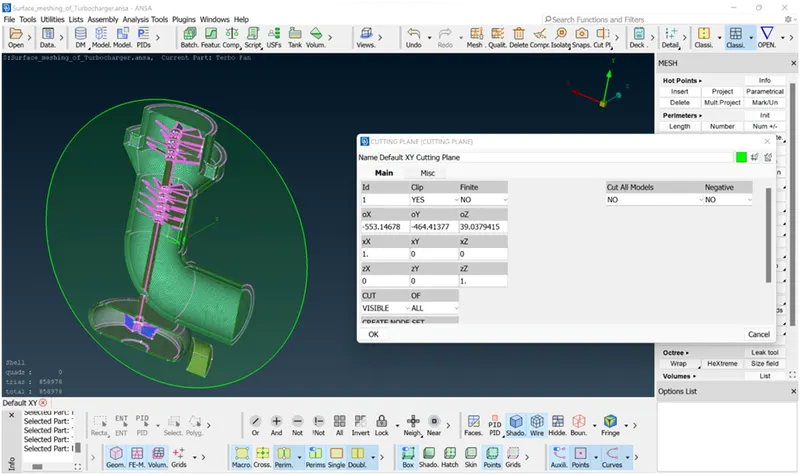
now this is the final cut view of surface meshing.
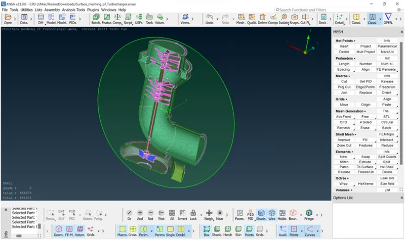
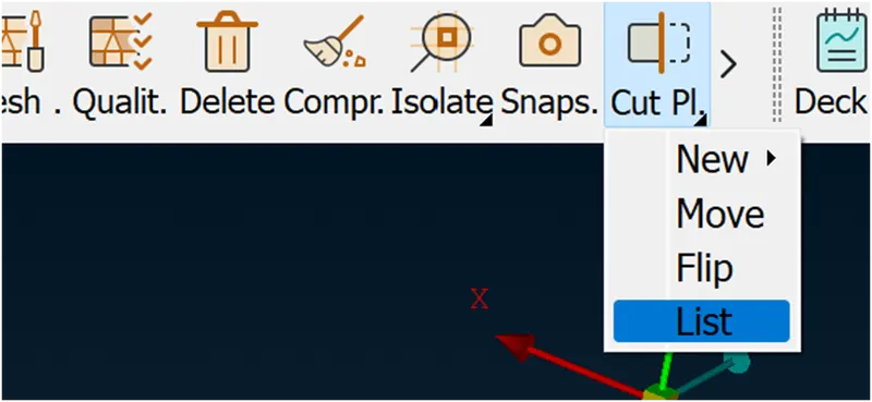
now hide this cut view. For that goto cut plane->list
new popup opens
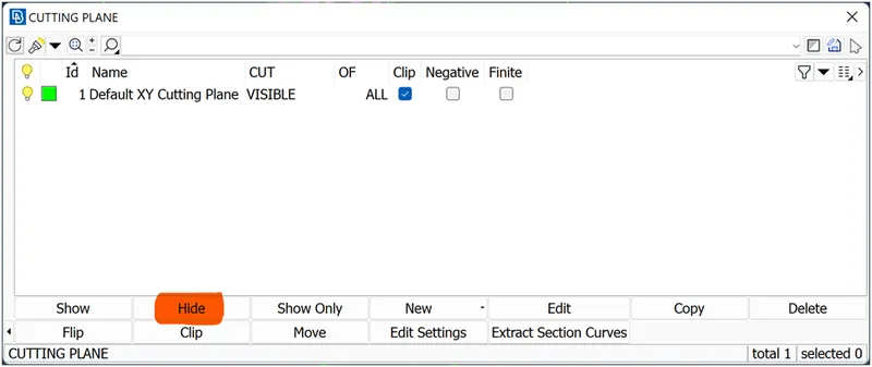
now first select this plane from list and then click on hide.
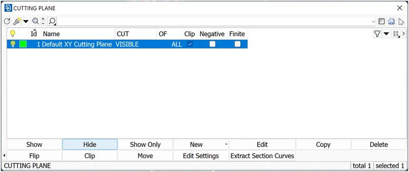
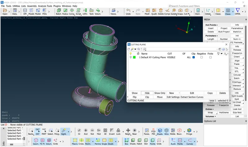
Now it has been hidden then closes this tab. So we have successfully created surface mesh .Now we are going for volume meshing.
4. Volume meshing :
- Goto volume mesh
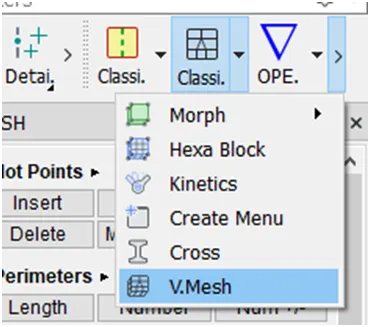
Volume mesh interface look as
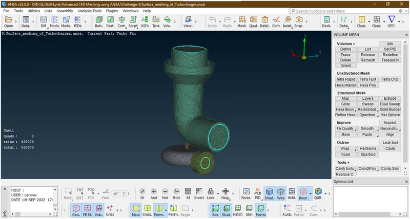
- Goto volumes-> defines
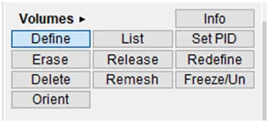
Now a popup opens
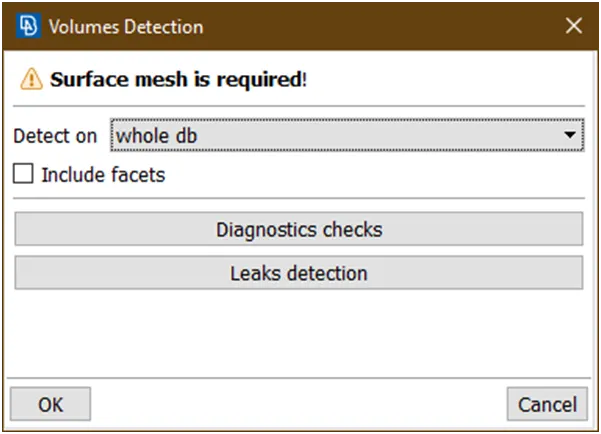
Click on ok.Again a new popup opens
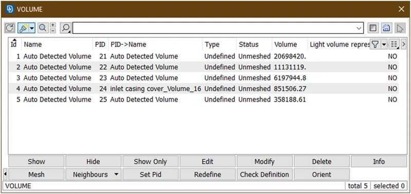
- These are the 5-autodetect volumes in geometry.
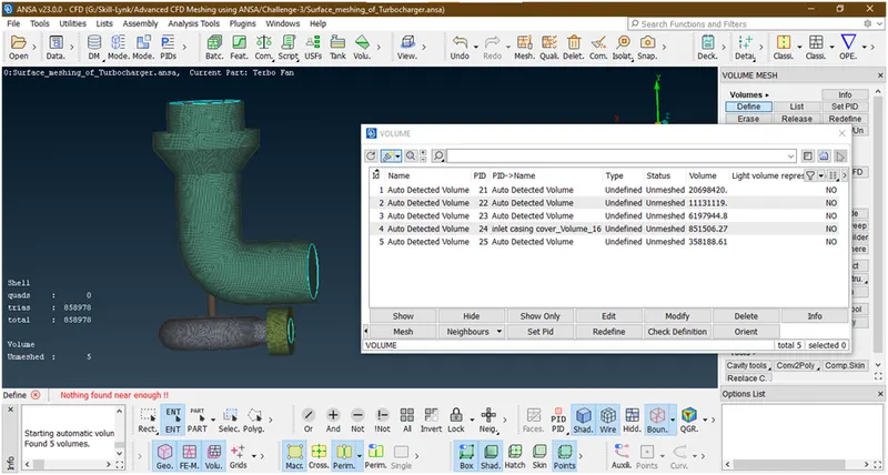
Let check the volumes which are they and delete the volumes which are not required. Now here we are doing internal flow analysis in turbocharger so delete external volumes.
- Lets go for 1st volume
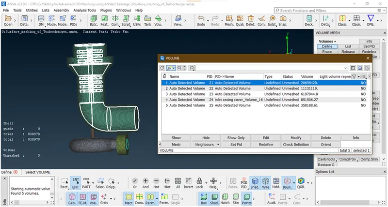
This volume is showing in the internal part of compressor casing so we need this.so keep this.
- Lets go for 2nd volume
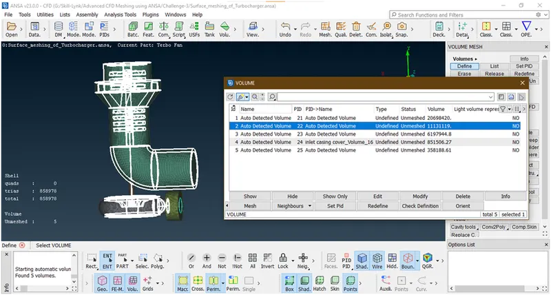
This shows the external volume of geometry. so don’t want this so delete this.
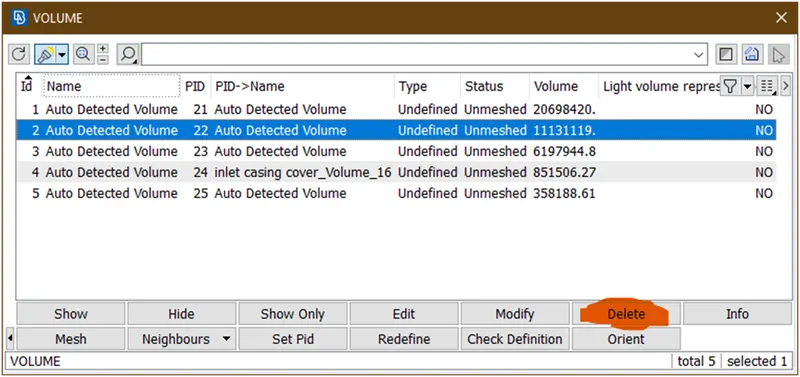
Click on this delete tab. A new popup opens
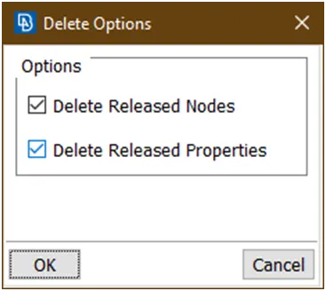
Click on ok.
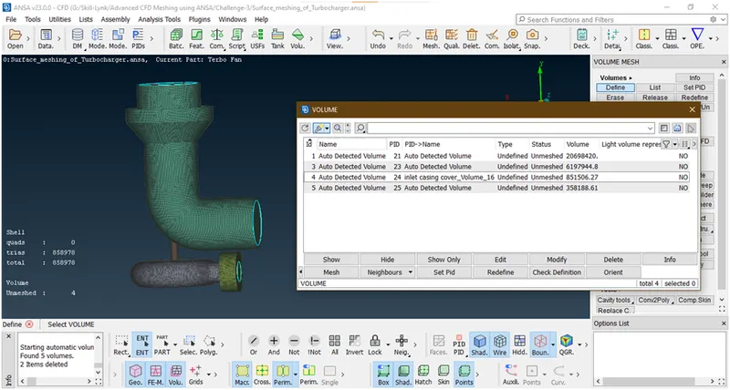
Now it has been deleted.
- Lets go for next volume
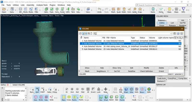
This is internal volume of turbocasing.so we want this.so keep it.
- Let go for next volume
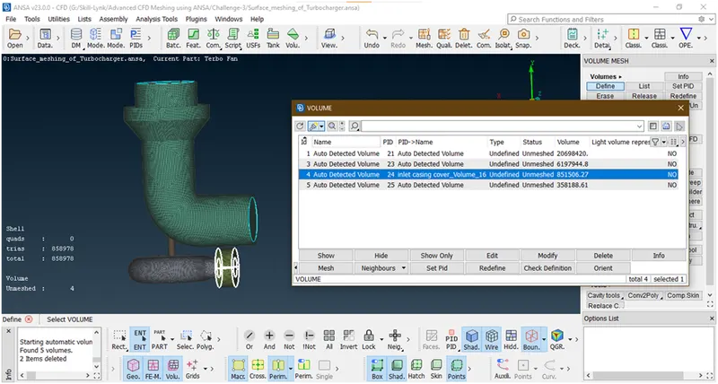
Now this is showing the external volume of a inlet valve casing and don’t want this. so we are going to delete this by using same option as shown above.
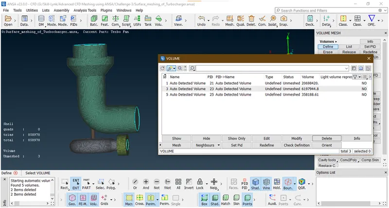
Now it has been deleted.
- Now lets go for next volume
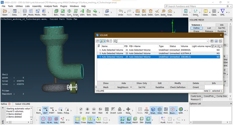
Now this is again internal volume.so we are keeping this.
- Now we are going for volume meshing
- Lets do 1st volume to be mesh
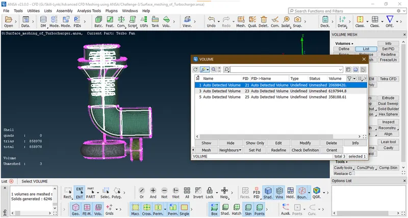
Now we are going for this Double click on 1st volume

A new popup opens
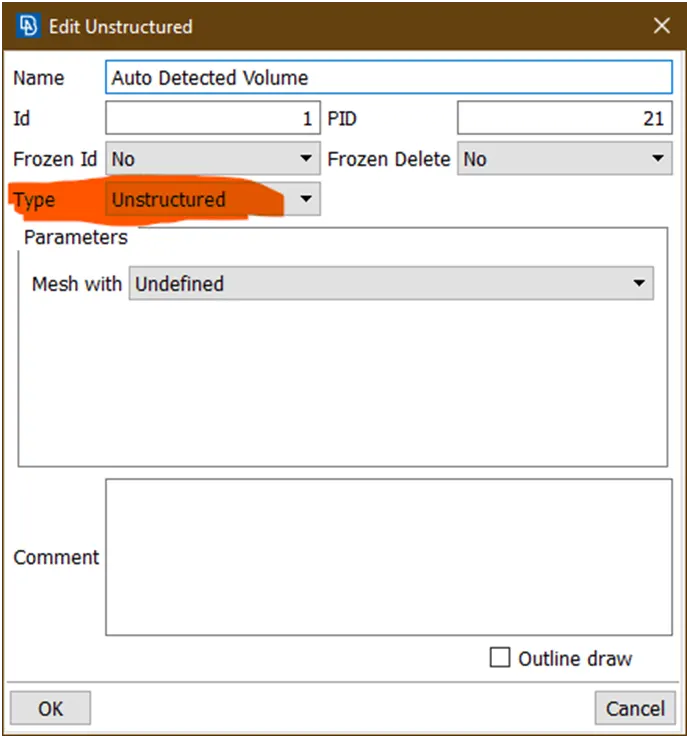
Select type=unstructured.
Select mesh with= tetra rapid as shown below.
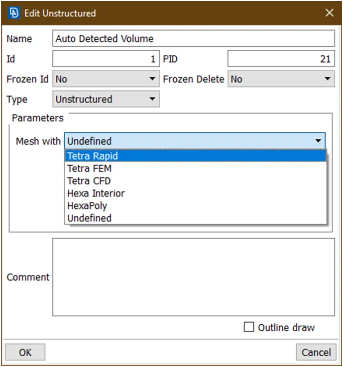
Click on this tetra rapid
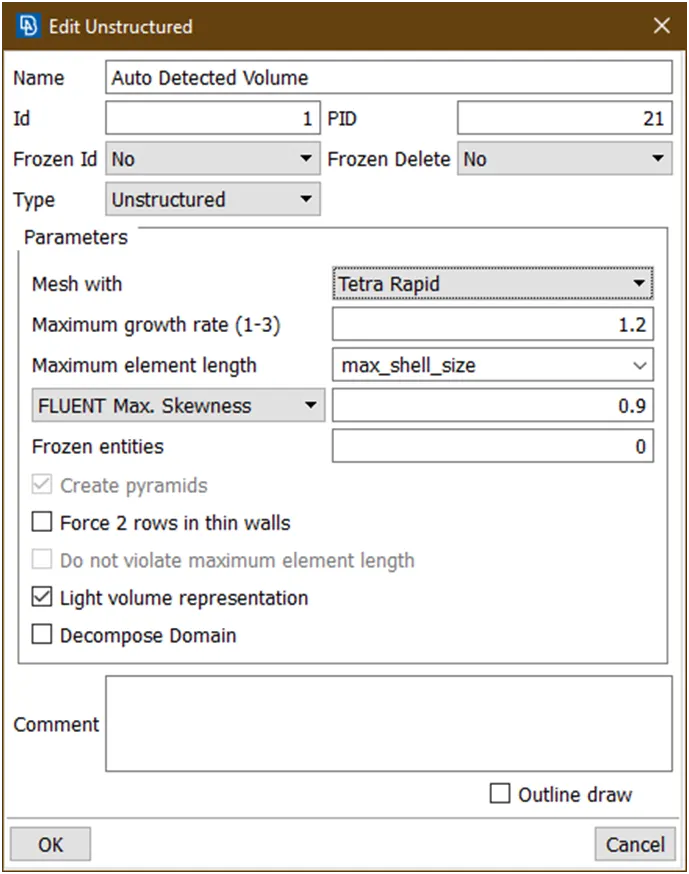
Click on ok .Now click on mesh
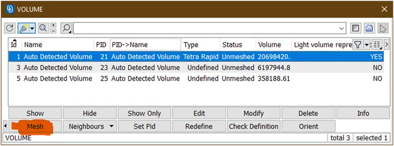
And wait until mesh to be done.
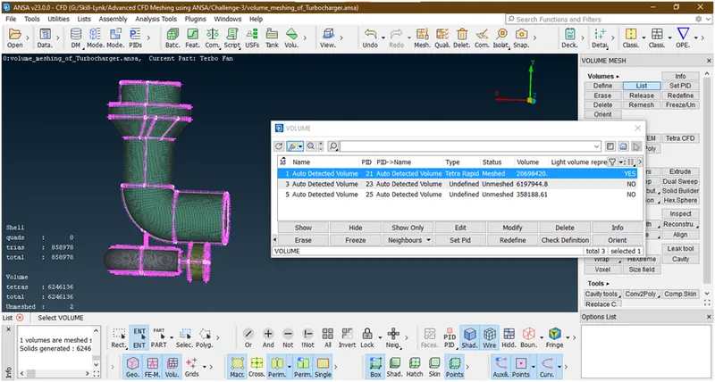
Now the volume mesh done for this as shown above.
- Let go for next volume
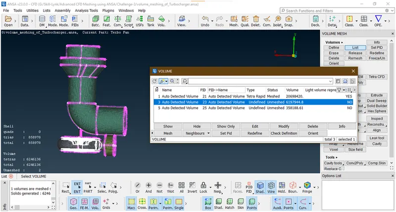
Follow the same procedure for volume meshing as given above
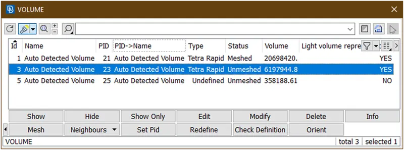
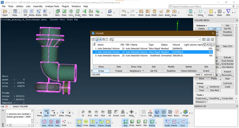
Now its done.
- Now we are going for next volume
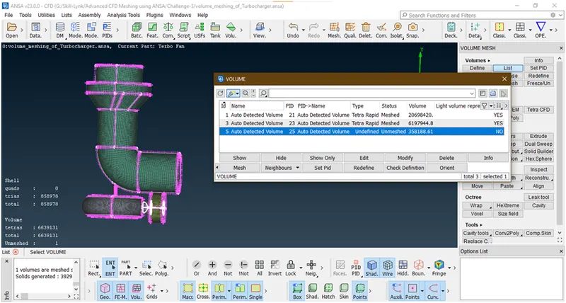
Now for meshing follow same method as mentioned earlier.
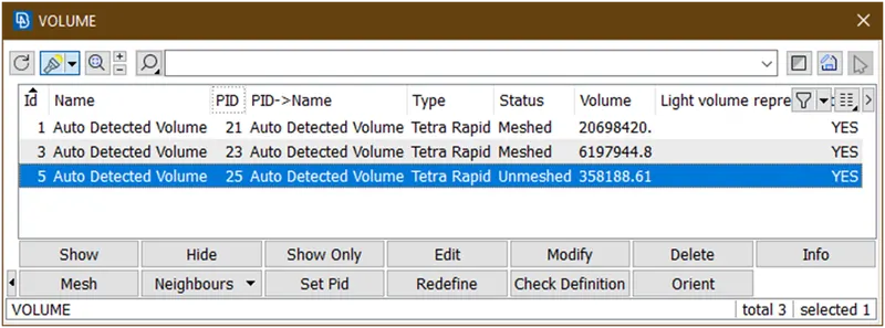
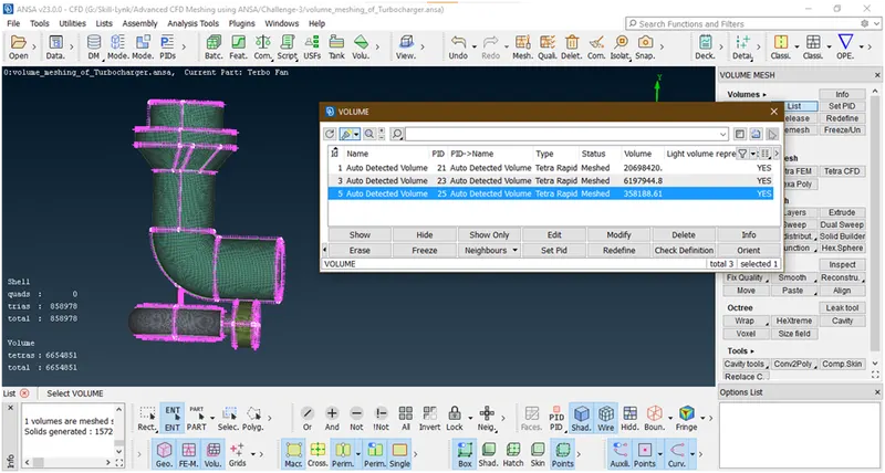
Now its done.
Now the volume meshing also done.
- Lets view a cut plane view.
- Goto the cut plane
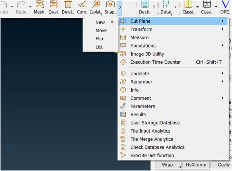
- Goto new->xy plane
- Then select the point anywhere
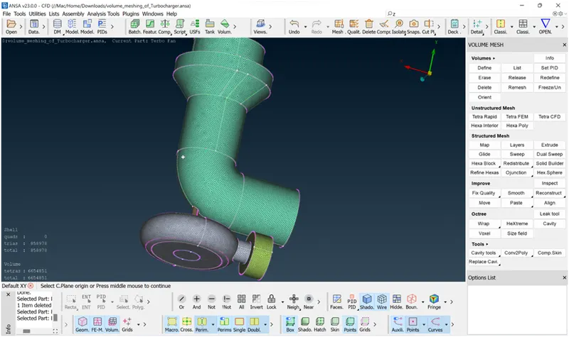
now a new popup open
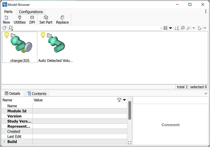
goto new->part
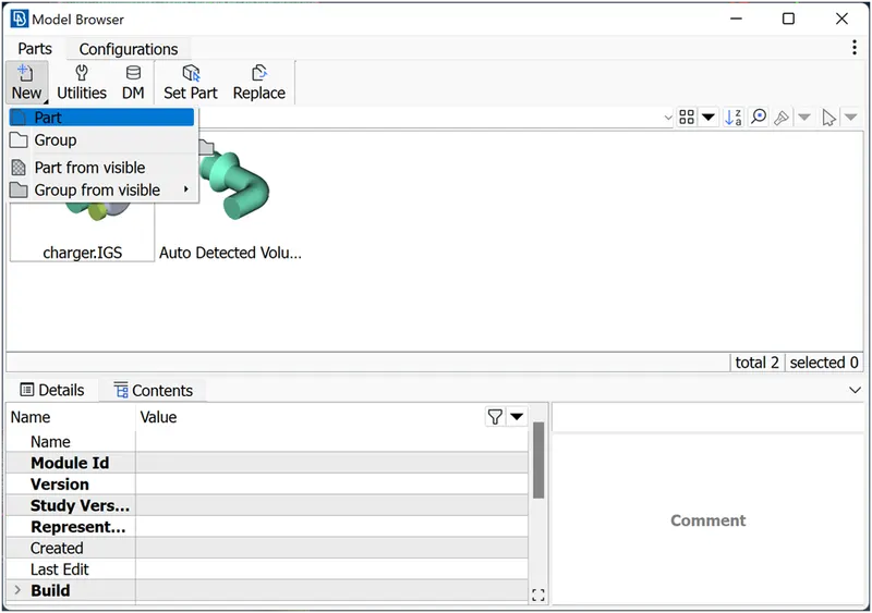
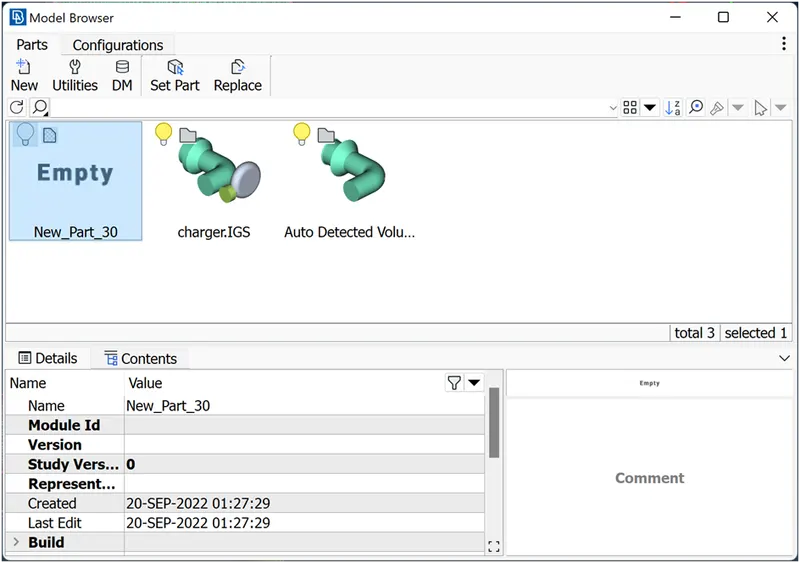
- double click on this new part a new popup opens and shows cut plane section
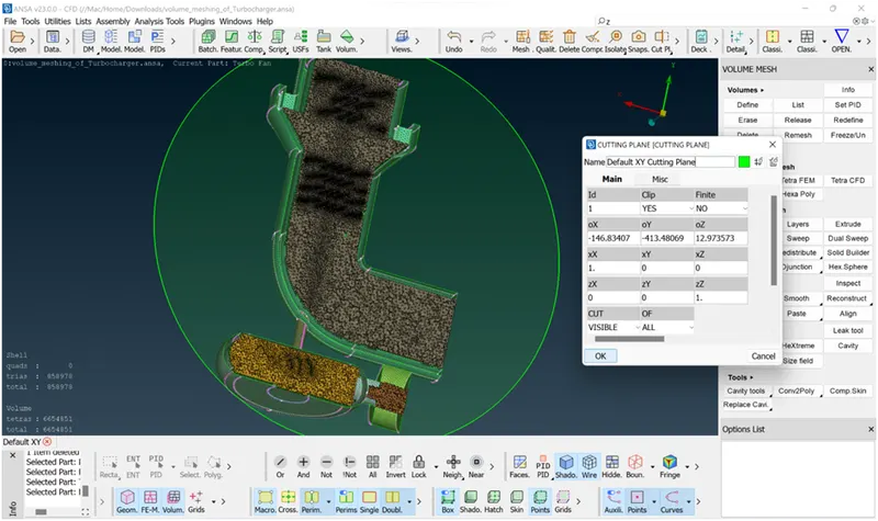
then click on ok.
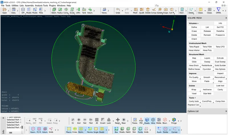
now it has been created. and the tetra rapid volume mesh is shown.
- let hide the cut plane
- goto cut plane-> list
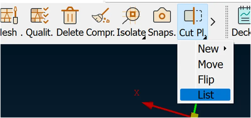
a popup opens
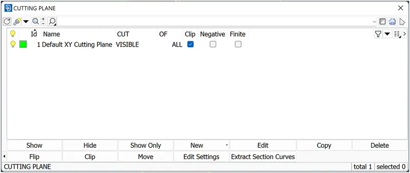
select plane and click on hide
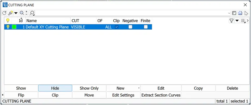
now it has been hidden
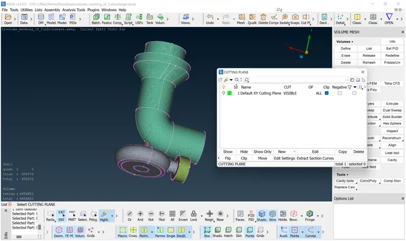
now close this tab/press esc.
Results :
- Surface meshing of a turbocharger
- Volume meshing of a turbocharger
Note:
- I have did mistake while putting pics in rotor shaft for meshing so I got some confusion that is I did any mistake so I have check in files for meshing and but it not found and while doing this the total number of mesh has changed and I have put recently work files.so please ignored the total number of elements.
- The geometry is correct.
Conclusion :
- I have learn how the volume meshing to be done in ansa.
- I have also learn how we can do surface meshing using various mesh generation techniques.
- I have learn how to use various tools for geometry cleanup.
Output files :
- Surface meshing of a turbocharger
https://drive.google.com/file/d/1RE3-Uljpcmfc8OFKcxILTRzvhtf1Qiyb/view?usp=sharing
- Volume meshing of a turbocharger
https://drive.google.com/file/d/1eJM-K5ktoFP7hXL3ysCjLG9fSqhmIm7U/view?usp=sharing