Week 2 Challenge : Surface meshing on a Pressure valve
CHALLENGE-2
Aim: Surface meshing on a Pressure valve.
Objective: For the given model, check for the geometrical errors and perform Topology cleanup accordingly. Set three different target lengths as three different cases and mesh the model.
- Target length = 1mm, 3 mm and 5 mm (i.e. 3 cases)
- Element type = Tria
Theory :
- Pressure valve is a type of valve which release the extra pressure which is created in the system such as boiler created due to temperature in the form of steam.
- Pressure valve is very important component boiler.
- This valve is also known as relief valve.
Procedure:
1. Importing geometry :
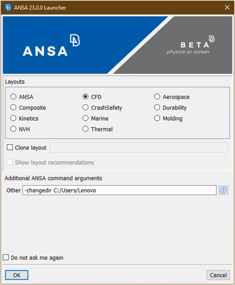
- Open the ansa software then the dialog box come as shown in below figure and For CFD applications it is recommended that ANSA is started in CFD mode, by selecting the corresponding option from the launcher window. This will allow the better setup of the software interface for CFD pre-processing.
- At ansa command argument write ‘-performance_mode 3’ for smooth running the software in regular laptops/pc because to run the this software we required high configuration but our pc’s are not build to run these softwares as shown in below figure
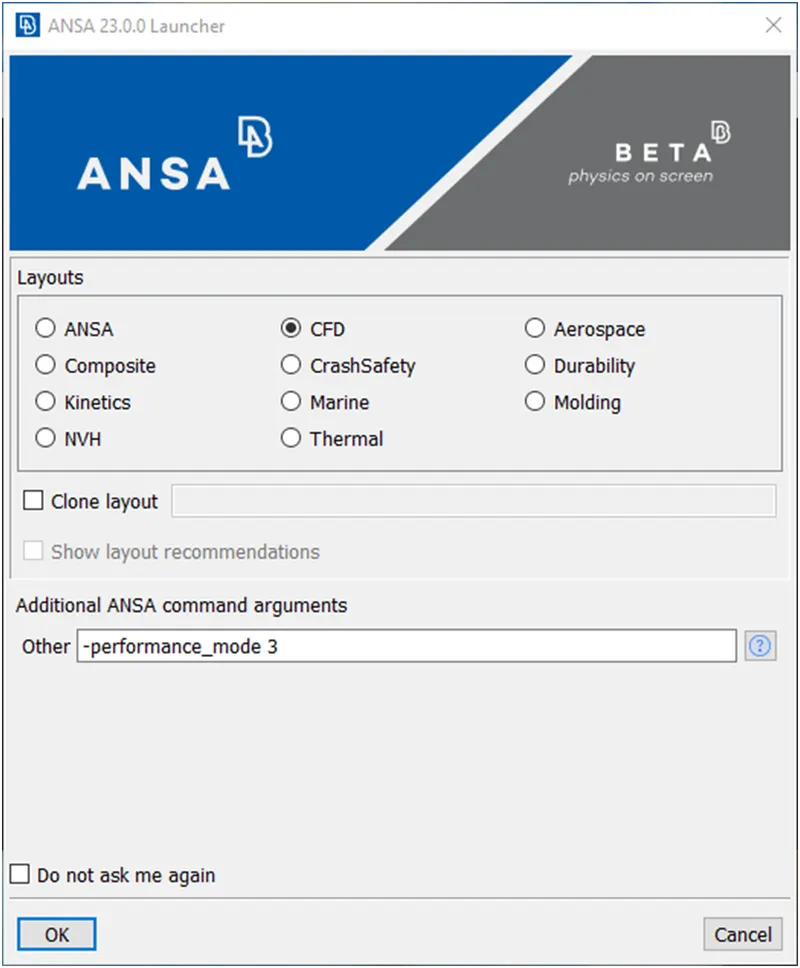
Then click on ok.
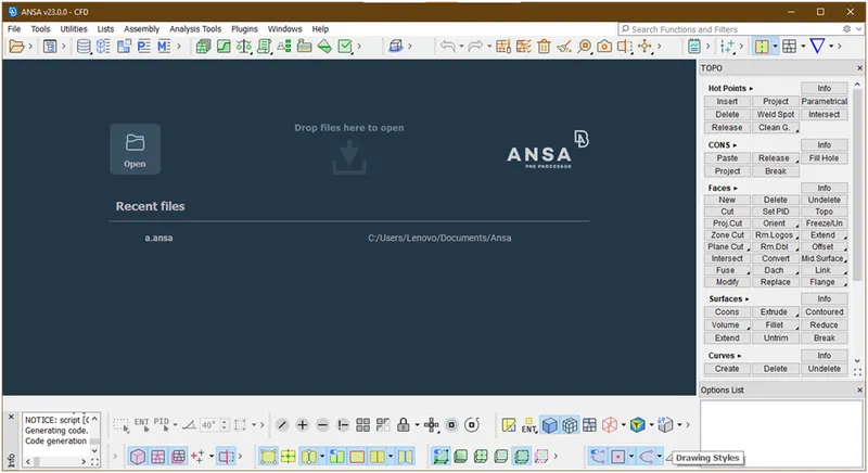
- Now the ansa user interface is open as shown in below figure.
- Now ,right click on bottom menu then the dialog box is open as shown in below and find show lables and click on radio button.
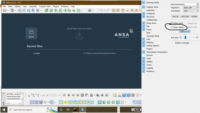
Now the lables will show as shown below figure.
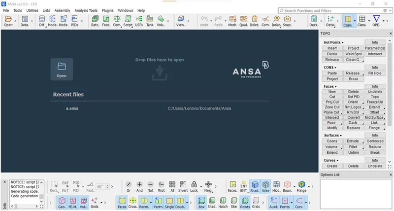
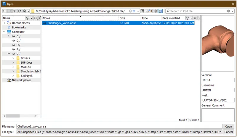
- Open the ansa file which is required here.
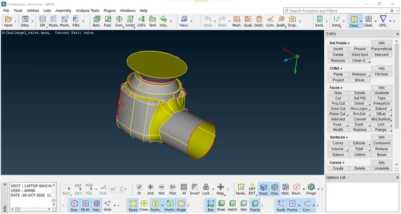
Here the geometry looks as shown in below figure.
2. Geometry cleanup:
- Firstly check for any geometrical errors in geometry by using check manager tool
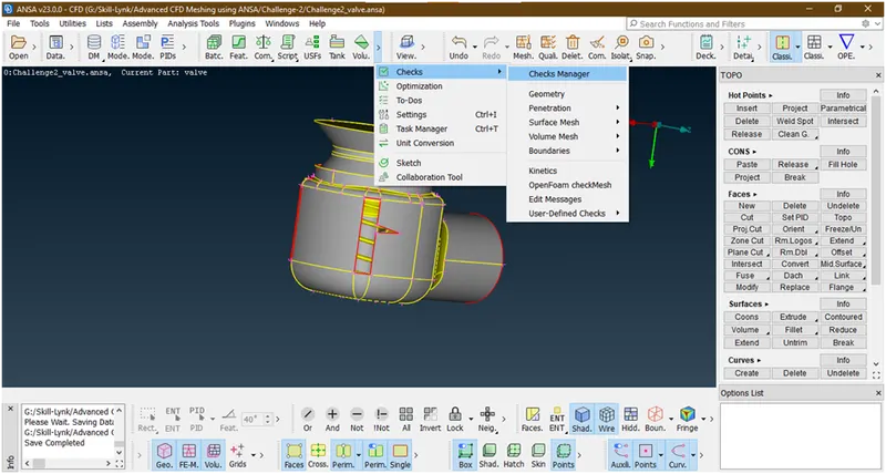
New popup is open
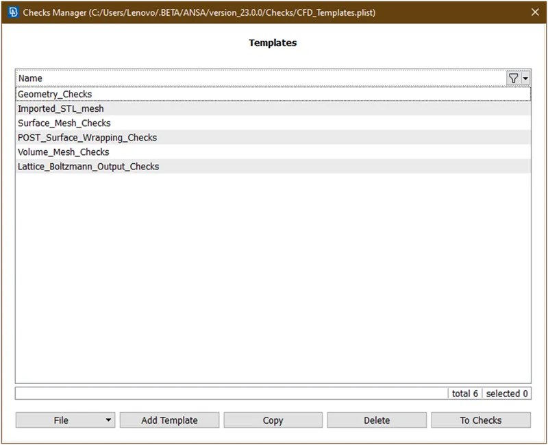
Double Click on geometry checks
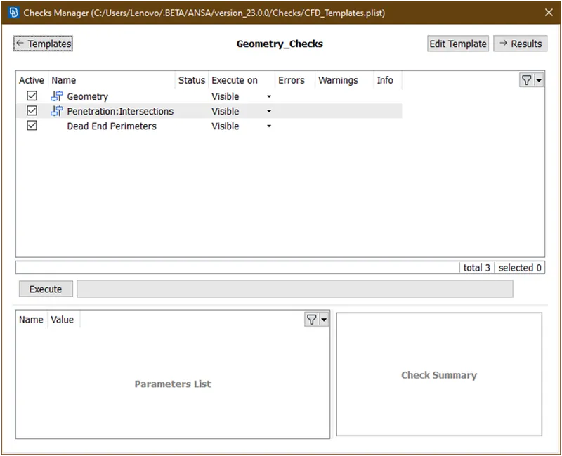
The above popup is open then click on execute.
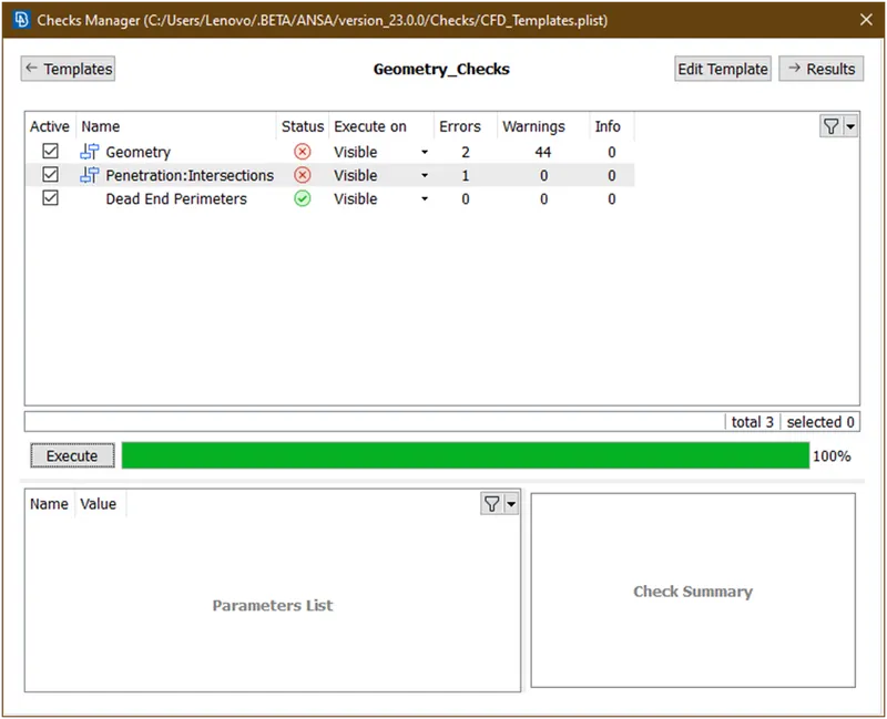
Now lets check for geometry checks which are they.
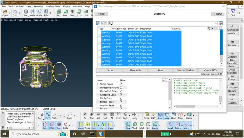
These are the geometry errors. Here the errors are showing are single cons it means there is missing surfaces so we have to create or delete surfaces which are required.
Now lets see for intersection errors which are for that click on back and again double click on intersection.
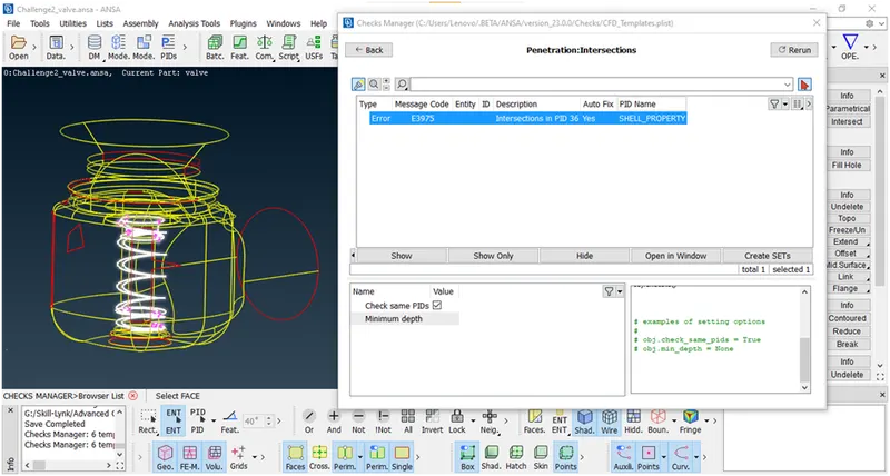
This is the intersection error. This is in wireframe mode . to switch from shadow mode to wireframe mode and vice versa click ‘control + shift ‘ together and hold.
Firstly lets clear geometrical errors.
- Lets apply topo tool under faces for autofix.
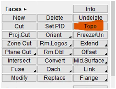
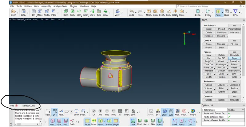
Now its asking for select cons.for that select total body by box selection as shown in figure
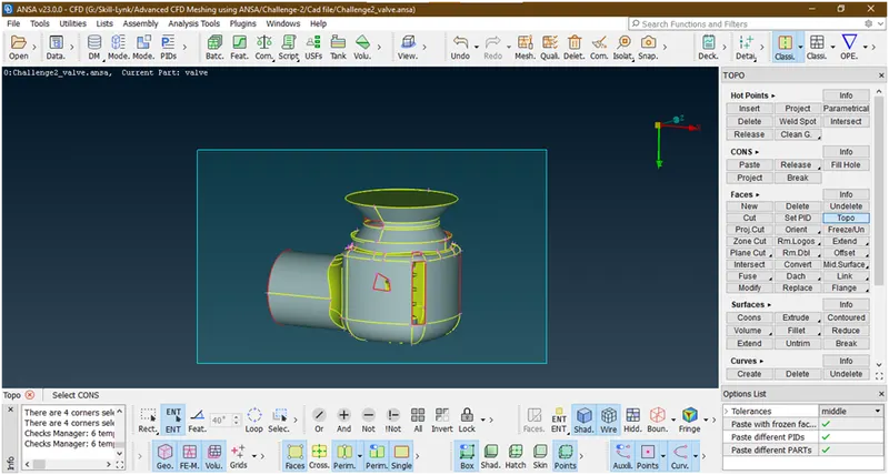
Now its selected as shown in figure below
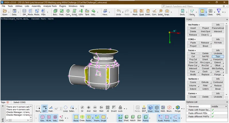
Now hit the middle click for execution .topo will apply then hit esc to stop operation.
Now this will automatically reduce the errors which are in there geometry which are possible.
- Lets fill the hole as shown in figure below by using ‘fill hole’ tool under cons.
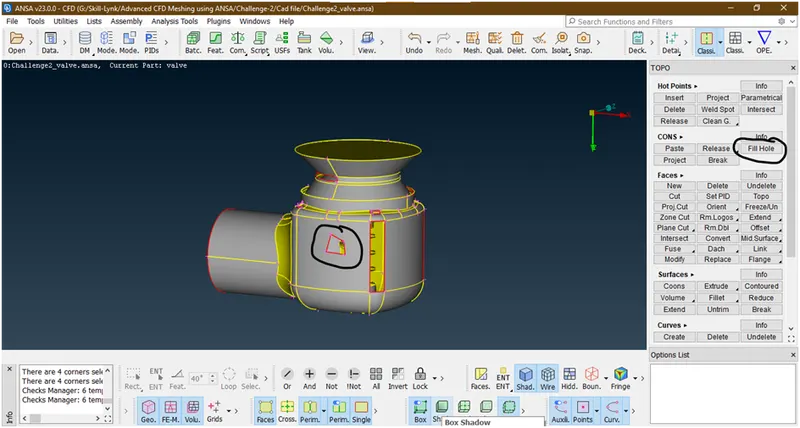
When you apply fill hole option a another popup shows as below
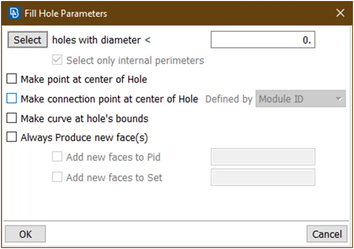
Now just select cons and hit ok as shown below.
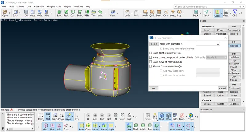
Now this error we have removed.
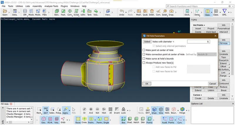
Now close this dialog box and go for to remove next error.
- Now lets clear this error
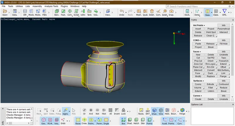
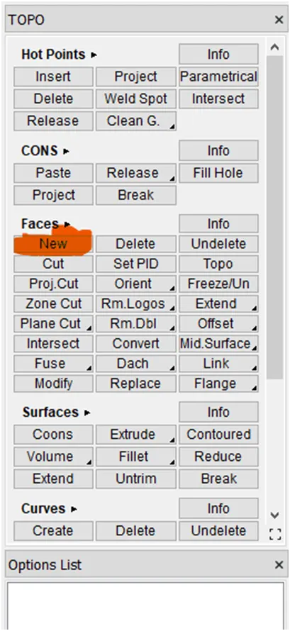
For clear this error I am using new surface tool under faces
The new popup screen open
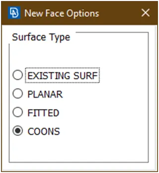
Now its asking for select cons,so I am selecting cons by using entity mode
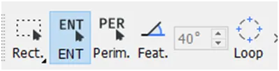
Now selecting cons
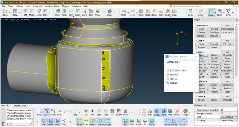
Hit the middle click the new popup opens and also a preview is showing as shown below
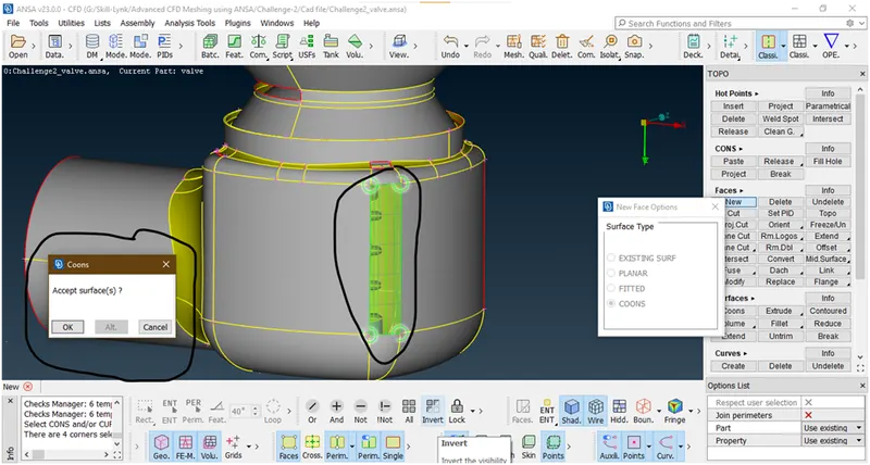
Just cross checking in wireframe mode is it selected a correct coons
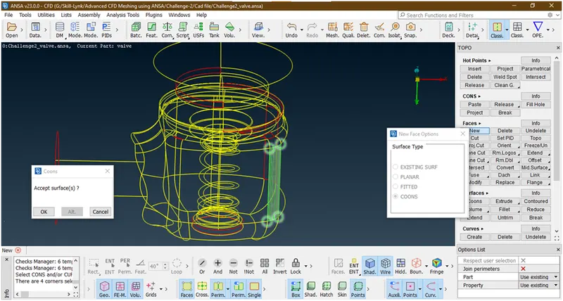
Now click on ok accept surface and we have cleared this error.
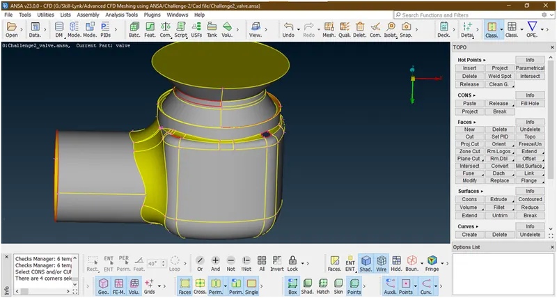
- Lets go for next error
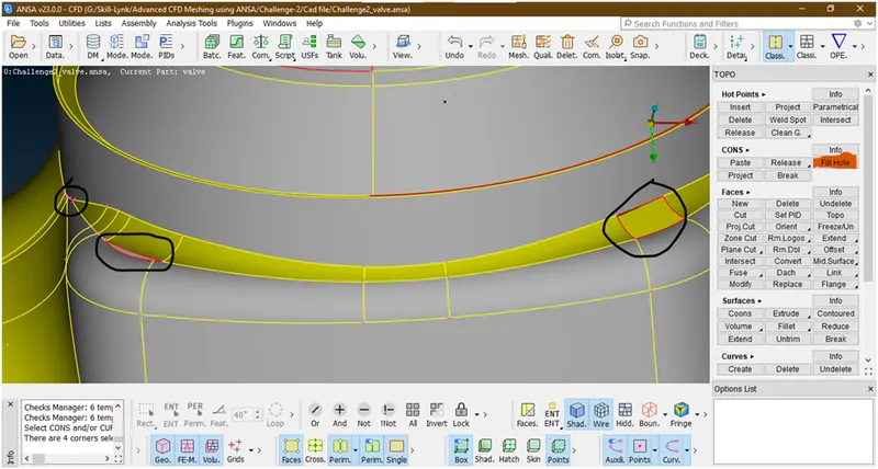
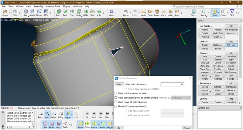
Lets clear this errors by using ‘fill hole’ tool.
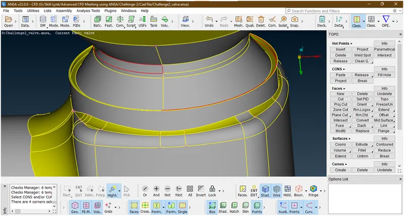
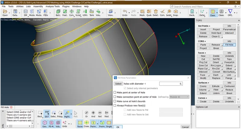
Now its clear.
- Now we are go for next error and clear it
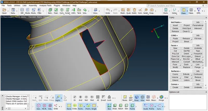
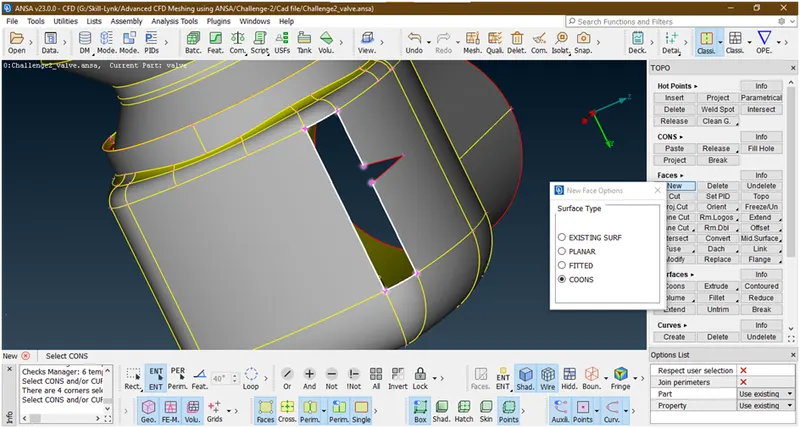
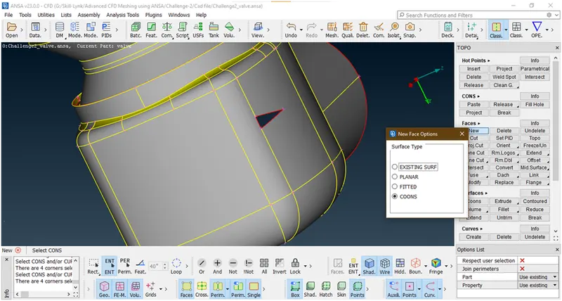
This will cleared by using
- New(under faces)-> cons by choosing entity mode
- Fill hole
- Now we are going for next error
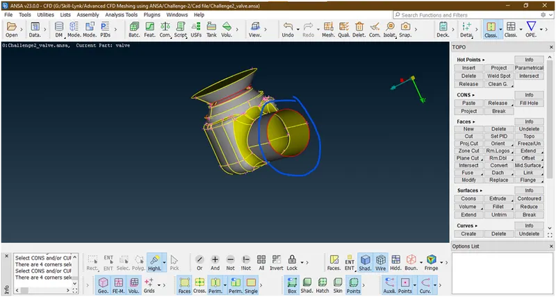
To clear this now I am using another tool
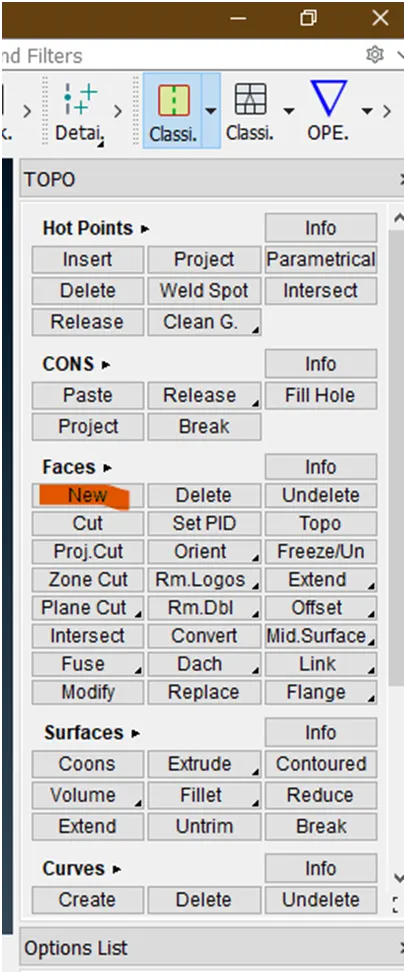
New popup shows
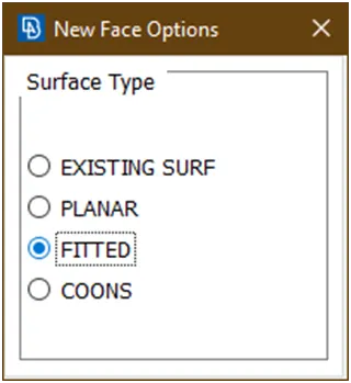
Now select the cons by selecting loop option
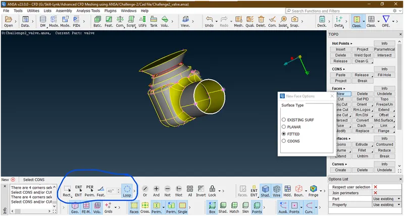
hit the middle button of mouse the preview shows as follows
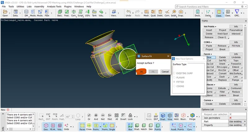
New popup highlighted then click on ok
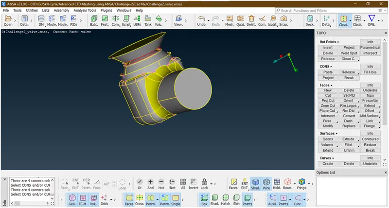
Now its clear.
- Lets go for next error
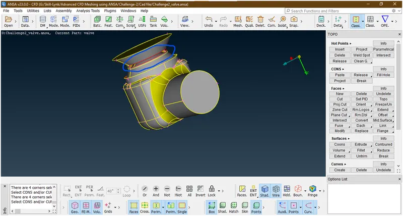
Now this will clear by using cons and loop option
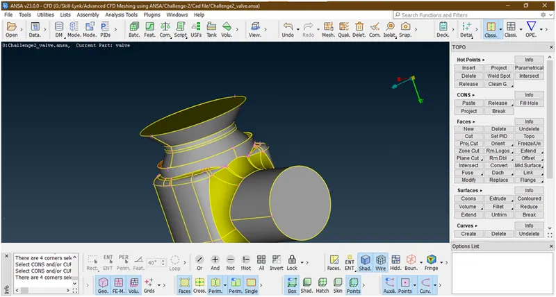
- Lets go for next error
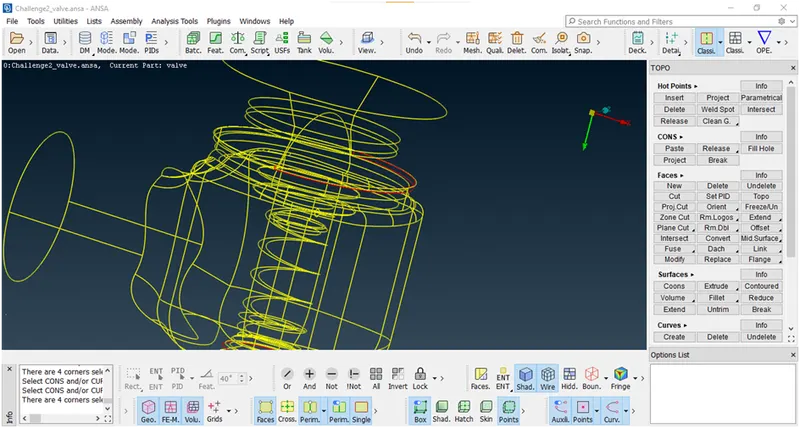
This surfaces are missing inside the geometry so we are hiding some above surfaces by using not tool.
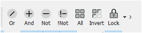
Selecting these below surfaces to hide
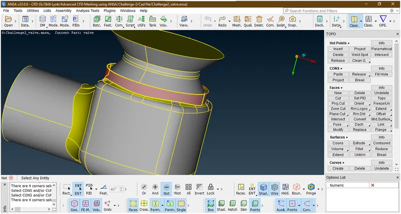
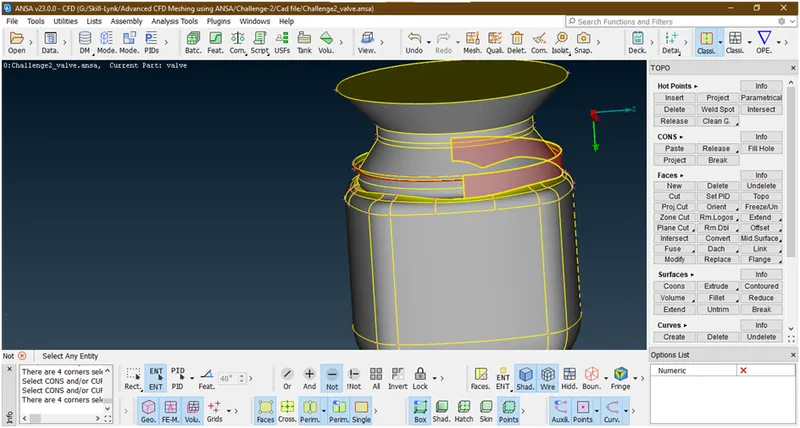
Now finally we are able to see error
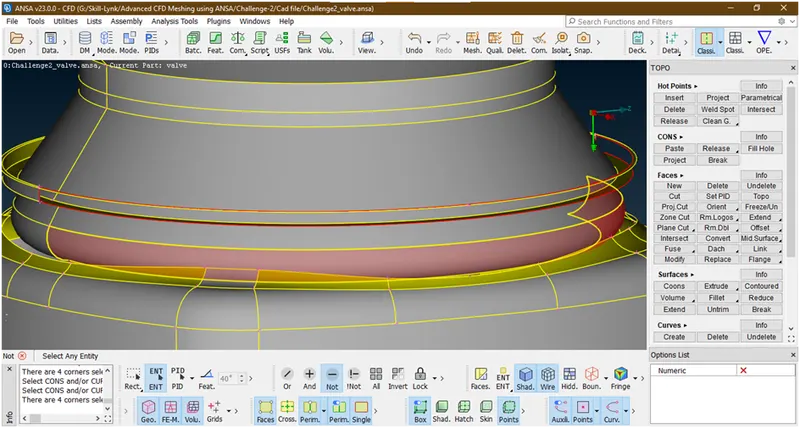
Now clear these single cons by using cons option under faces with loop mode
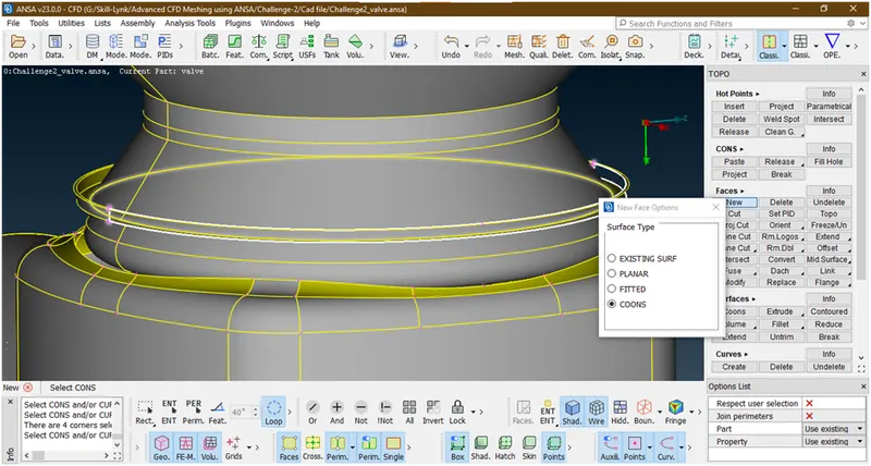
Hit the middle click of mouse
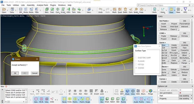
Now its preview is showing click on ok for accept surface a new surface is created.
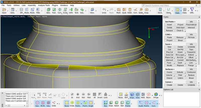
Now click on all
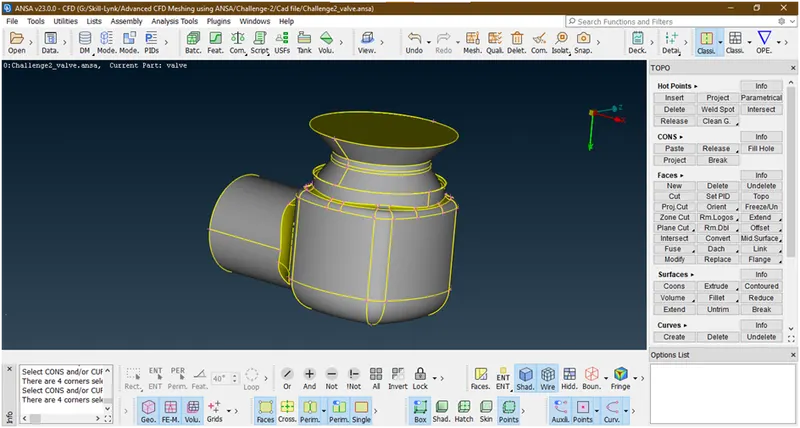
- Now again check for is any geometry error remains
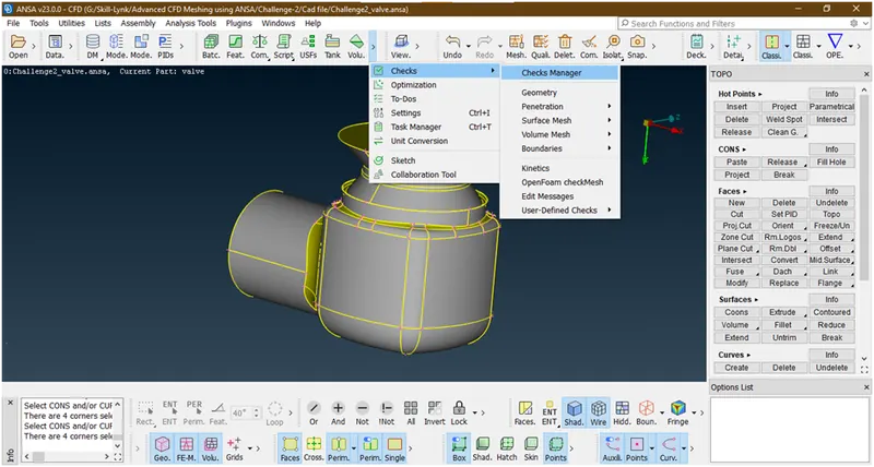
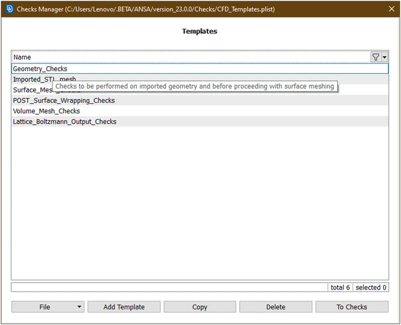
Double click on geometry checks the popup shows as shown in below figure
Click on execute
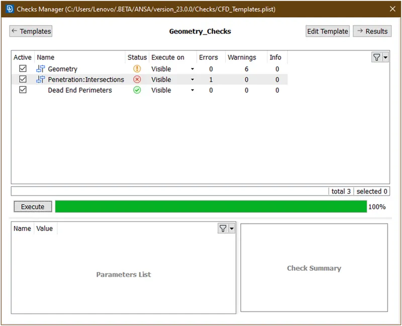
Now its showing warnings for geometry.lets see what are these
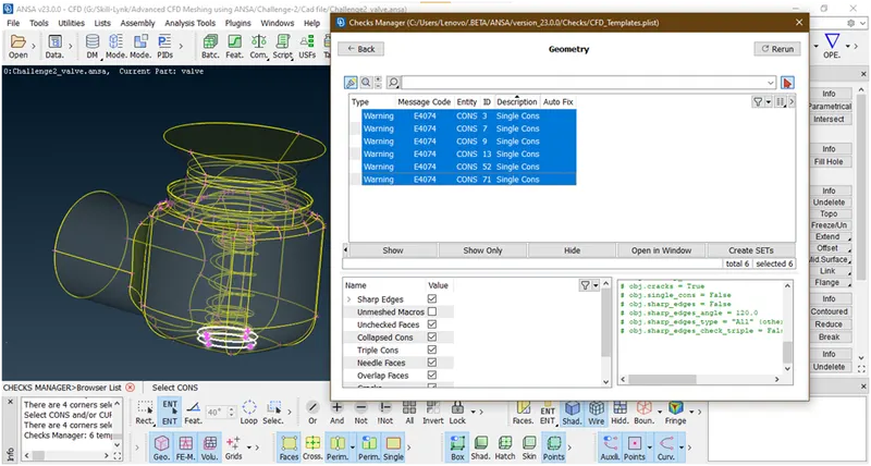
These are the single cons .so clear these.
- To clear above single cons now we are hiding front surfaces by using not option and concentrate on inner part
We have hide other surfaces and concentrate on below surface.
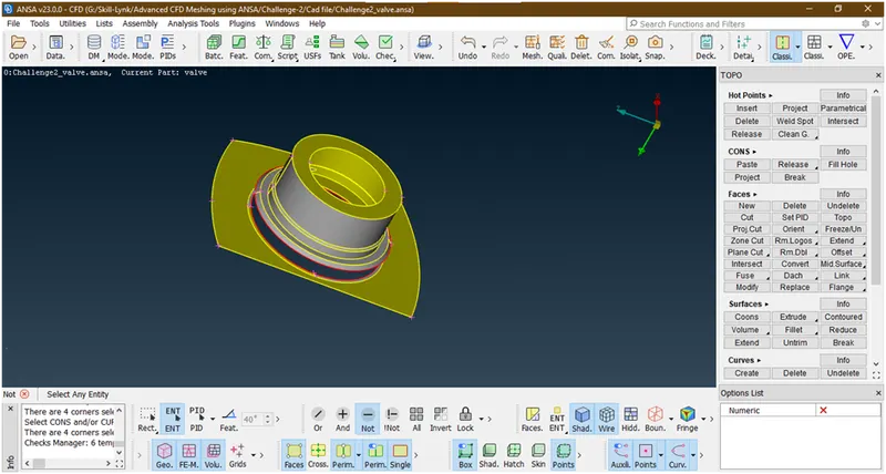
Before going to clear these erros first lock the geometry so that after if we click on ‘all’ the hide surfaces not again come and not repeat the procedure of hiding surfaces again.
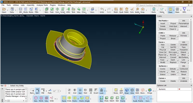
Now we have lock.
To clear this error firstly we are go for create a new surface by using entity mode ,cons under new under faces as shown below
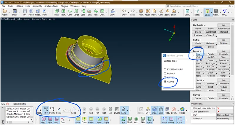
Now select the parallel cons
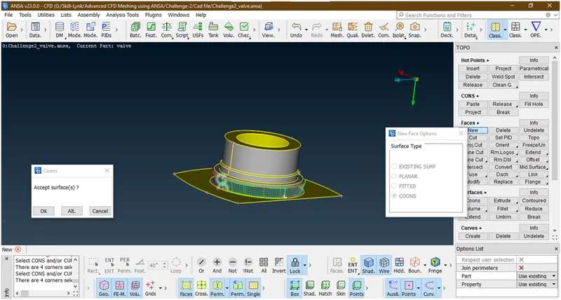
Checking in wireframe mode
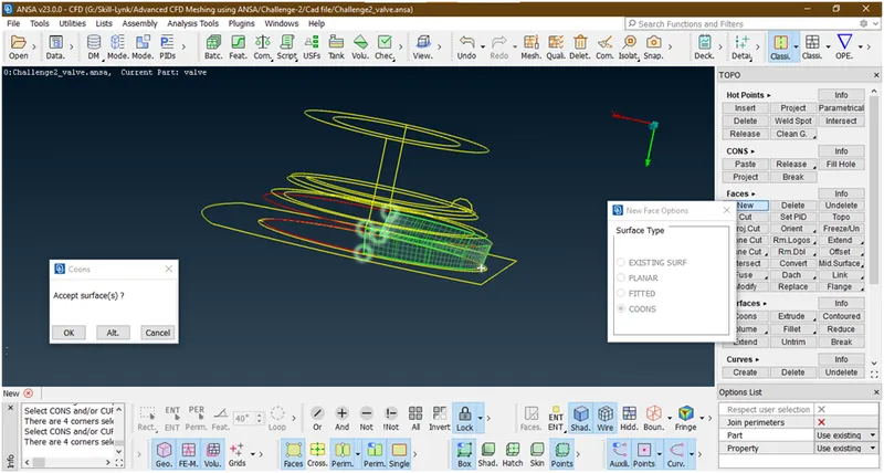
Now click on ok.
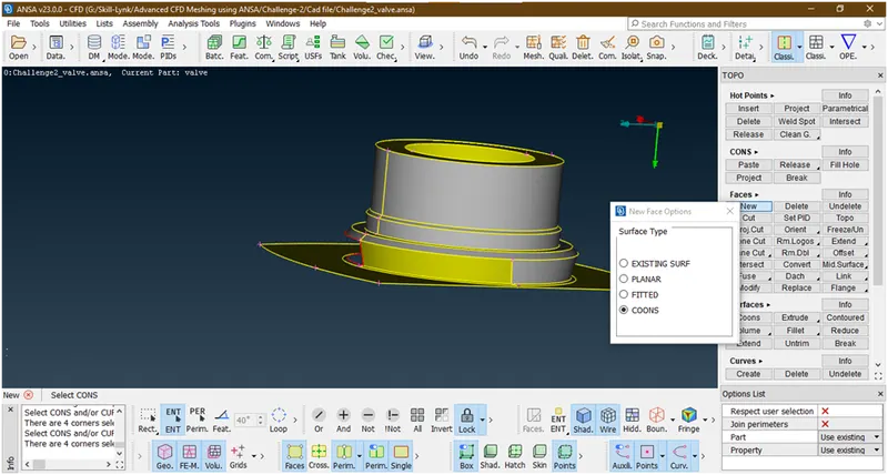
Now the surface is created.
Now to crate the half part we are going for loop option and selecting the cons.
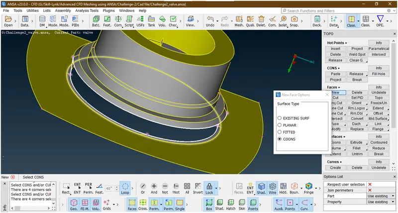
Hit middle click.
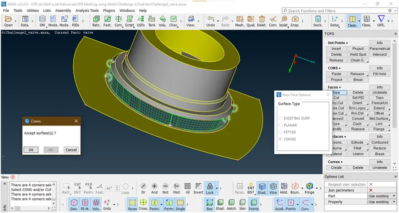
Click on ok.
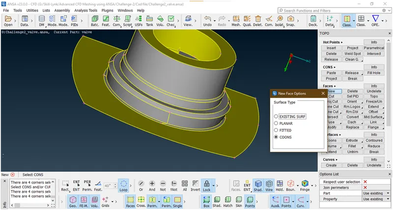
Now the surface is created.
Now remove the lock and click on all
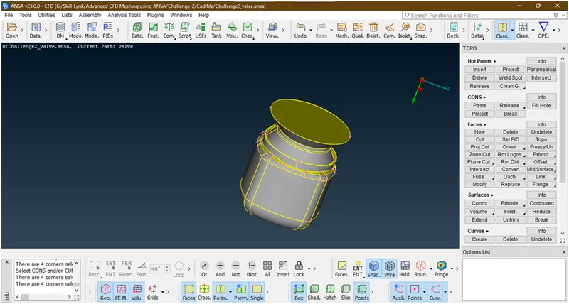
Now all surfaces are showing.
- Now again check for any errors by using check tool
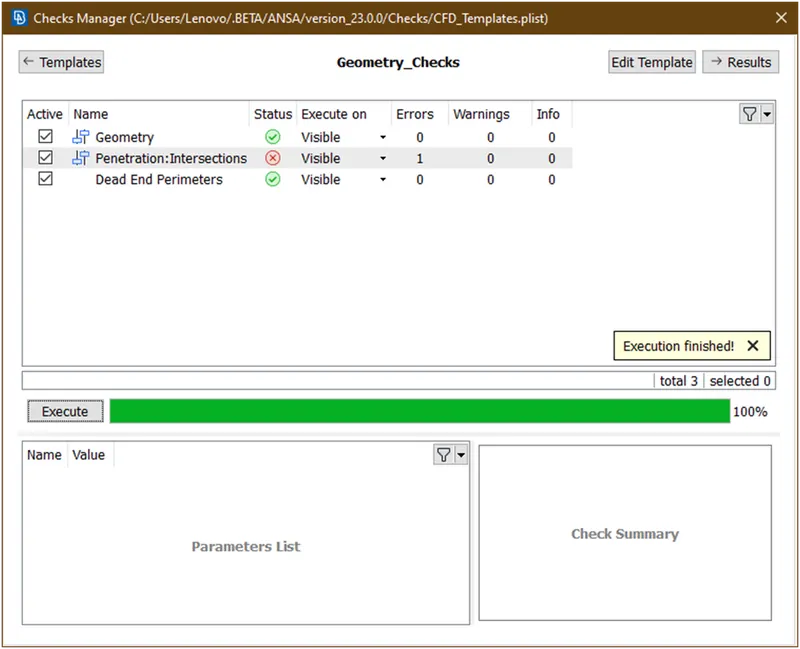
Now its showing only intersection error.lets see what is this
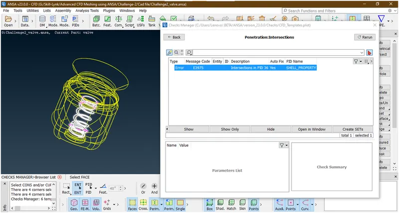
Its showing in spring and column. so lets clear it.
- This is in entity mode.
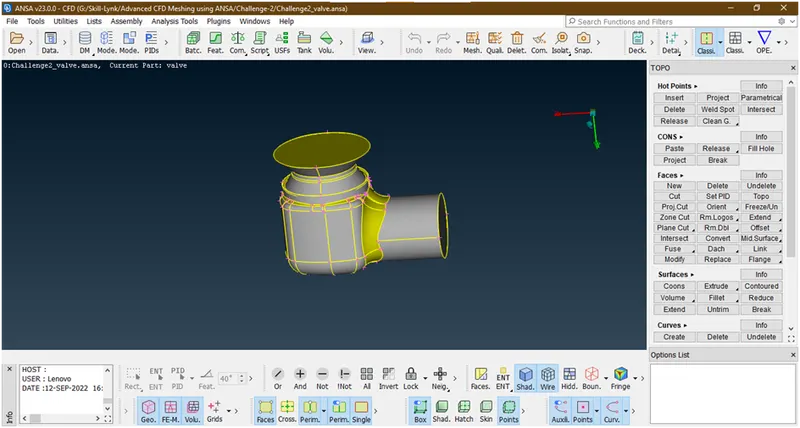
Lets convert into PID-mode.
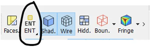
Click here you will get pid option
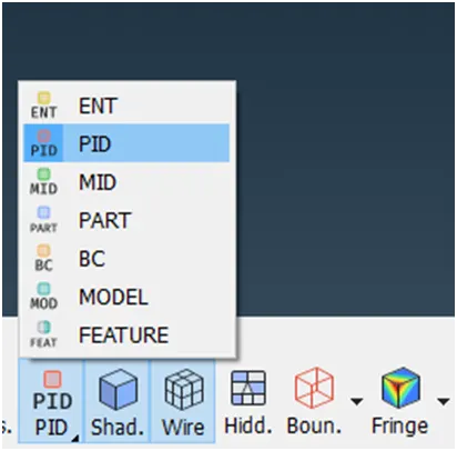
Then click on this we will see geaometry as
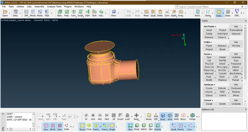
Lets assign ‘PIDs’ to each component and give name.’PID’ is nothing but just a property id.
- Click on pid tool
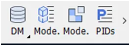
A new popup opens
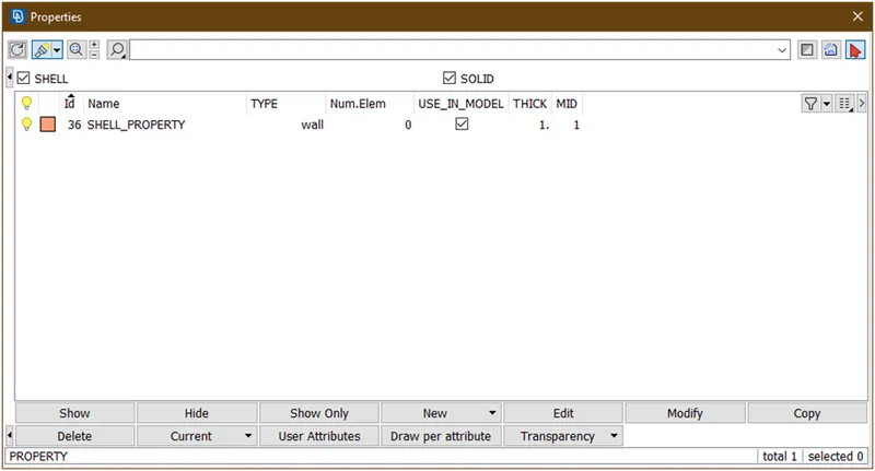
- Click on new,then it as
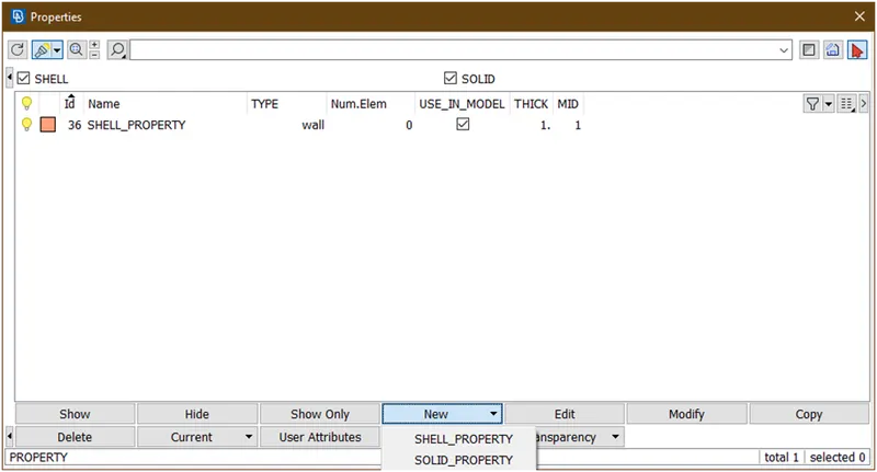
Click on shell_property,a new popup opens,then give the name of component which we want and click on ok.
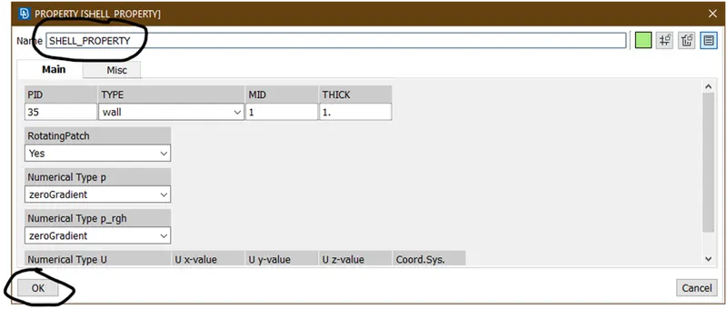
Now its created as ‘Inlet’ as shown below
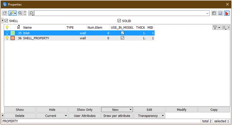
Now lets assign the face to the inlet.
For that right click on inlet
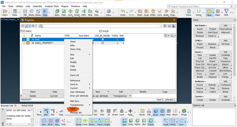
Click on apply
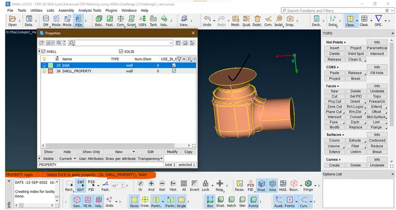
Now its ask for selecting the face
Then click on face which we have to assign.
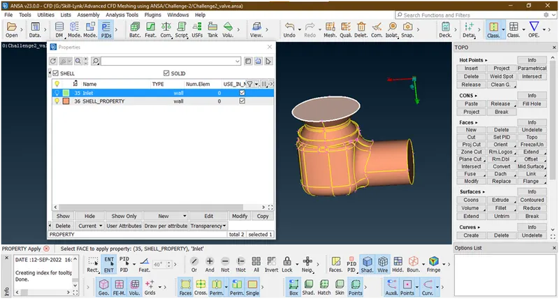
Now click middle button.
It will apply and looks like as follow
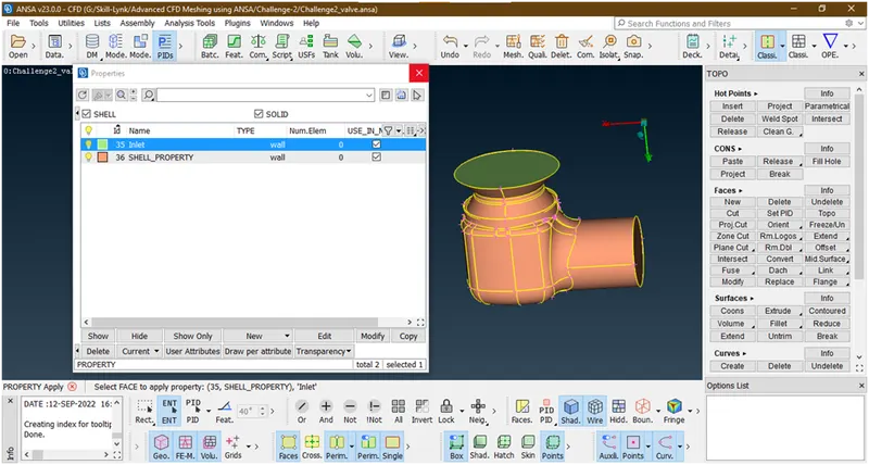
Similarly we are assigning the outlet
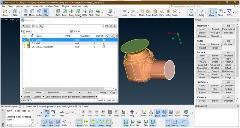
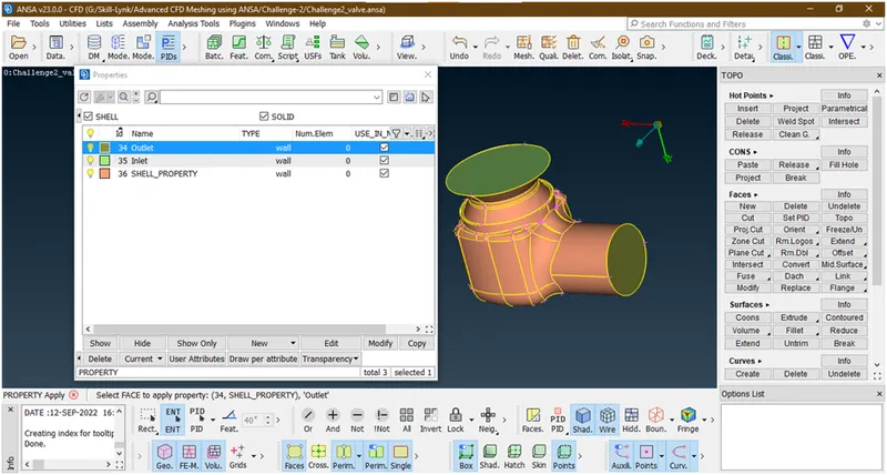
- Lets hide inlet and outlet by clicking on bulb it will hide as follows.
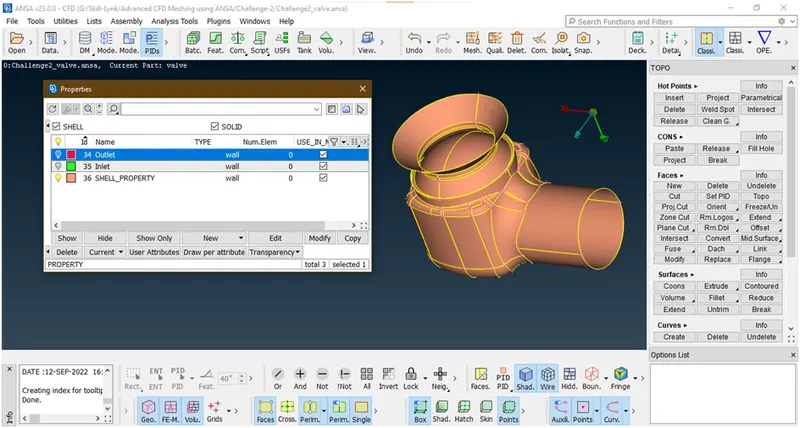
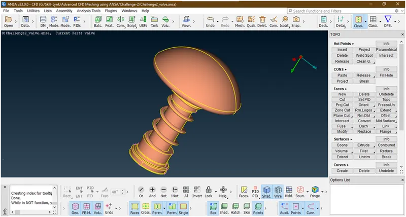
Lets isolate column,column head and spring by hiding surfaces by using not option

Now they are isolating
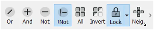
Click on lock for further operation
This tool will lock the entity which we do hide so that after that if we do another Boolean operation and click on all the oter parts which are hide before lock doesn’t come.
Now,lets assign spring
Select inot
Go to pid region
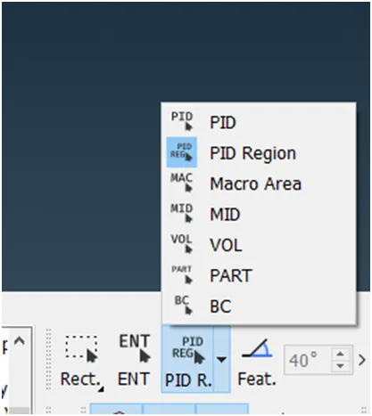
Now select geometry
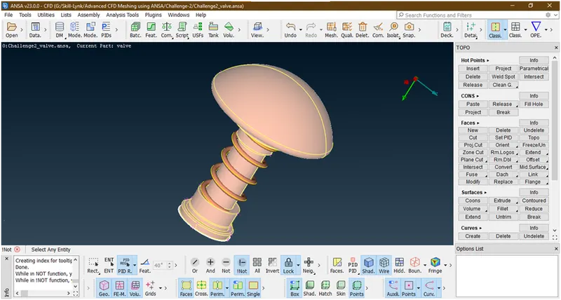
Click middle button, after that below screen shows
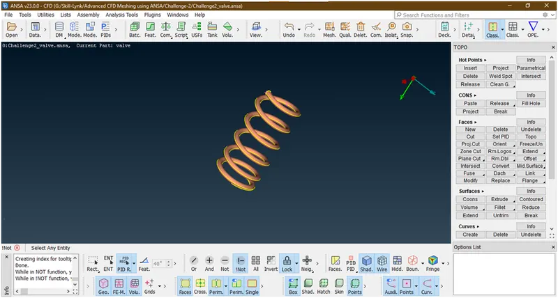
Then goto pid manager and add spring as shown the procedure of creating new pid
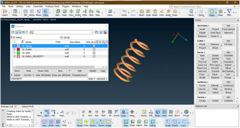
Now its created
Lets assign the spring to this pid
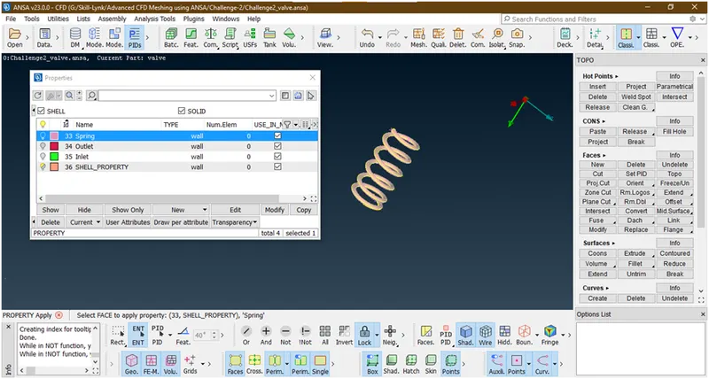
Click middle click
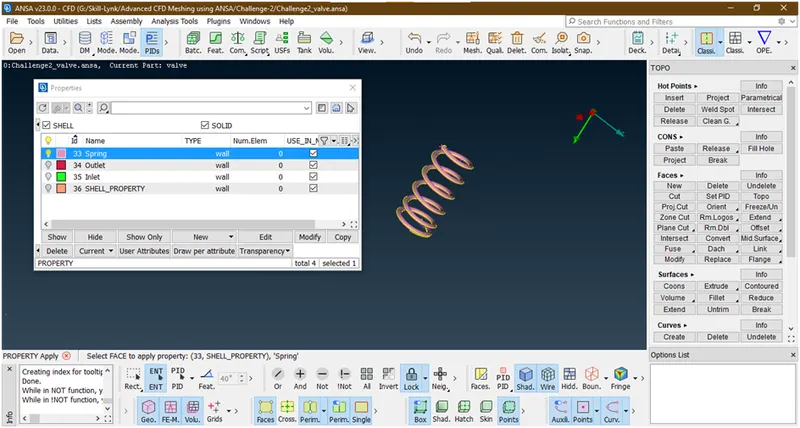
Now its assign.
Click esc.
4. Lets assign column and column head.
- First hide spring
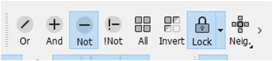
Selecting not
Selecting pid
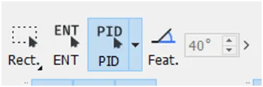
Selecting spring
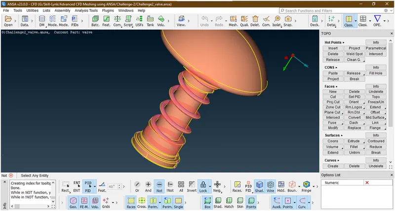
Now its hide
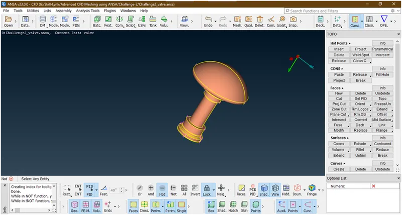
b. Lets hide column head by not tool and entity mode

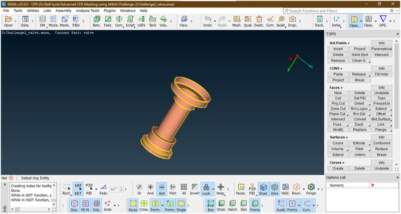
It’s a column now assign as a column
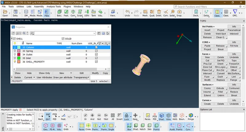
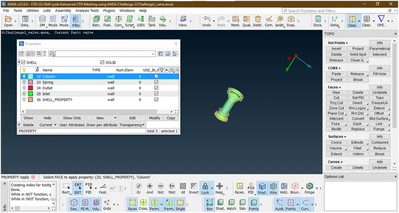
It has assign.
Now we will go for column head
Click on all
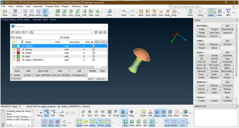
Lets hide column and spring by clicking on bulb
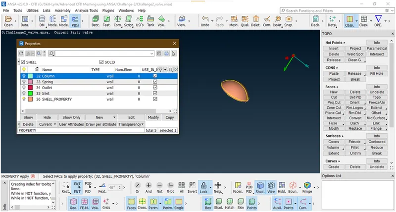
Now lets assign as column head
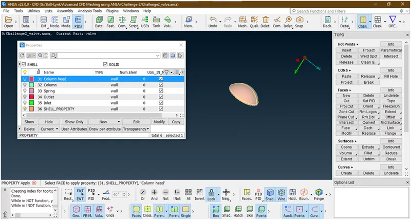
Click middle click it will assign.
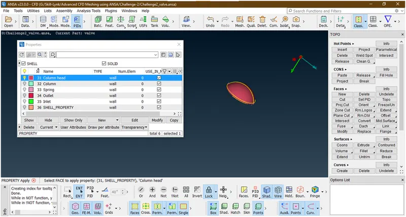
now remove the lock,and show all component
- Lets assign body by hiding all other component
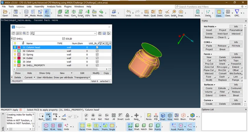
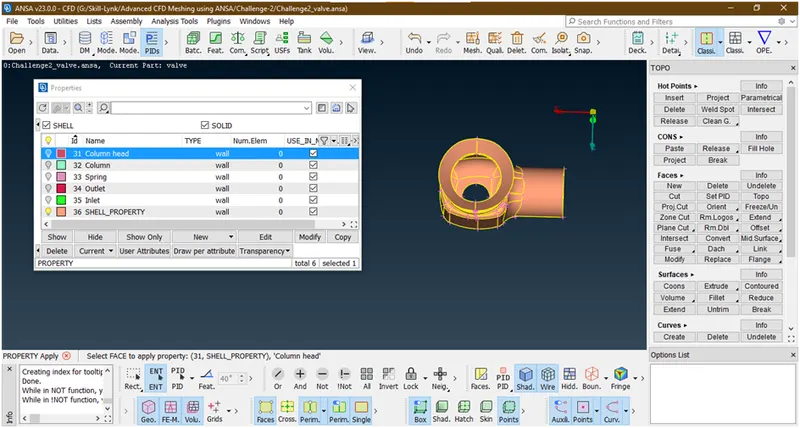
Lets assign this as a body
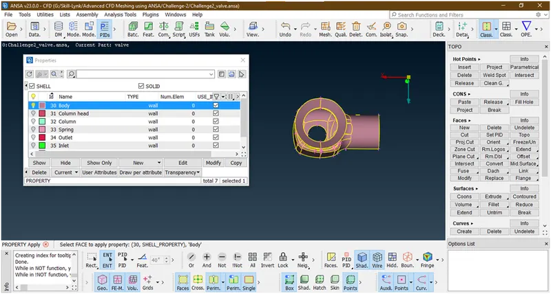
Now we assign all pids.
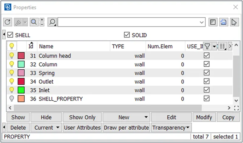
Now we have to delete this unwanted pid ’shell_property’.for that click on delete.
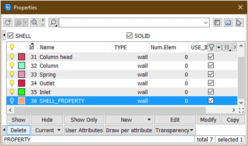
But its not gone.so we are using another option known as compress

this compress tool will delete the unused/unwanted files which are present.
Another popup opens
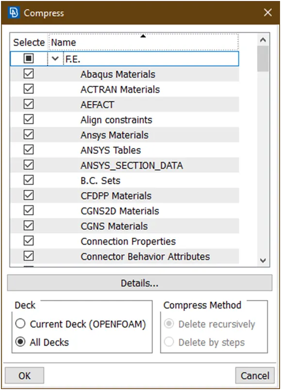
Click on ok.
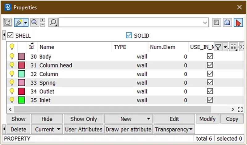
Now its gone.
- Now we are able to go for clear interaction error in spring and column. So to do that just enable spring and column
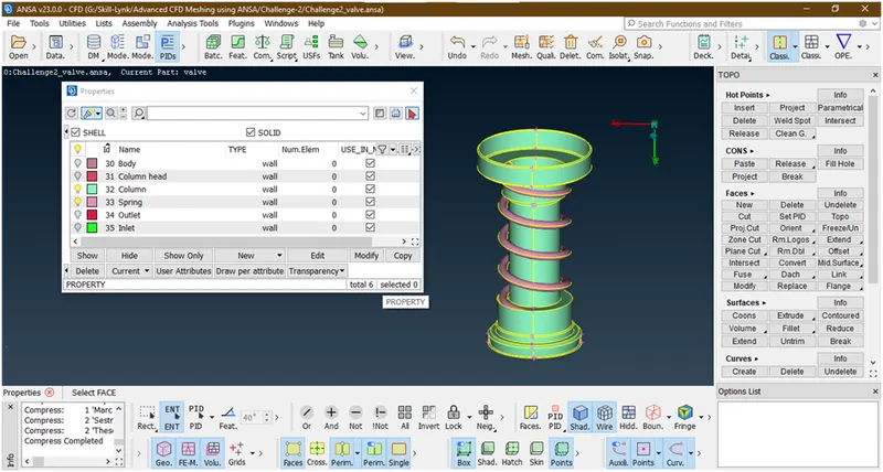
Close this dialog box and goto intersect option under faces
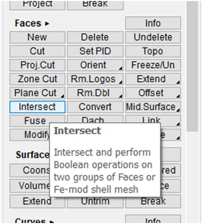
Click on this a new popup opens
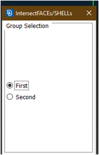
Before selecting any faces select pid
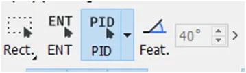
Now click spring as first
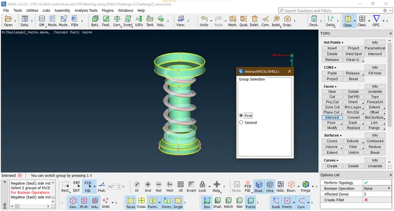
After selecting the color change
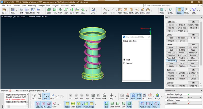
Click middle click
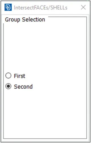
Now it asking for 2nd face again select column
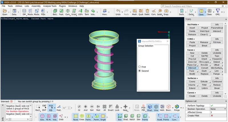
Hit middle click
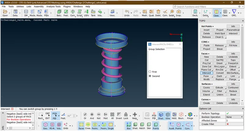
Again hit middle click a new popup opens
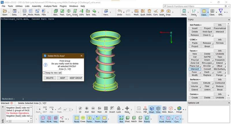
Now its asking 8 faces are intersecting we have to find out which face we want to keep and which want to delete
We are unable to see this 1st face so we go for delete.
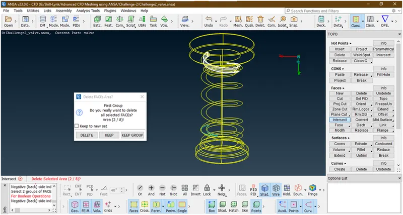
now its asking for 2nd face as shown above but we don’t want this so we are deleting this face.
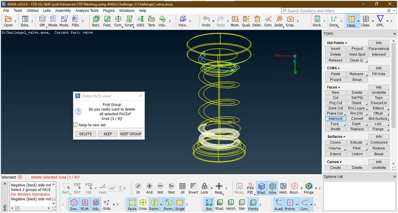
now its asking for 3rd face but it is in the column so we don’t want this,so delete this.
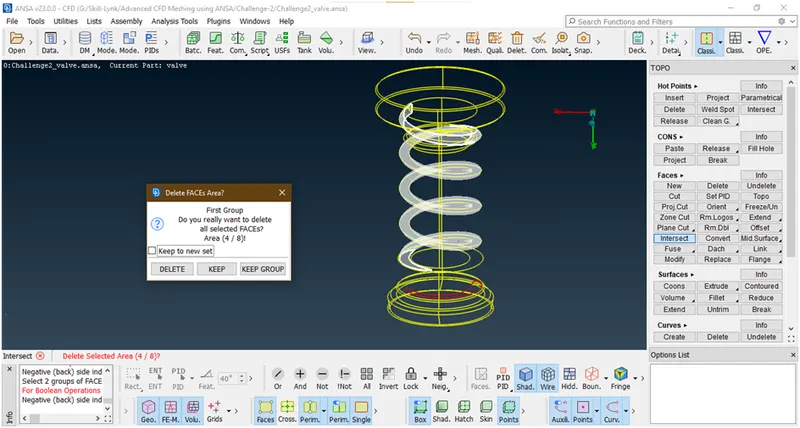
now its asked for total spring but we want this so we are keeping this
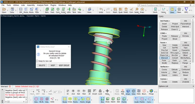
now its asking for above face but we want this so keeping this.
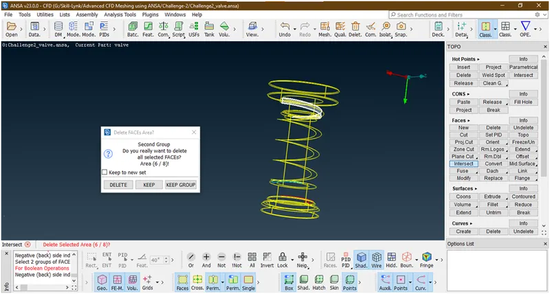
we don't want this face so we are deleting this
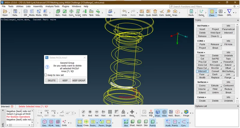
this also don’t want so we are deleting this
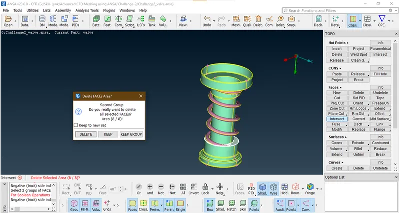
now this is asking for this face so we need so we will kept this.
After doing all intersection a new popup shows click on close
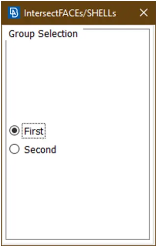
Now we are finaly clear all intersection error.
- Lets again check is there error in geometry
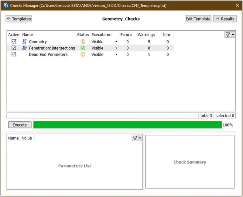
now here showing warnigs so first check in geometry
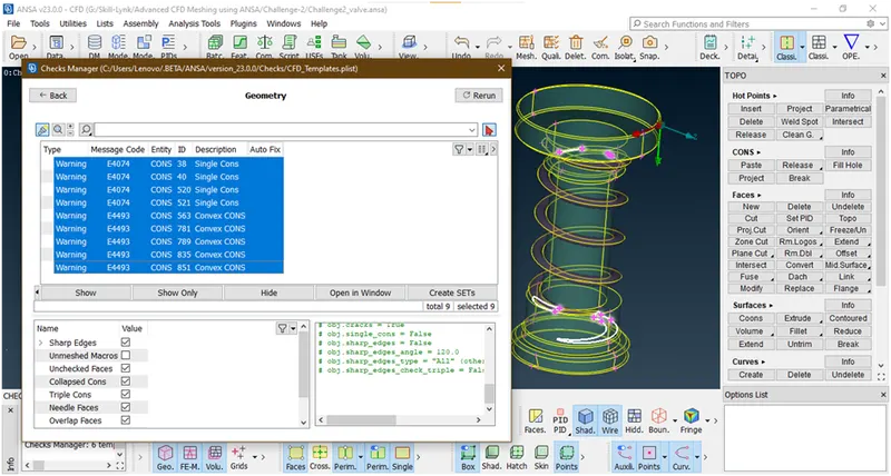
Some single cons are come lets clear all these single cons.
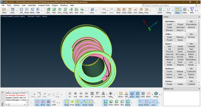
This surface is remaining part of spring but don’t need this so we are deleting this by using delete tool under faces.
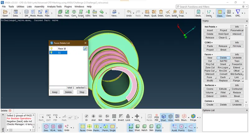
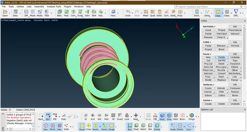
Now its deleted.
Again lets check any error remaining
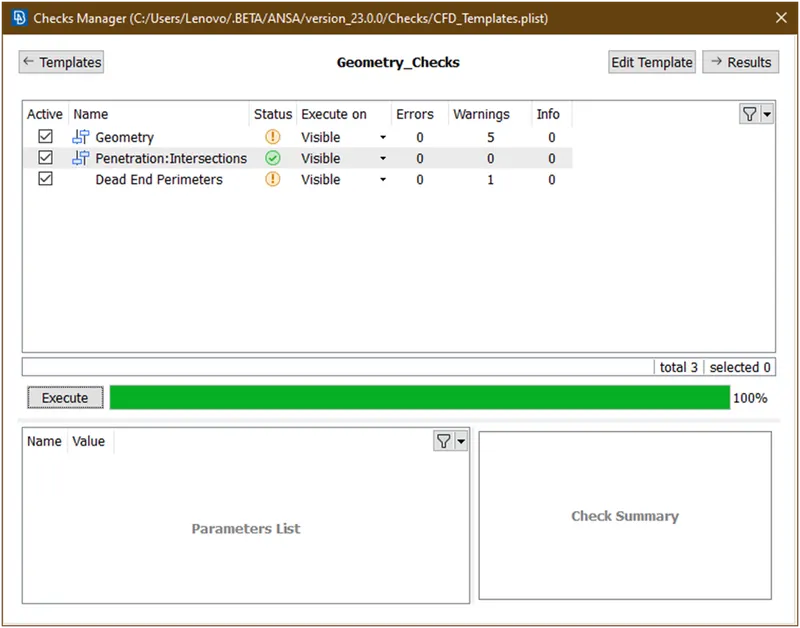
Lets see geometry
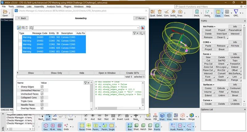
These are convex cons and are not able clear so we are ignoring.
Now lets see what is dead end perimeter
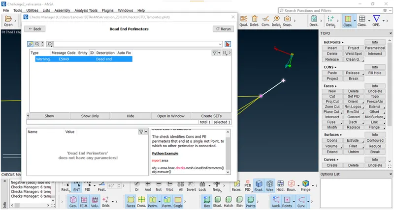
Its just a small cut so we are disableling this by using cut option.
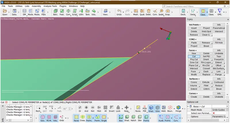
Goto this cut and right click on this cut to disable.
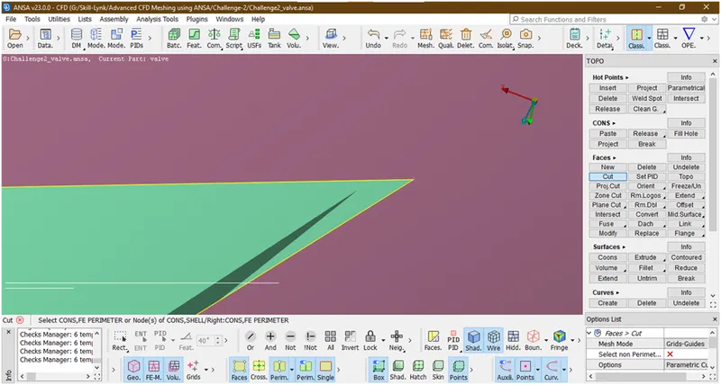
Now its gone.
- Lets on all pids
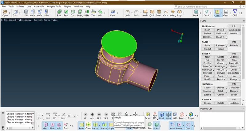
- Lets hit topo under faces
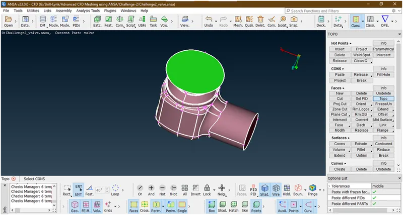
Click middle click.its done.the geometry remove all errors i.e. autofix .
- Lets delete extra hotpoints
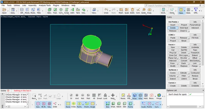
Now its deleted.
- Lets final check any errors missing
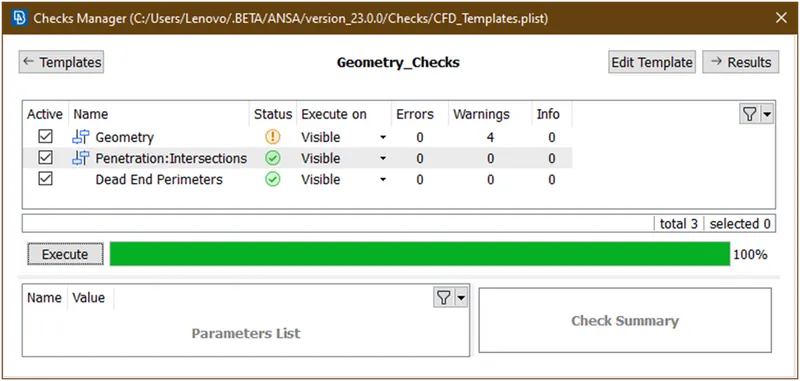
Lets see what are the geometry errors
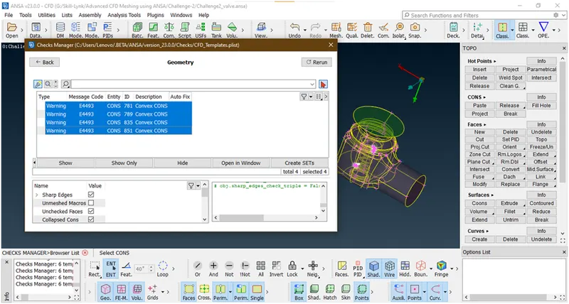
These are the concave/convex cons .so it can’t be removed.
This is concluded all geometry cleanup.
Now we are able to go for meshing.
- Now before going for meshing a small opening is at bottom we have close all openings by creating a new surface
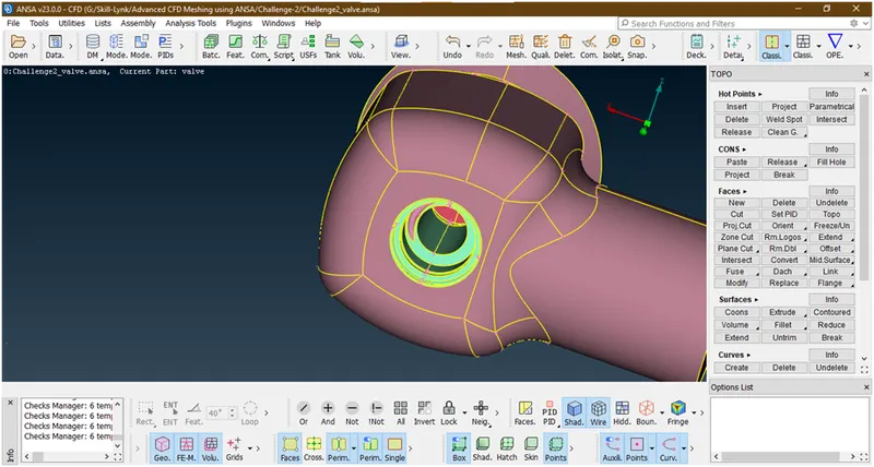
select new under faces a new popup opens as shown below
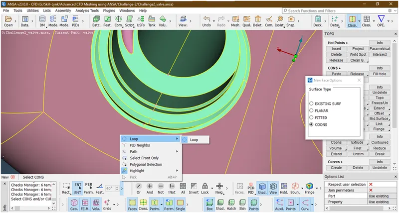
select cons and loop
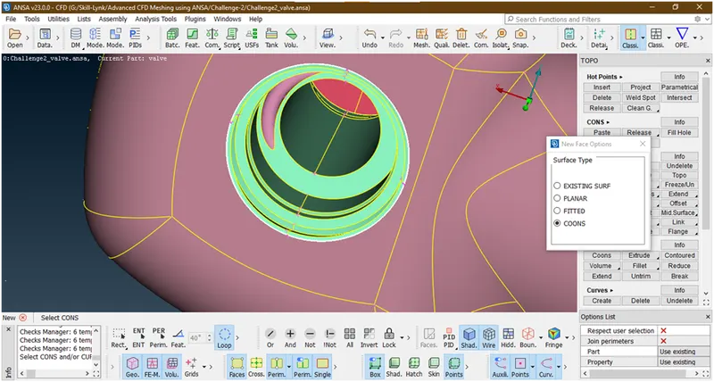
click middle click,the preview is showing as below
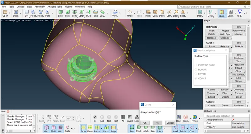
Click on accept ok
A new popup opens
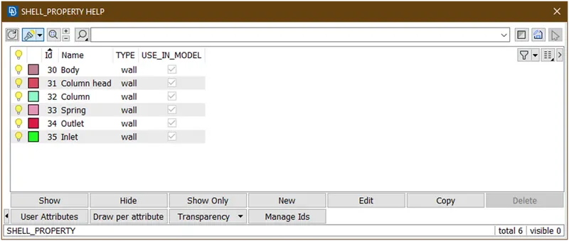
Double click on body
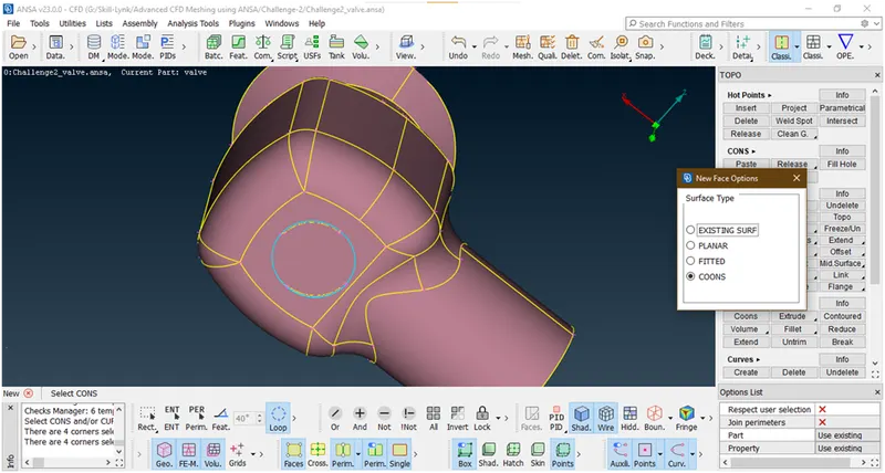
Click esc to stops operation.
Now here showing a triple con.this considered as error but can ignored this because this is required part of geometry for going meshing.
Now our all geometry cleanup done.
Lets go for meshing.
3. Surface meshing of a geometry:
- Goto classic mesh
Now we are in classic mesh.
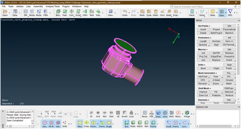
Now in question there are 3 cases are given
- Target length=5mm
- Target length =3mm
- Target length=1mm
- Element type=tria
- Now 1st lets go for 5mm meshing.
- Select mesh parameter
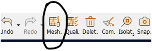
Click on this,a new popup opens as shown below
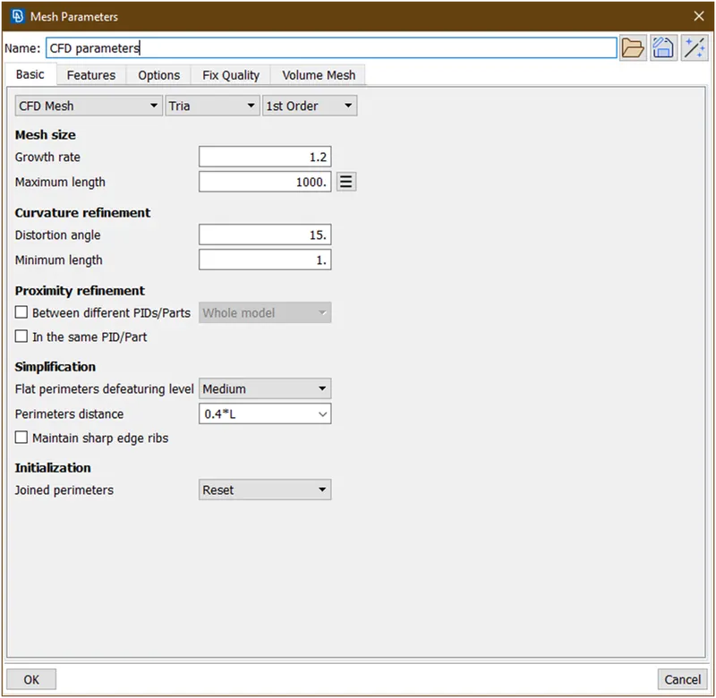
Select CFD mesh
Give maximum length=6
Minimum length=4
Click ok.
- Go to quality parameters
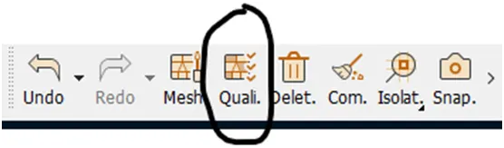
Click on this a new popup opens
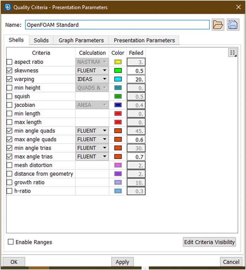
Select minimum length=4
Maximum length=6
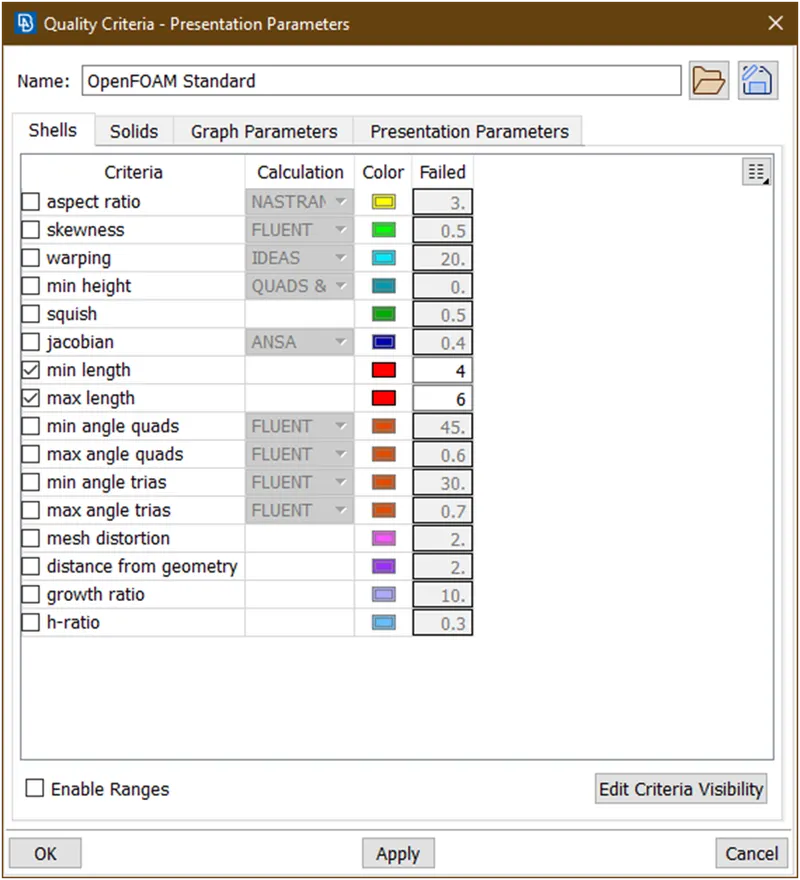
Click on apply then click on ok.
- Goto the length
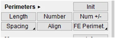
A new popup opens
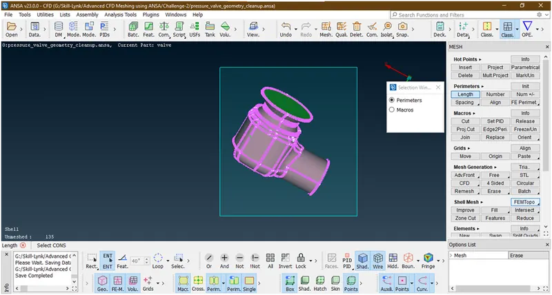
Select perimeter and select all cones, then click middle click a new dialog box opens.
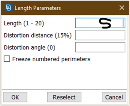
Put lenth=5 as shown and click ok.
Then click on macros and select all cones as shown below and click middle click a new popup opens
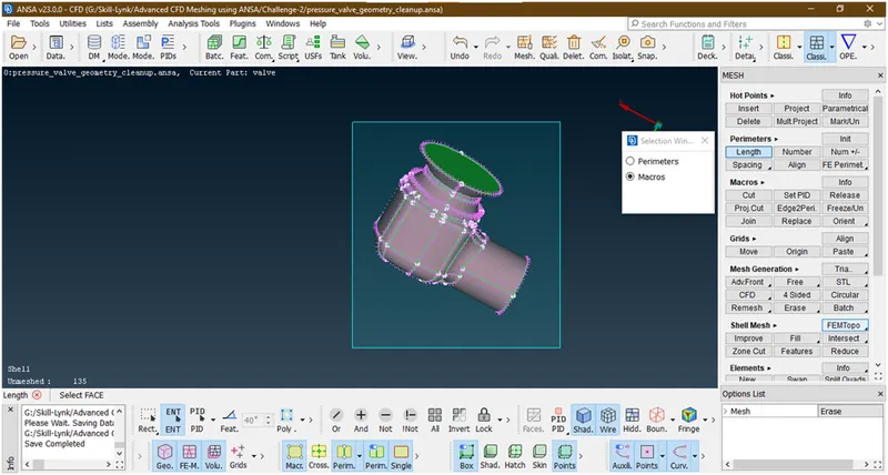
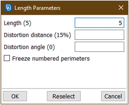
Then put length=5 and click ok.
Click esc.
- Goto mesh generation -> cfd
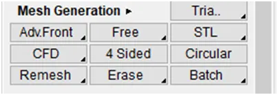
select visible
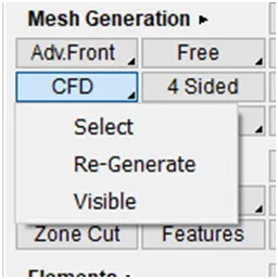
wait until meshing done.
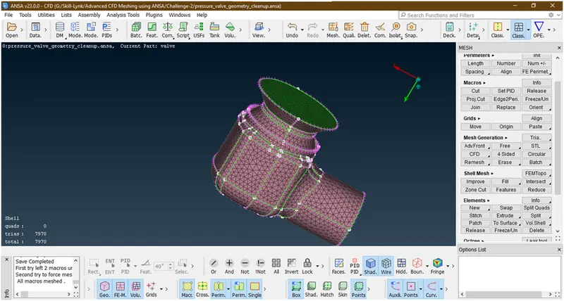
Now its meshing done.
Lets see spring resolution by hiding other parts.
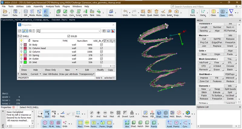
Now its not looking good and come as a failure so we discarded it.
- Lets erase this meshing
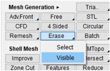
Now it has been erased.
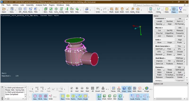
- Now we are going for target length=3mm meshing
- Again open mesh parameters
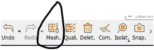
A new popup open
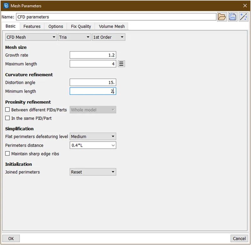
Give minimum target length=2mm
Maximum length=4mm
Click ok.
- Goto qulity parameters
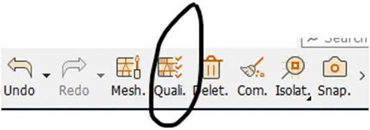
New dialog box open
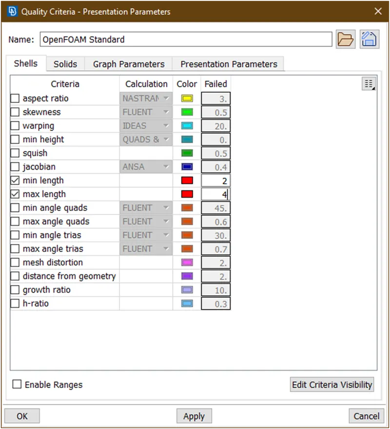
Give minimum length =2
Mximum length=4
Click on apply
Click on ok.
- Goto length under perimeter
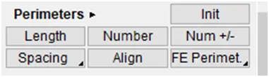
Select perimeter and select all cons as shown below
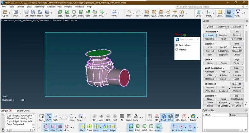
Click middle click.a new popup open give length=3
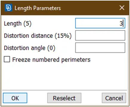
Click ok.
Then goto macros and select total geometry
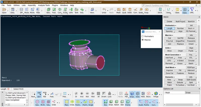
Click middle click. A new dialog box open
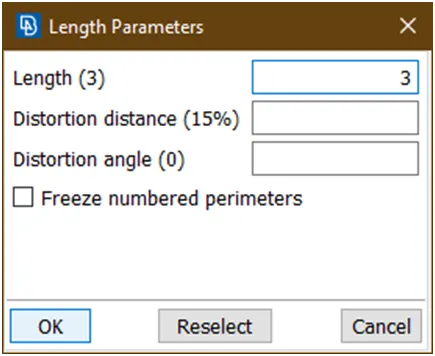
Give length=3
Click ok.
Click esc.
- Goto mesh generation->cfd-> visible
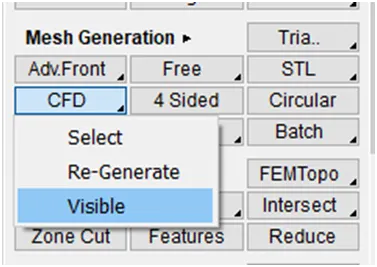
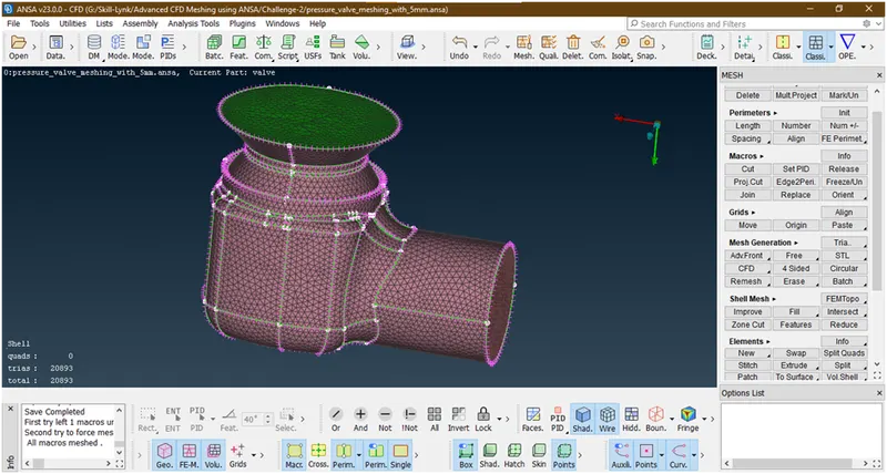
Now wait for meshing tobe done
Lets see spring resolution by hiding all other components of geometry.
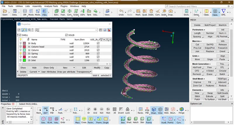
It got some shape compare to previous one but not a perfect .so we are discarding this.
Now we are erasing this mesh
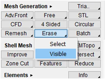
Now it has been erased.
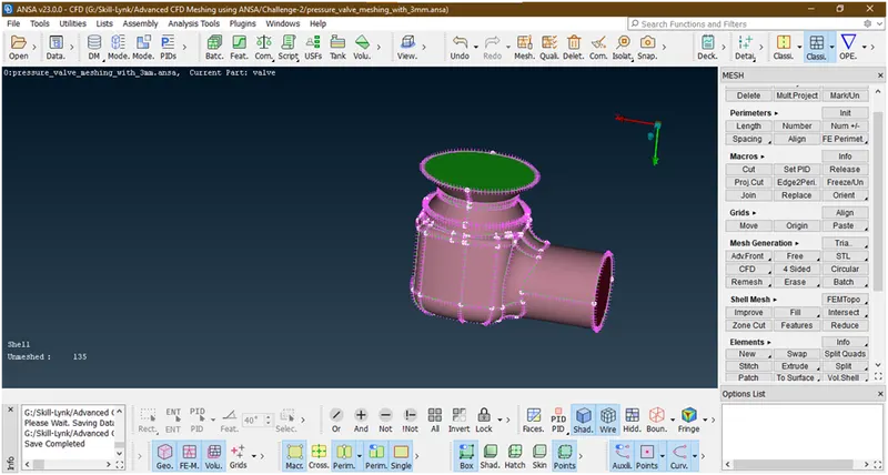
- Now we are going for 1mm mesh.
- Again select mesh parameter
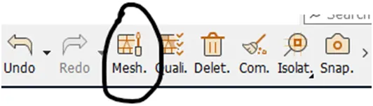
A new dialog box open
Give minimum target length=0.5
Maximum target length=1.5
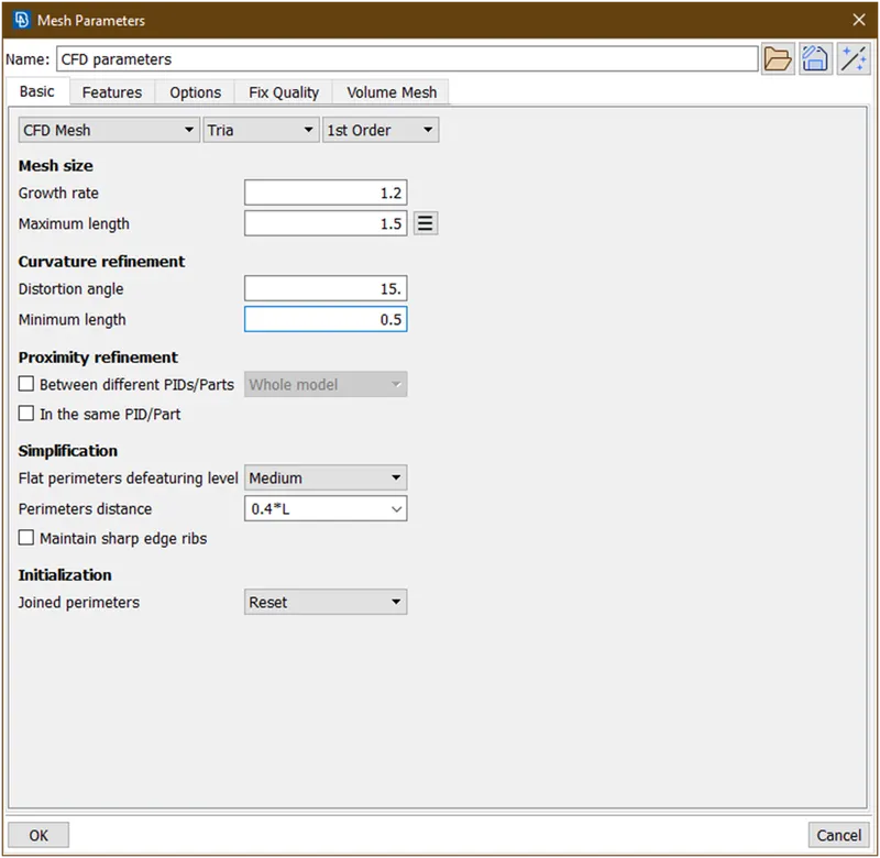
Click on ok.
- Goto quality parameters
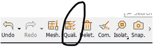
A new dialog box open
Give minimum target length=0.5
Maximum target length=1.5
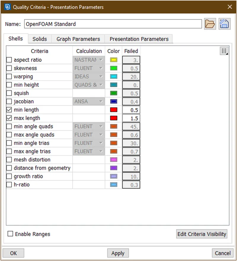
Click on apply.
Click on ok.
- Goto length under perimeter
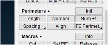
Click on perimeter then select all cons i.e. all geometry
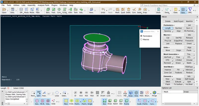
Click middle click, anew dialog box open
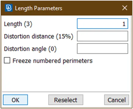
Give length=1
Click ok.
Goto macros and select all cons
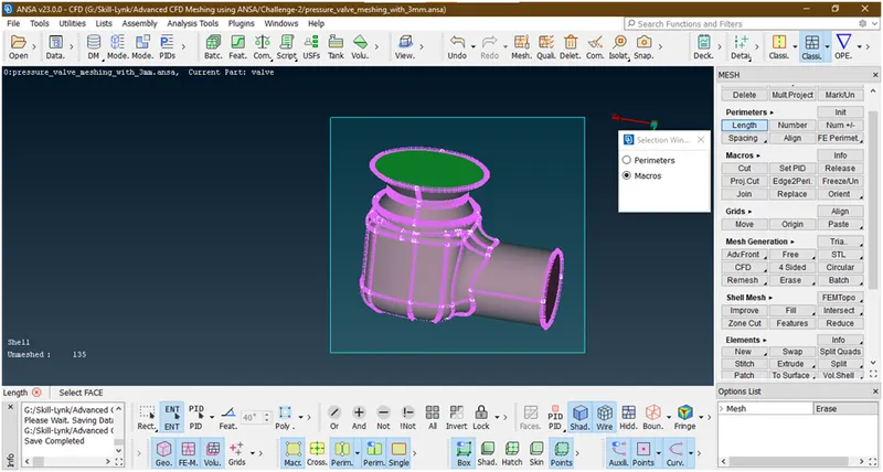
Click middle click, a dialog box open
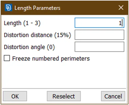
Give length=1
Click ok.
Click esc.
- Goto mesh generation->cfd->visible
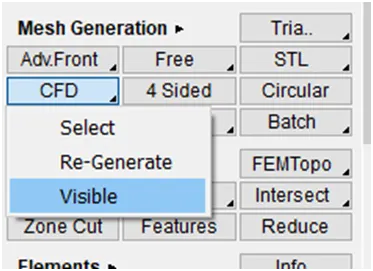
Now meshing has been done as shown below
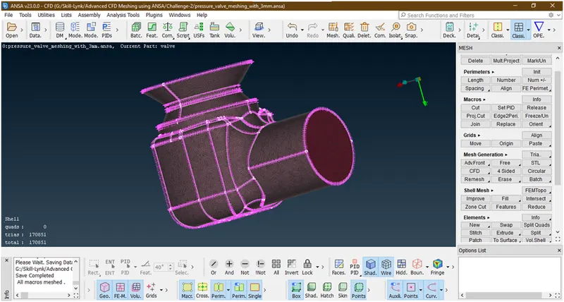
Now its looks fine.
Lets see spring resolution
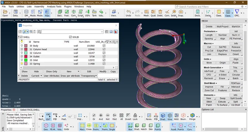
Now its looks perfect.
So it is gone acceptable.
So surface meshing is done.
Results :
- 5mm mesh
- 3mm mesh
- 1mm mesh
Conclusion :
- As we are decreasing the meshing size like from 5mm to 3mm to 1mm the computation time increases and mesh gets finer .
- here 1mm meshing gives a good results compare to 5mm and 3mm mesh.
Output files:
- Pressure valve with 5mm meshing
https://drive.google.com/file/d/1ZiKSWu00b59My3NTZ0-I4r7Gf_FQ8PM-/view?usp=sharing
- Pressure valve with 3mm meshing
https://drive.google.com/file/d/1hnBva5dvwIVDSh9ikWgJ8IVC65BcupaL/view?usp=sharing
- Pressure valve with 1mm meshing
https://drive.google.com/file/d/1VE5XWIQV55yxOZqNwxeFAdAClwADn_Q6/view?usp=sharing