Project 1 : CFD Meshing for Tesla Cyber Truck
Project-1
Aim : CFD MESHING FOR TESLA CYBER TRUCK
Objectives :
- For the given model, check and solve all geometrical errors and Assign appropriate PIDs. Perform meshing with the suitable Target length and element Quality criteria.
- Target lengths for the different parts of a model can be decided by your own. Finer mesh will give good results and will compromise with the longer processing time. Target length for different parts of model is given as below
- Body - 3 mm
- Lights - 4 mm
- Rims and Tyres - 2 mm
- Window - 2 mm
- Meshing Wind tunnel volume with tetra elements may take upto 2 days of time. So that is not compulsory to perform. As this is a major project, It is advisable to mesh that completely by taking some days of time. Write a detailed report for the same.
Note: All the 2D elements(Trias) in your model should clear the quality criteria (i.e. Off elements should be zero). Depending upon this you will be awarded marks.
Procedure :
1. Importing geometry:
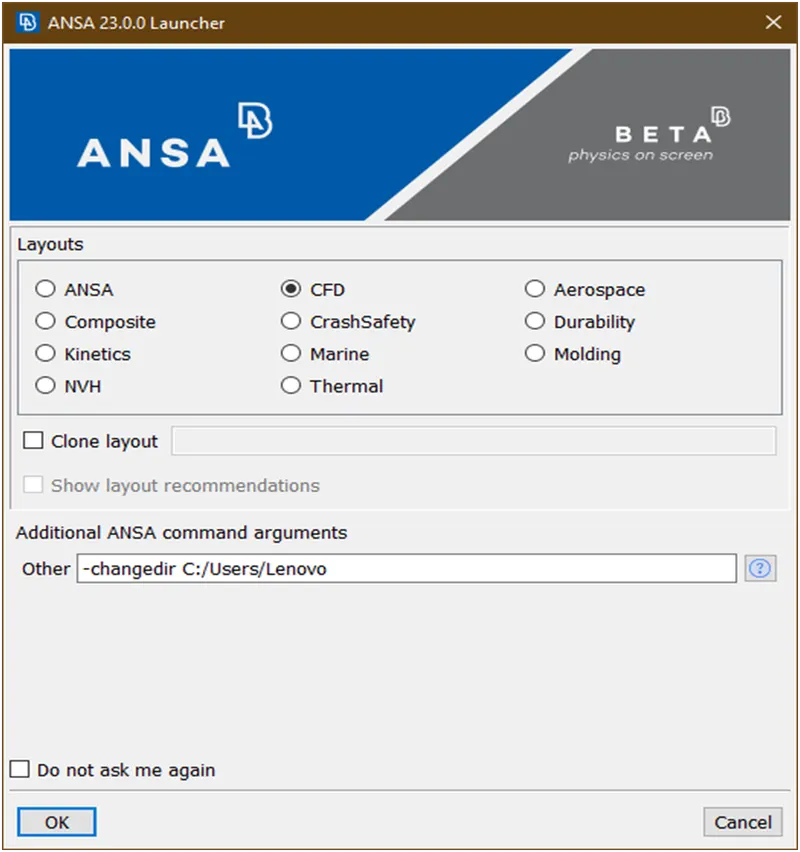
- Open the ansa software then the dialog box come as shown in below figure and For CFD applications it is recommended that ANSA is started in CFD mode, by selecting the corresponding option from the launcher window. This will allow the better setup of the software interface for CFD pre-processing.
- At ansa command argument write ‘-performance_mode 3’ for smooth running the software in regular laptops/pc because to run the this software we required high configuration but our pc’s are not build to run these softwares as shown in below figure
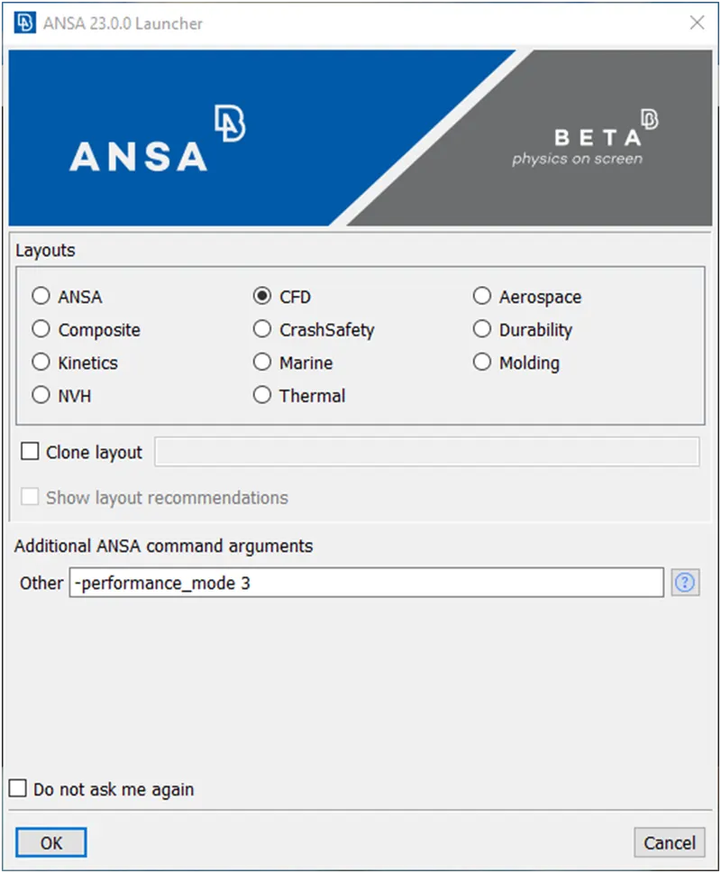
Then click on ok.
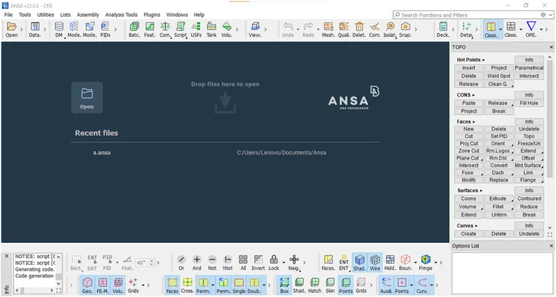
- Now the ansys user interface is open as shown in below figure.
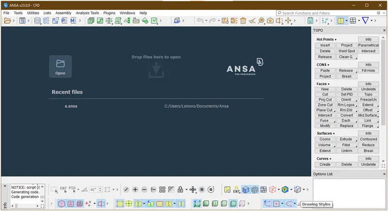
- Now ,right click on bottom menu then the dialog box is open as shown in below and find show lables and click on radio button.
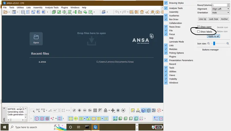
Now the lables will show as shown below figure.
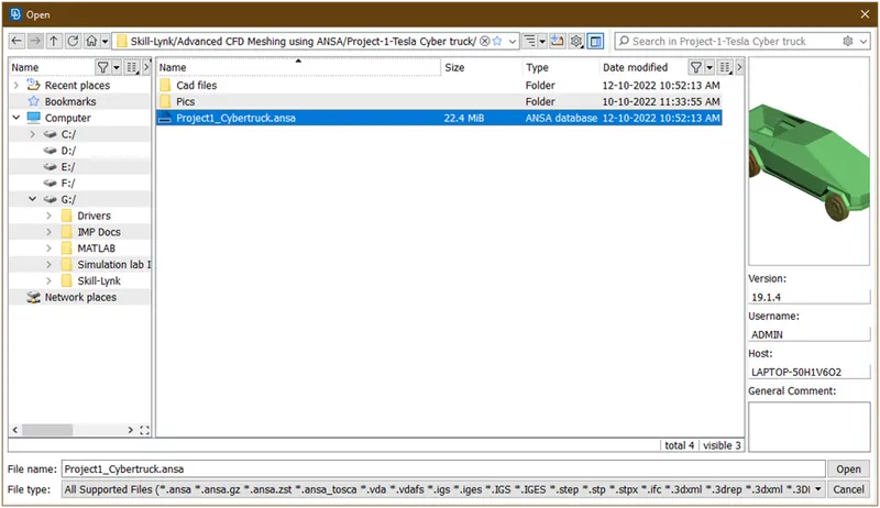
- Open the ansa file which is required here.
Now the geometry looks as
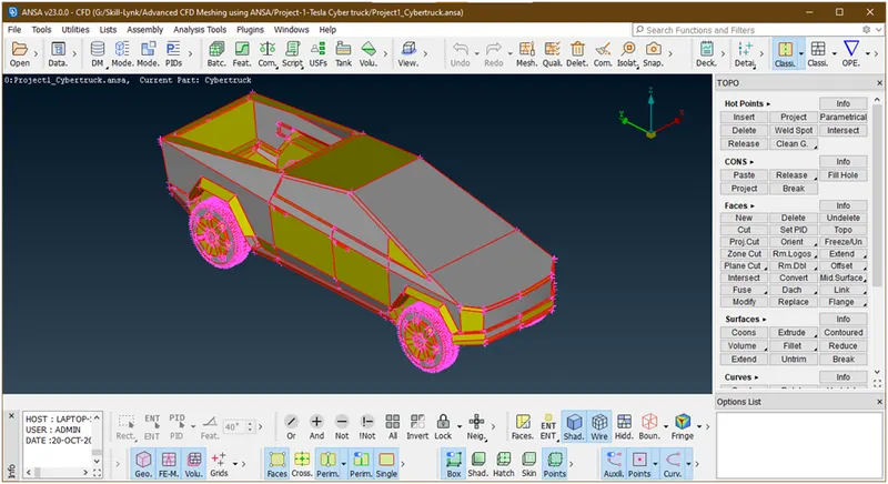
Now we are going for geometry cleanup.
2. Geometry Cleanup :
- Lets goto the classic topo mode for grometry cleanup.
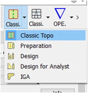
The user interface looks as
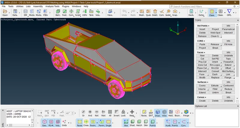
- Now this geometry looks as there is not proper connection was established. All over the geometry the red cons seen.so lets hit a topo.forthat goto faces-> topo -> box selection of geometry-> hit middle key.
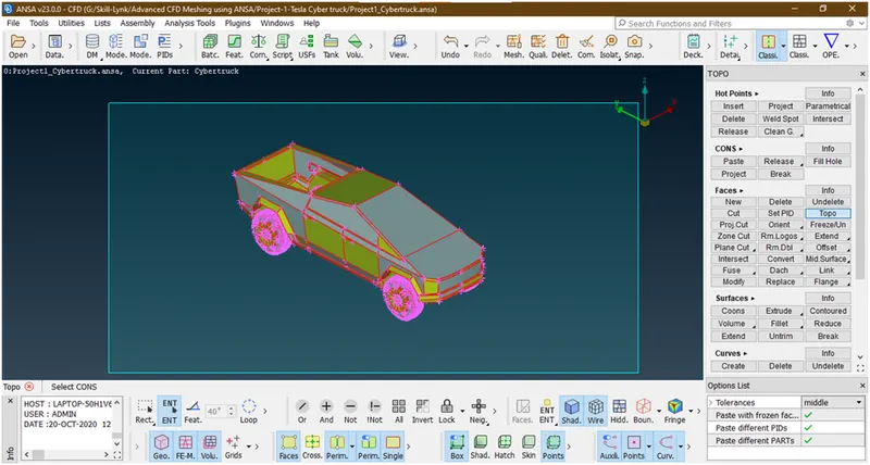
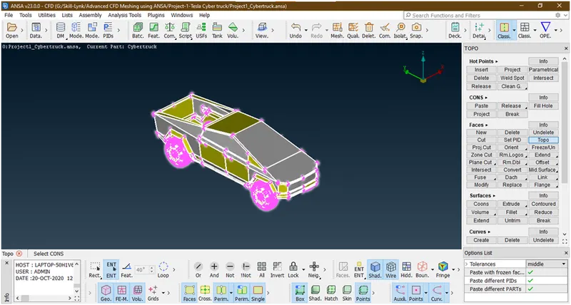
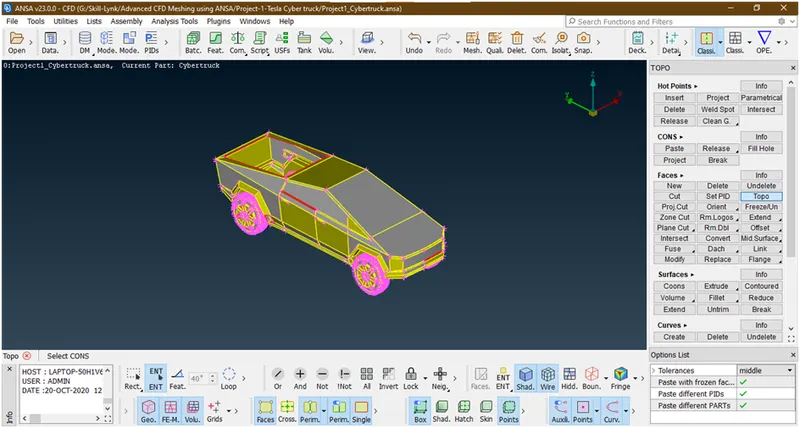
It done . the connections are established and yellow cons shown.
- In the above geometry some red cons are visible.this is due to missing surfaces. Lets try to make surfaces there.for that goto faces-> new-> select proper options-> select feasible selection mode as shown below.
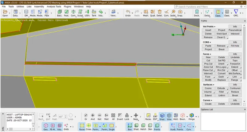
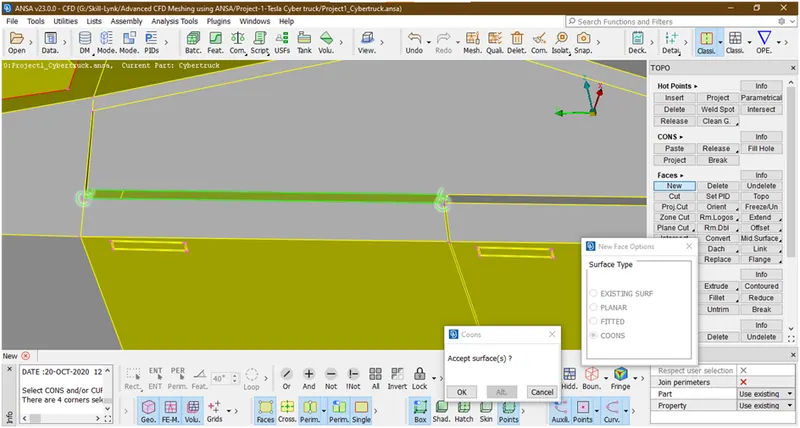
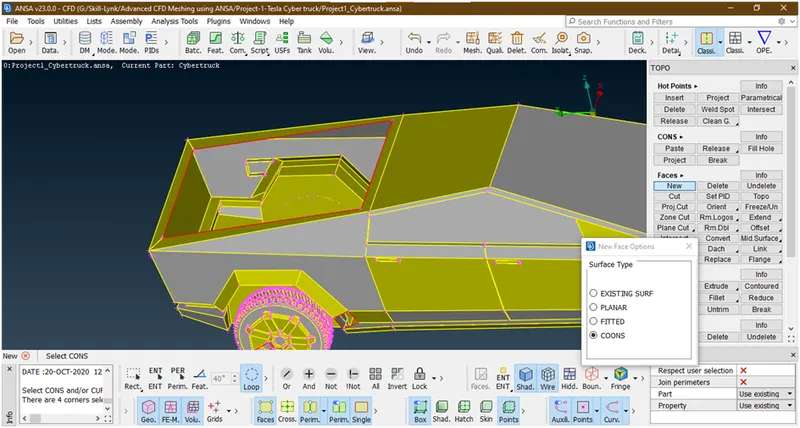
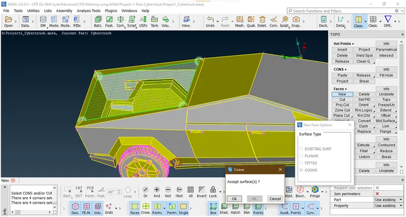
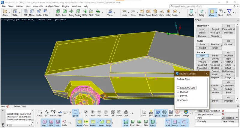
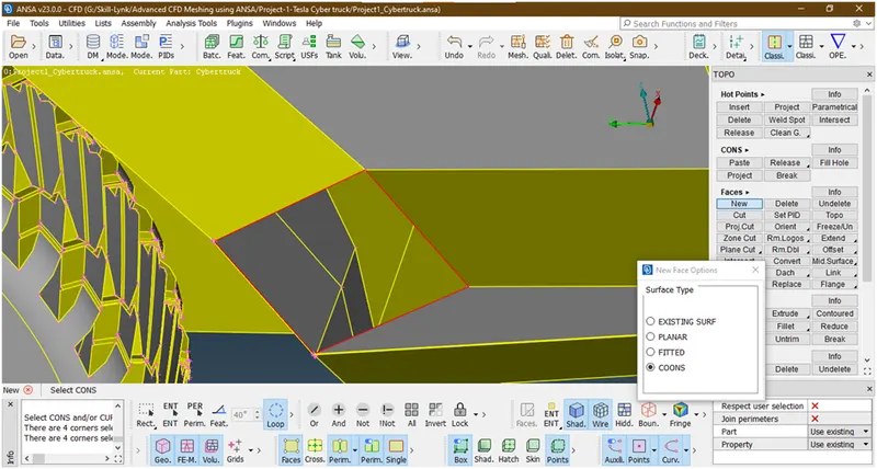
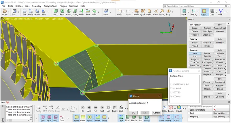
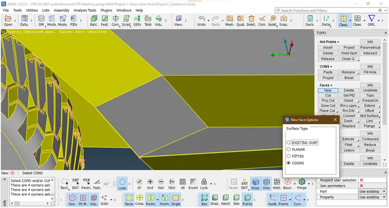
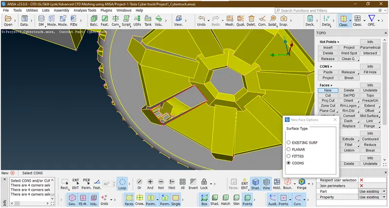
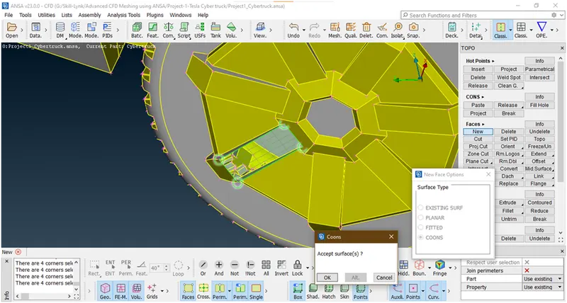
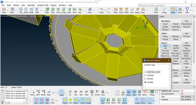
Similarly we are filling all hole.
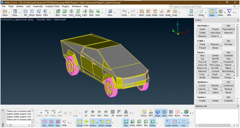
Now we have done .
- Lets change the resolution.for that goto classic mesh -> perimeter-> length
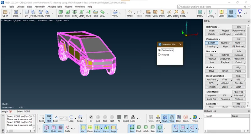
Now select perimeter and box selection and hit the middle click
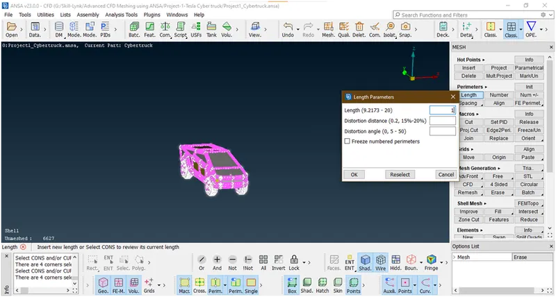
Then give length=1 and click on ok.
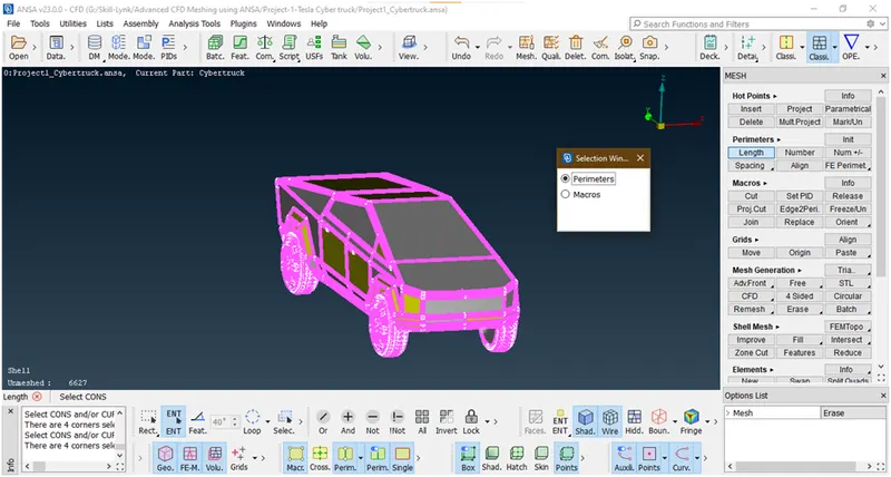
Now it has been change .now again goto topo mode
- Lets go for check errors.for that goto check-> check-> manager
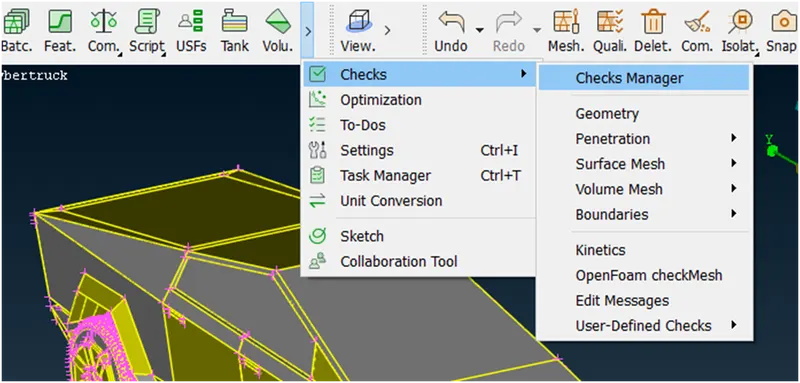
A new window opens
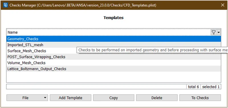
Double click on geometry checks again new window opens
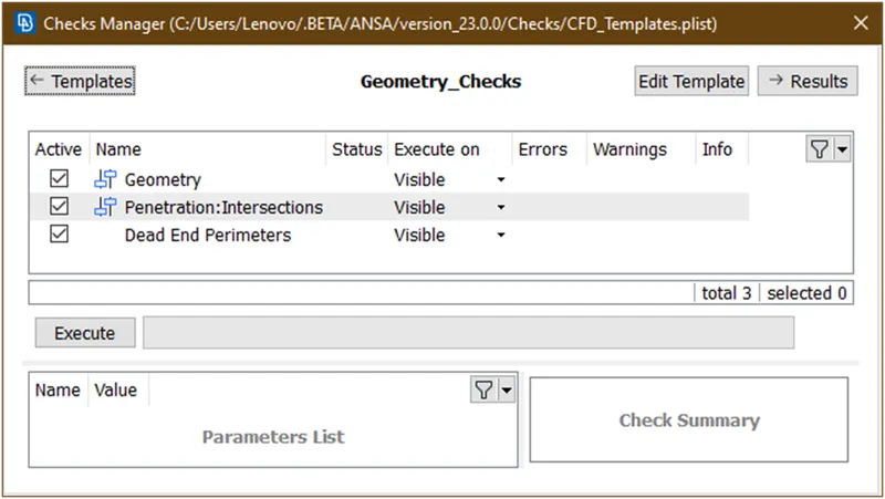
Click on execute.
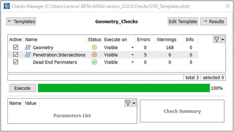
Lets see which are the warnings in geometry
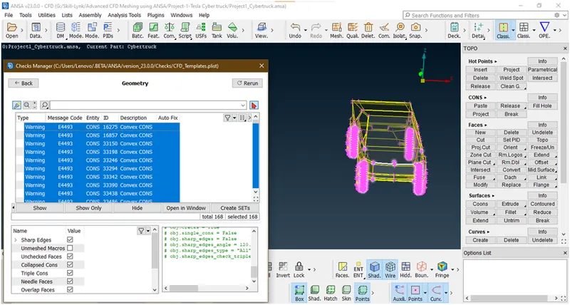
These are the convex,concave,mixed cons in tyres due to shape of tyres.right now we are ignoring.
Lets see what are the intersection error and where they occurs
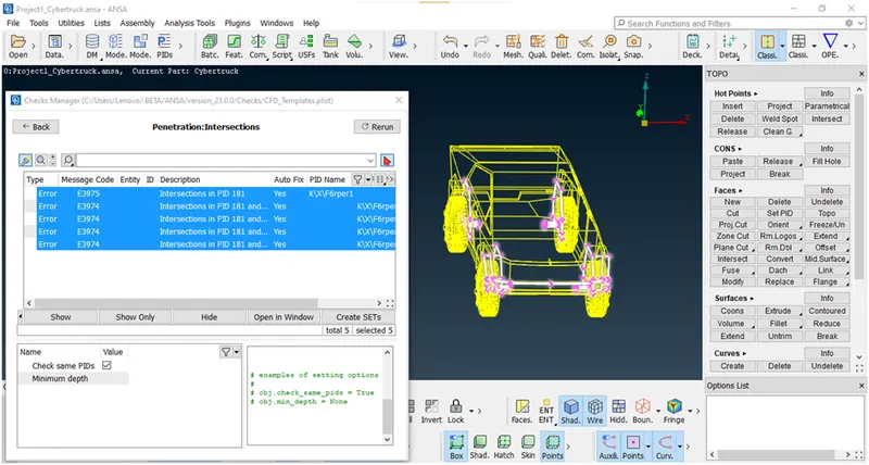
These are comes in tyres lets try to clear them.
- Let see why intersection error occurred in tyres.
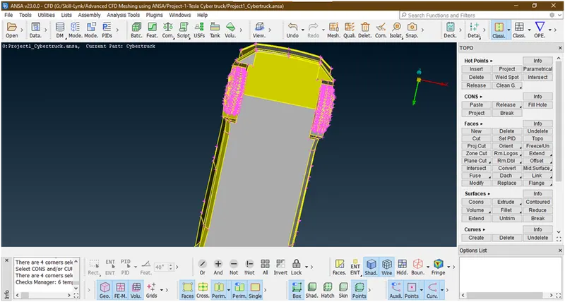
Let hide floor surface and see
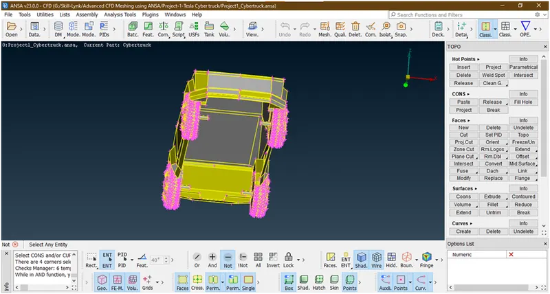
We hided floor surface let see in 1st tyre
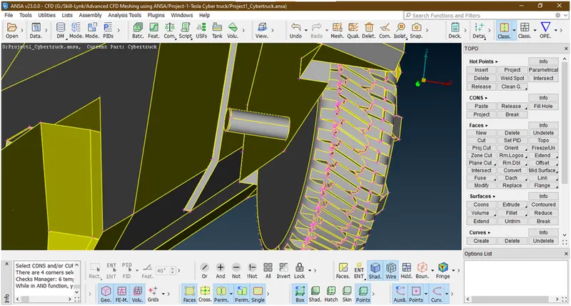
Now this is entity mode lets convert into pid mode and see.to goto the pid mode press ‘alt + v’.
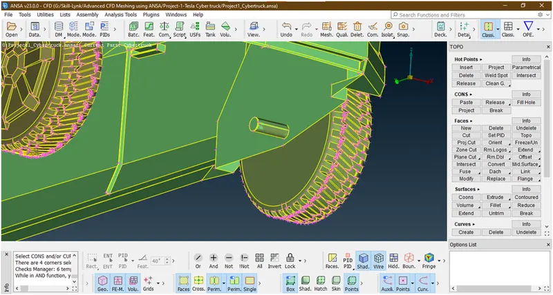
Now this is in pid mode.
Let hide this guard and see
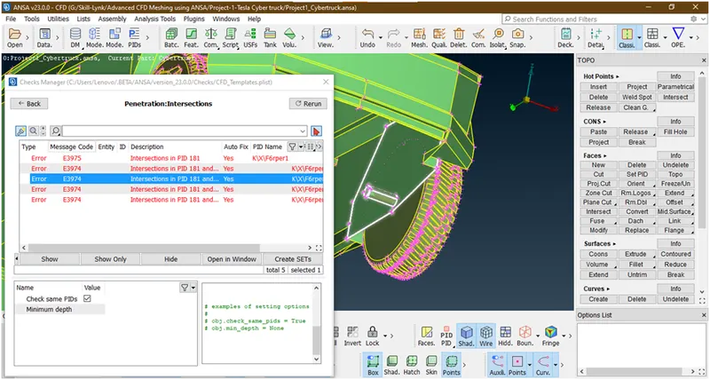
This guard goes into shaft
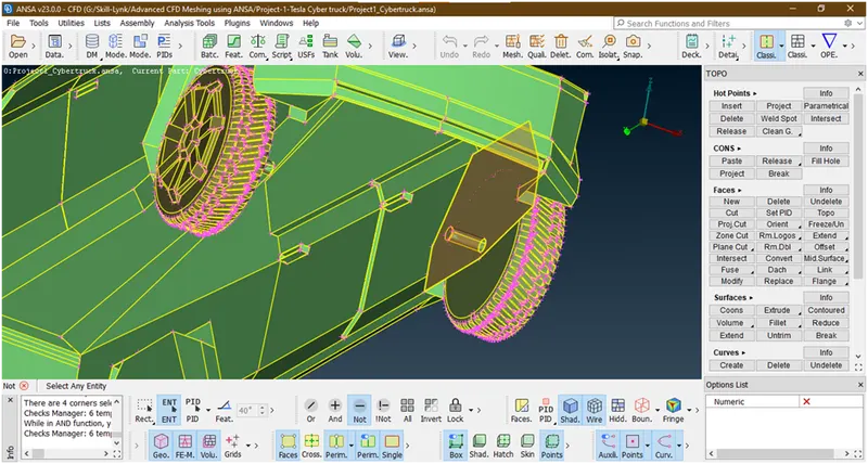
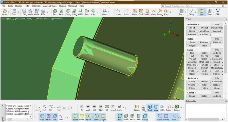
Lets try to delete this shaft and see
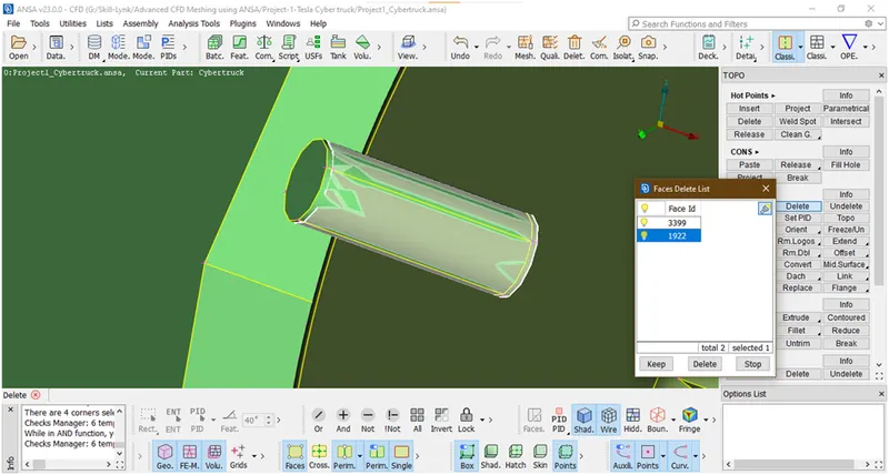
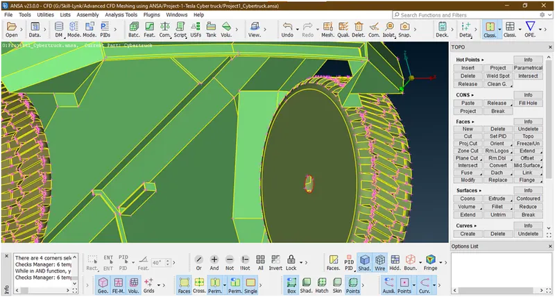
Now there is single con comes. Lets try to fill this by fill hole tool
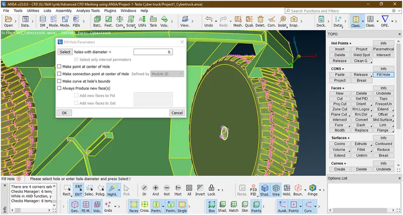
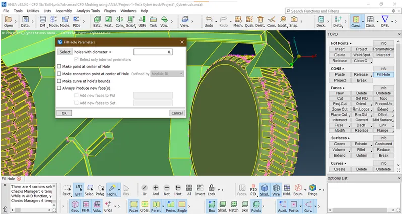
Lets enabaling guard for that click on all
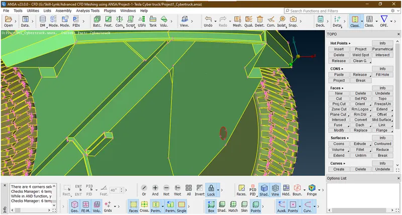
Let try to fill this hole
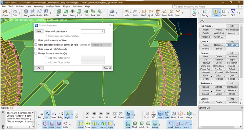
We have filled. Lets try ro check again error occurred or not
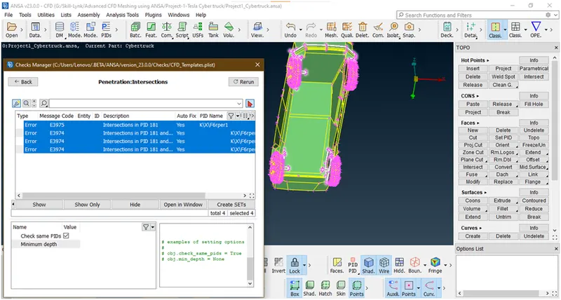
It has been removed .now by observing this we are getting point that in all tyres same intersection error occurred. So lets try to remove these errors by similar method.
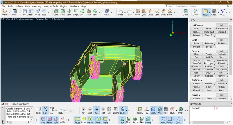
We have removed. now lets check for errors
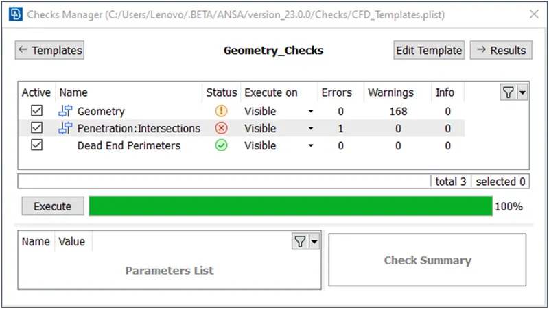
Now its removed let see where this single intersection error occurred.
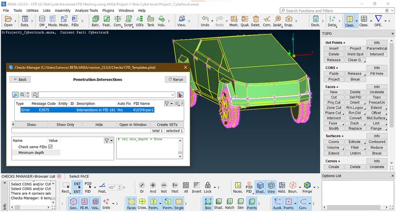
Lets clear this.
- Lets again goes to entity mode.for that press ’alt + shift + v’.
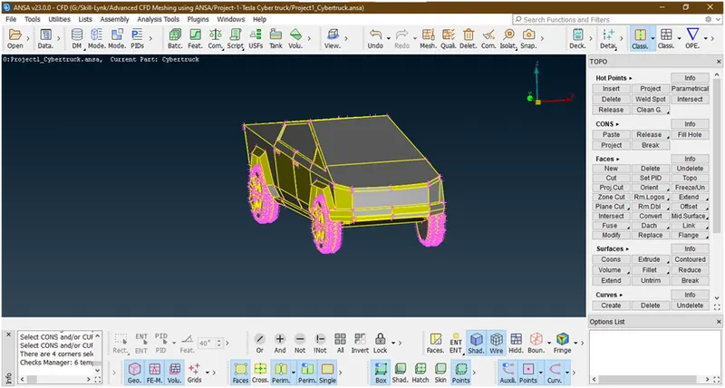
Now we are in entity mode.lets see why this error occurred in corners
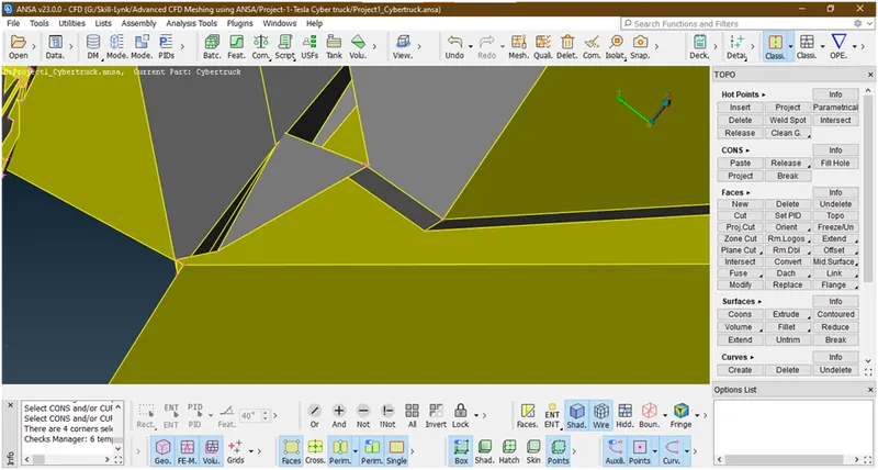
This is because of this lets try to delete this face
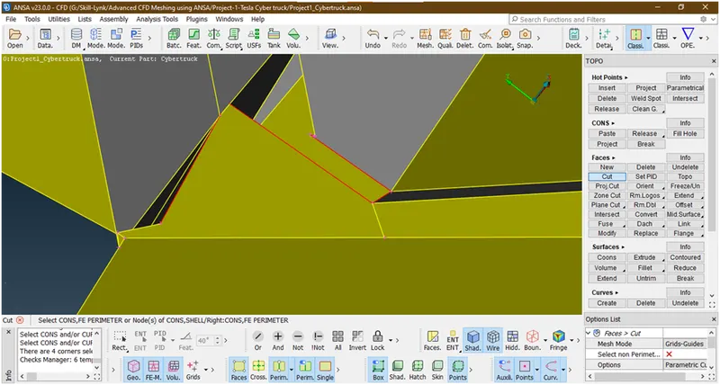
We have deleted again these some faces are there which causes error lets delete this
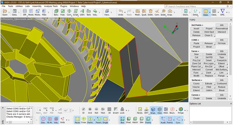
We have deleted lets try to make new surfaces there and see again error occurred or not

Now let check errors
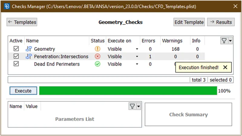
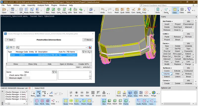
Now its from this side. Similarly we are doing for other side also
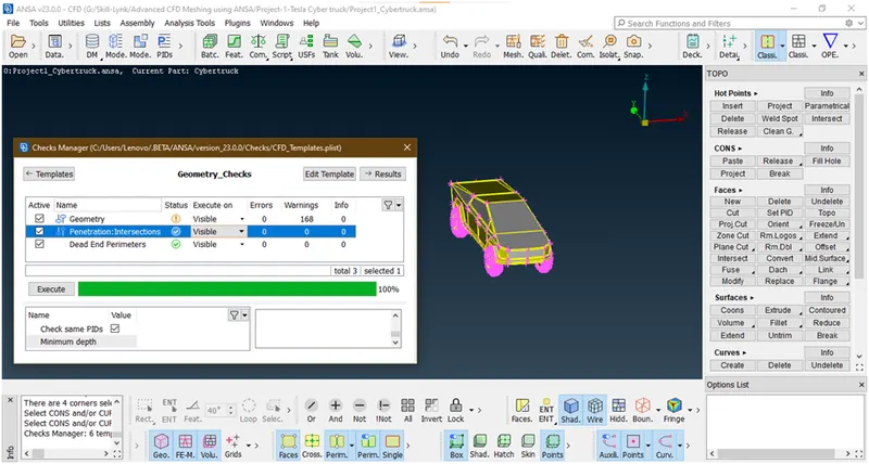
Now we have clear all errors. And the warnings are concave and convex cons due to shape of car so we are ignoring .
- First we are hiding some faces
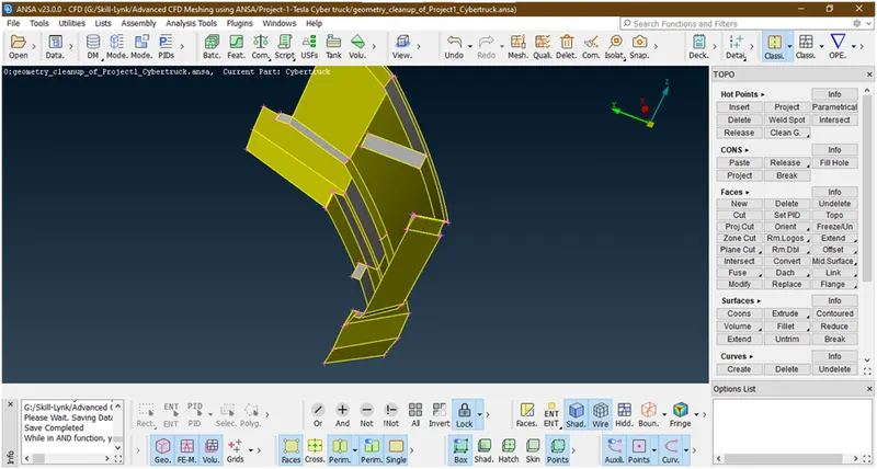
We have hid the some faces. lets try to delete these internal faces .after that some red cons created there we are creating surfaces. these are we are doing because we are going for external flow analysis and these extra internal surfaces create extra volume.
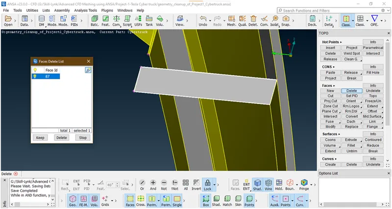
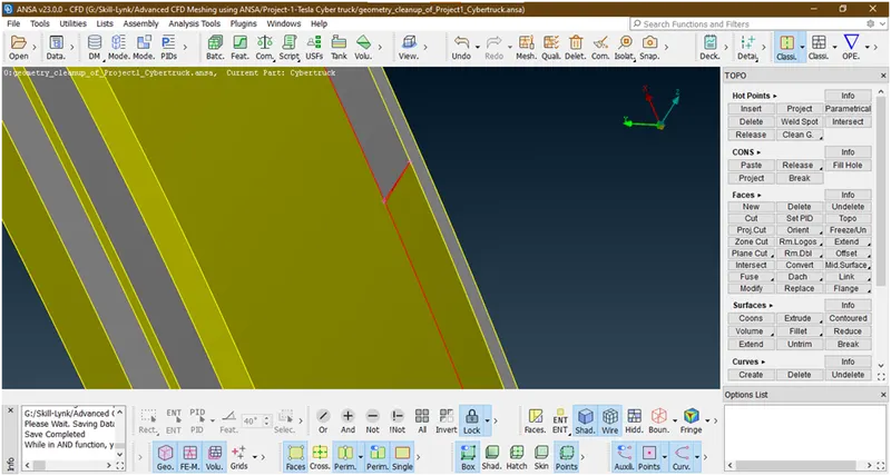
We have deleted.due to this some red cons are created
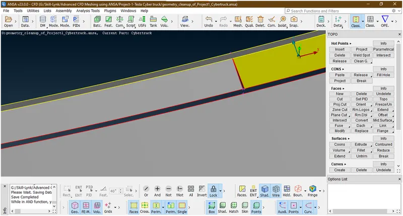
So let make a new face there.
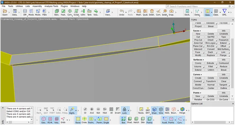
We have created. similarly we are doing for next one.
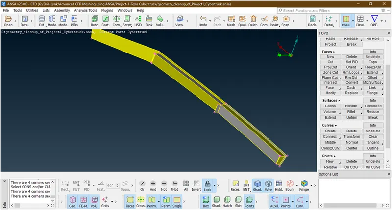
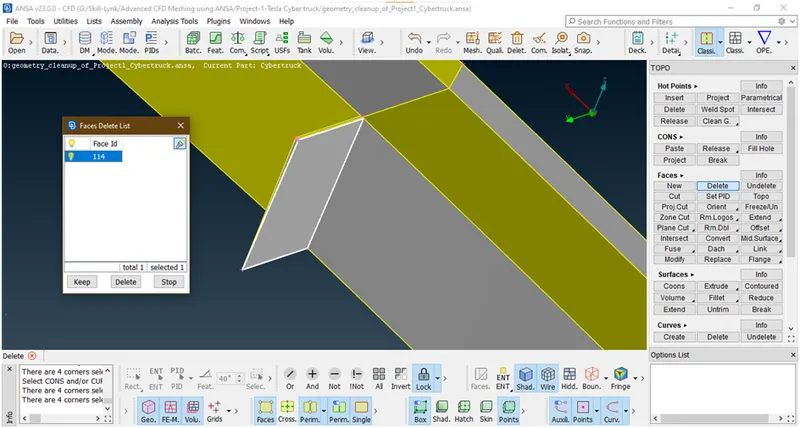
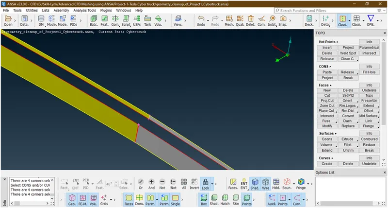
Now lets create a face there
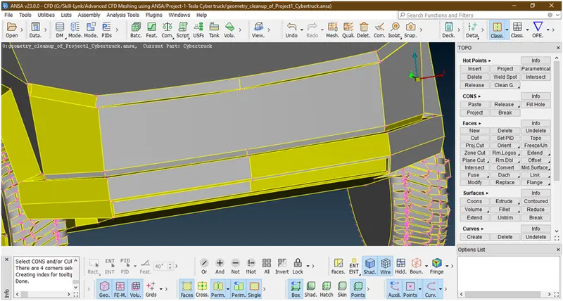
we have successfully created face.now click on all to show all components.
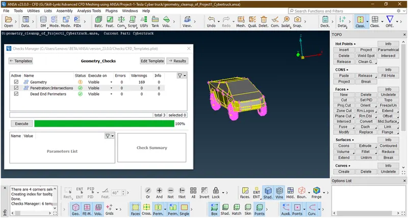
Lets again check for any errors
Let see warnings
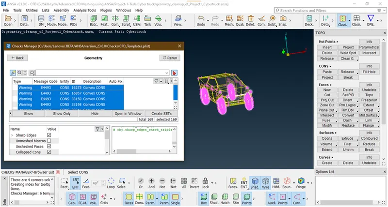
These are all conevex,concave cons in tyres due to shape so we are ignoring.
- Let delete extra hotpoints.
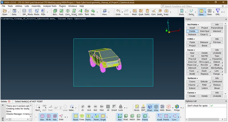

Its done.
- Lets assign pids.
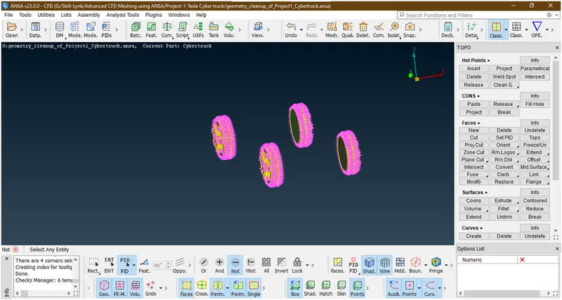
- Lets assign tyres:
Firstly hide other parts
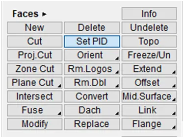
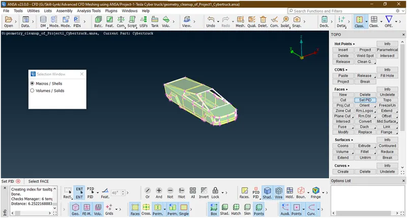
Goto faces->set pid
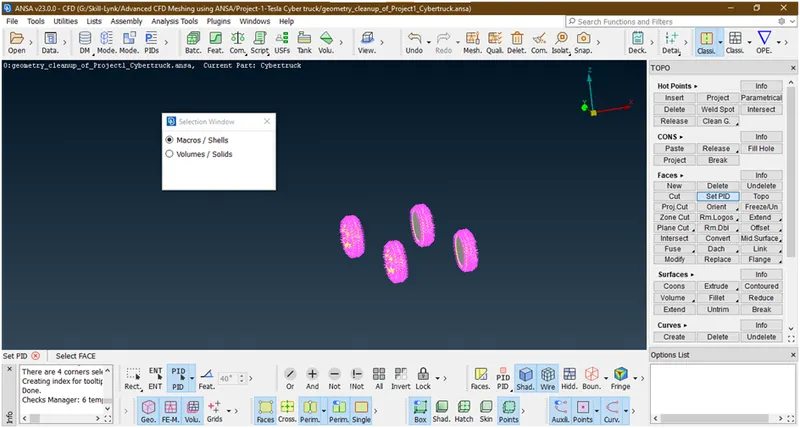
Then a new popup opens Select macros and Select tyres by using box selection
Hit the middle key
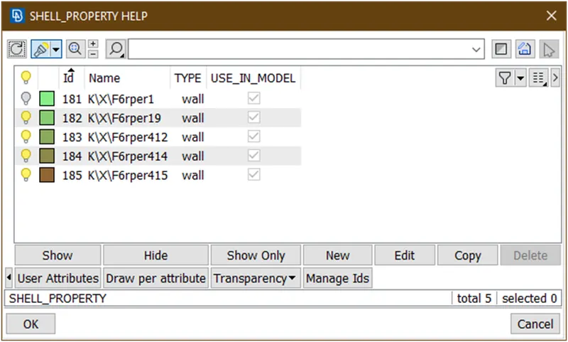
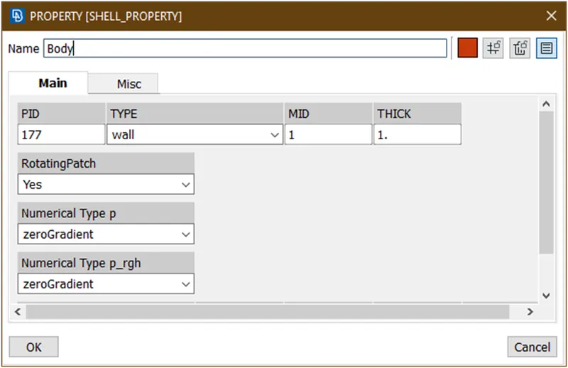
Click on new
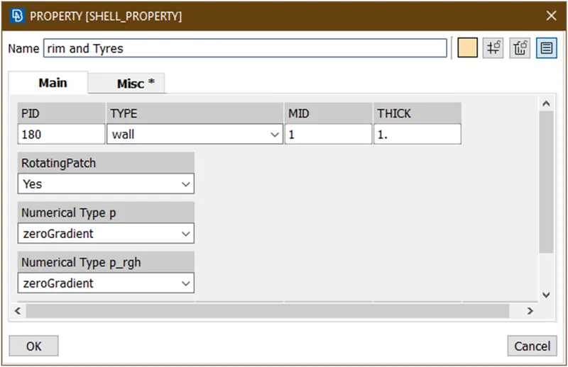
Give name as shown above and click on ok
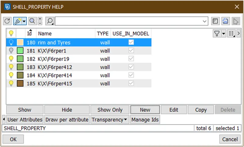
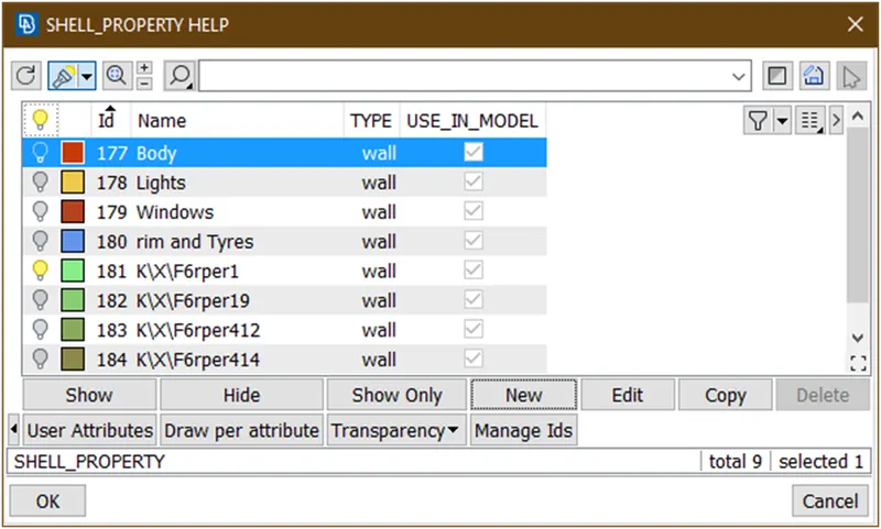
Now it has been created.to assign double click on it.
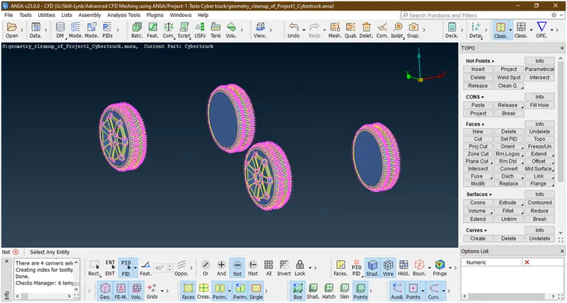
It has been assign.
- Let assign windows :
Follow similar procedure as describe above
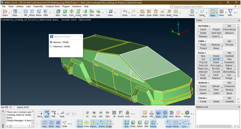
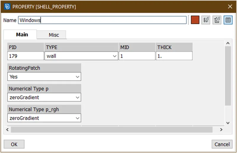
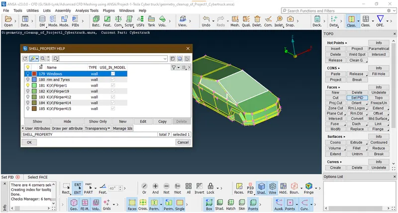
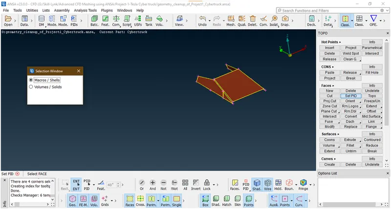
- Lets assign lights :
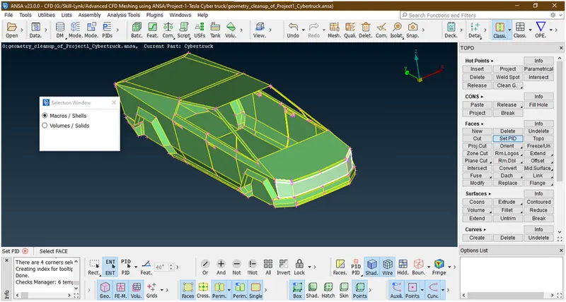
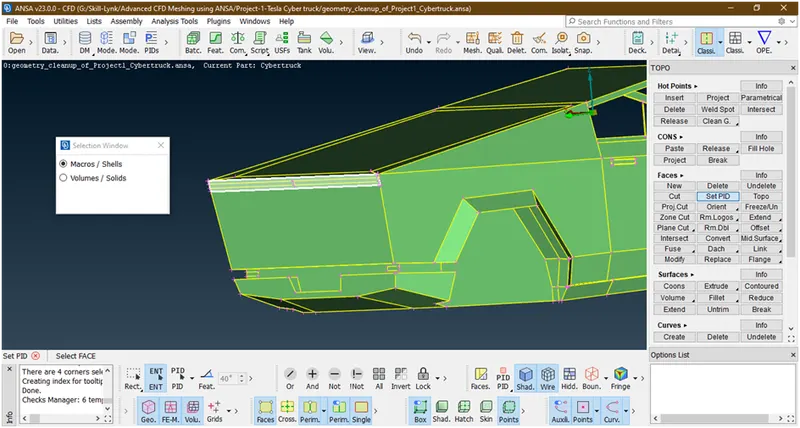
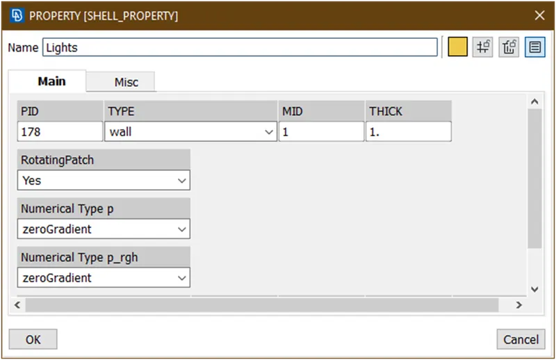
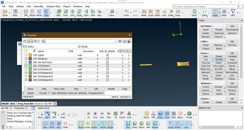
- Let assign body :
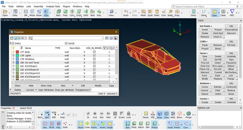
All has been assign let cross check.
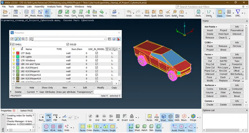
Now remove unnecessary pids by using compress tool.
Now click on compress

A new popup opens
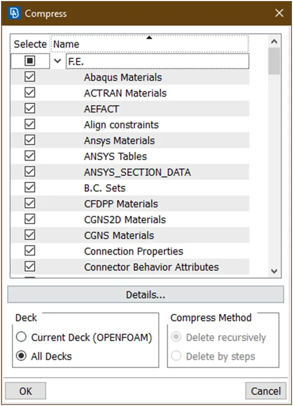
Now click on ok
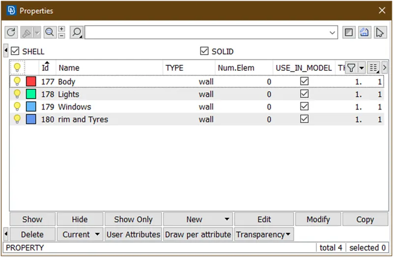
Its done. We have assign all pids. now we are going for surface meshing.
3. Surface meshing :
- Goto classic mesh
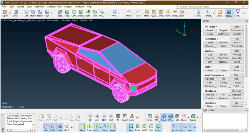
- Lets give universal quality criteria.lets goto quality parameter

A new popup opens
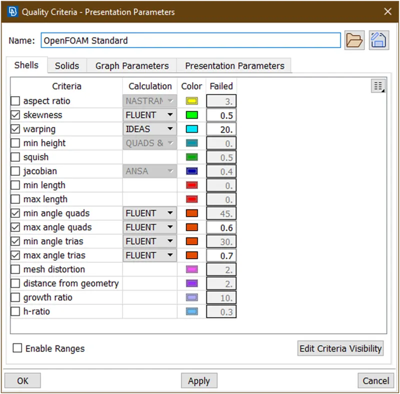
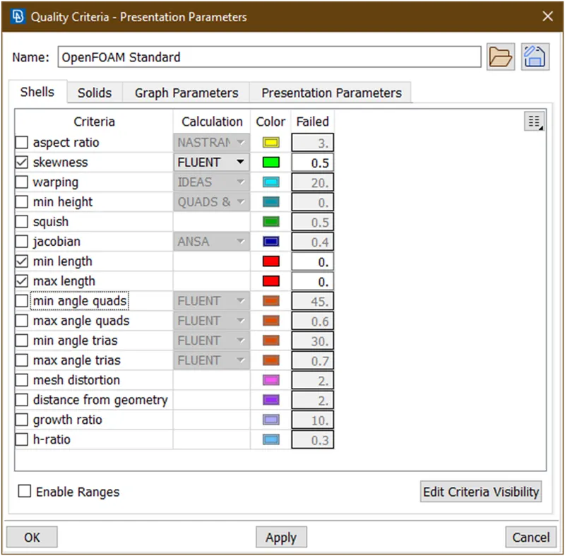
Just enabled skewness,min length,max length.
Now goto the edit criteria visibility.
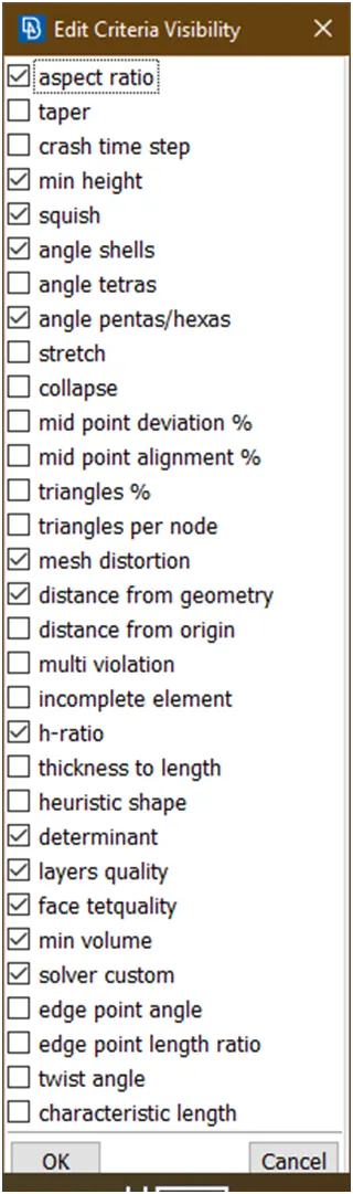
Switch off all and click on ok.
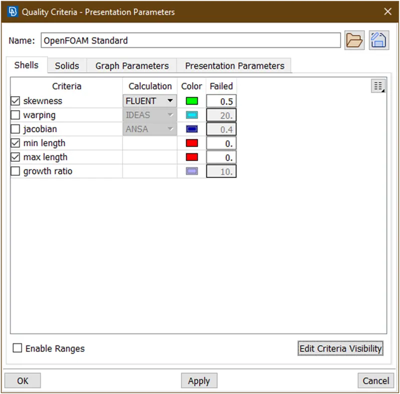
Now gives values. Here skewness=0.5,min length=1,max length=6 because here the minimum target length = 2mm and maximum target length=4mm
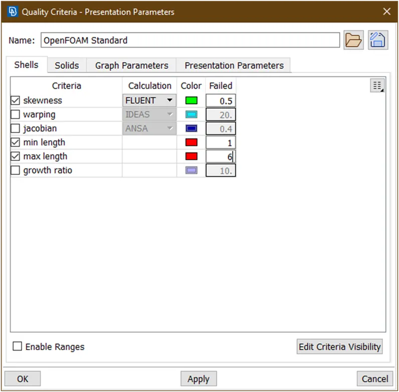
Now click on apply and then click on ok.
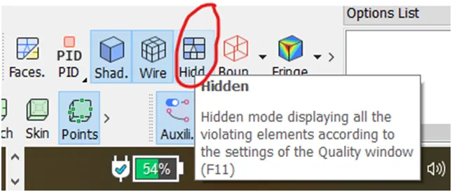
Now click on hidden
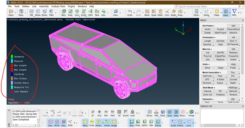
now click on this parameters which we don’t want
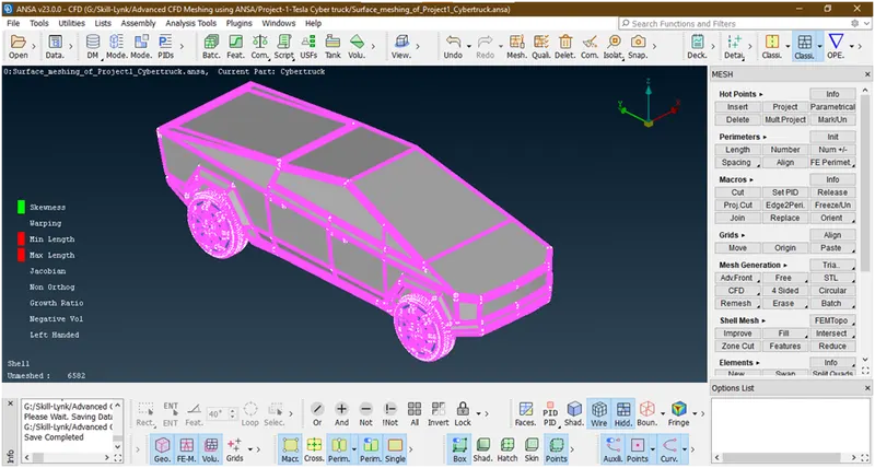
Now right click on this inactive parameters.
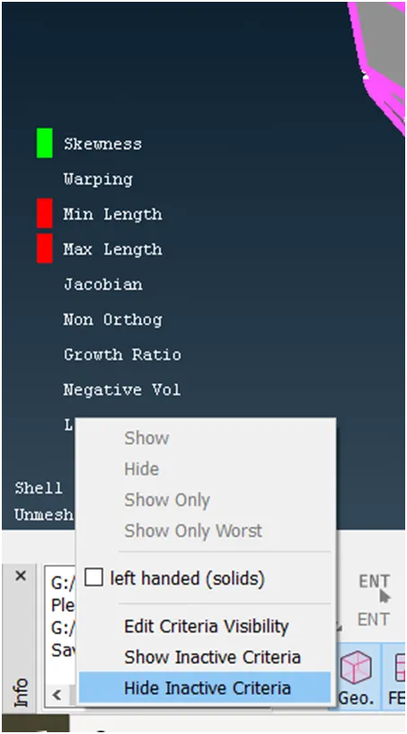
Now click on highlighted part.
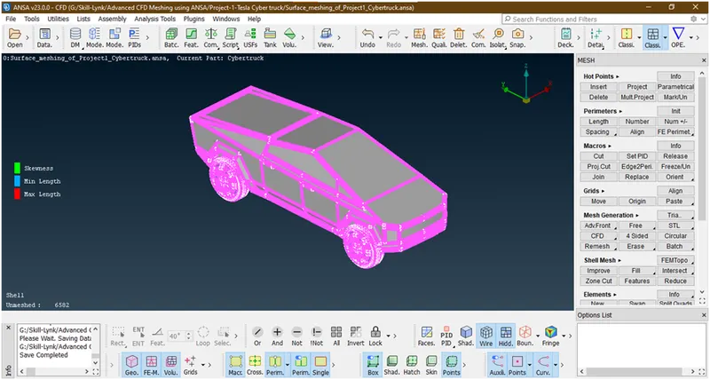
Now its done. Now we are going to mesh one by one parts.
- Lets mesh tyres as target length=2 for both.
Let hide other componenets.for that goto pid manager
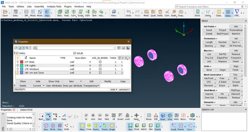
Switch off all other bulbs
Now goto the mesh parameter
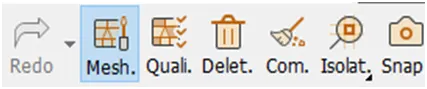
A new popup opens
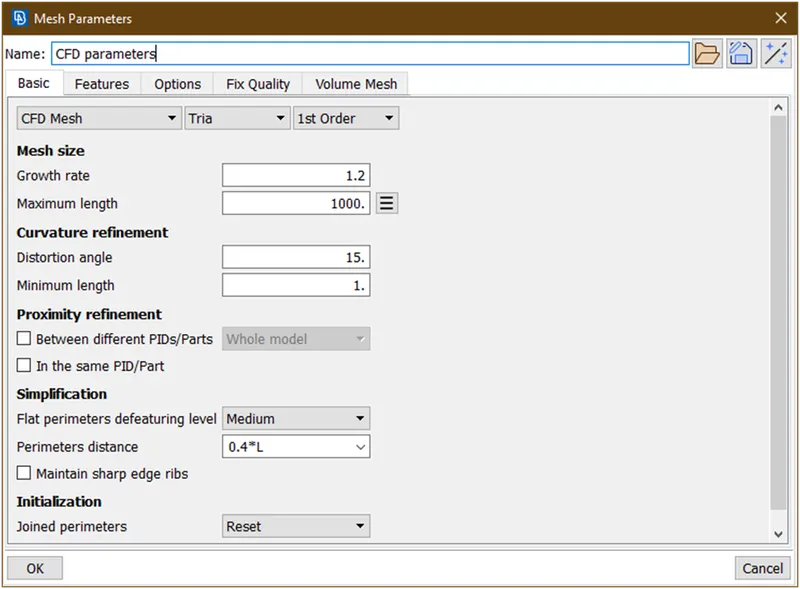
We are giving min length=1.5 and max length=2.5 as target length=2
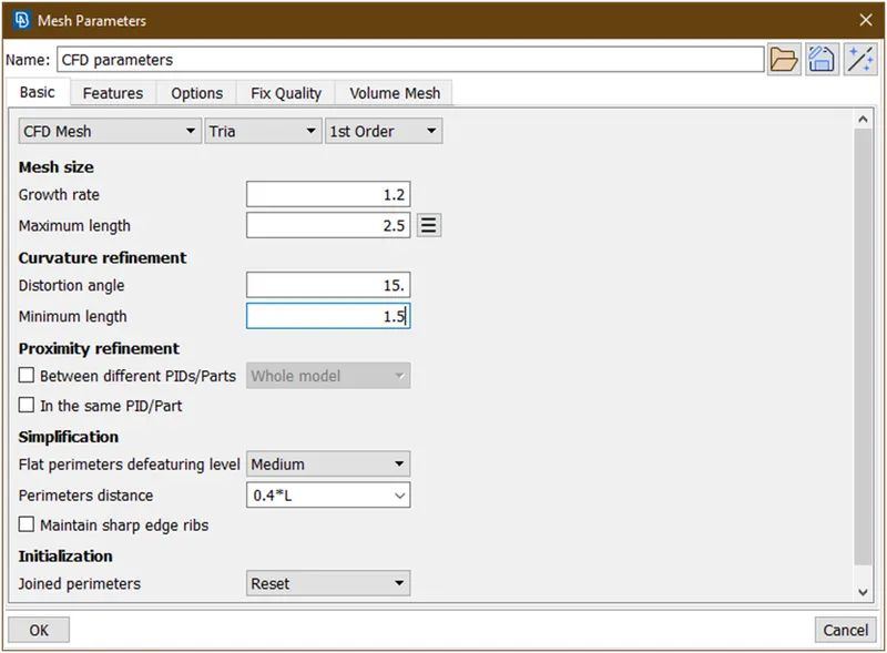
Now click on ok.
To give target length goto perimeter->length
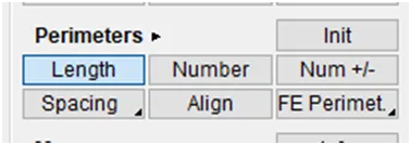
Then new popup opens select perimeter and box select the parts
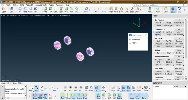
Hit the middle click,then new popup opens
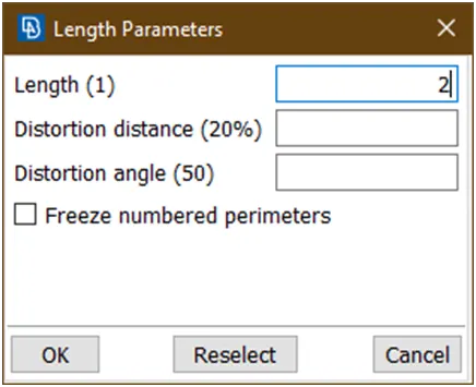
Then give length=2 and click on ok. after this select macros
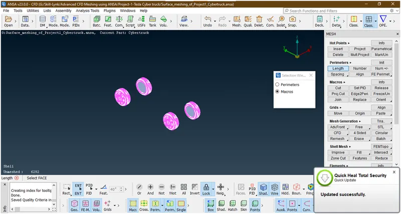
Again hit middle click
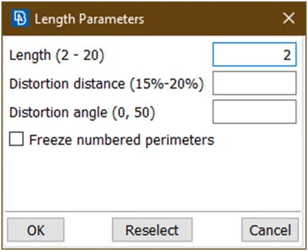
Again give length=2 and click on ok. after done we are going for mesh.
Now goto mesh generation -> cfd -> visible and wait until done
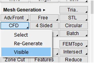
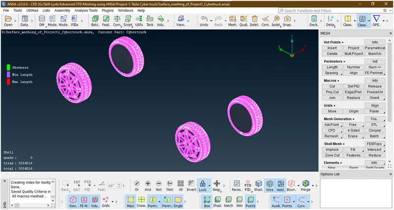
Now its done.
here there is no off elements. Now let freeze this mesh.for that goto macros->freeze/un -> box selection by left key to freez.
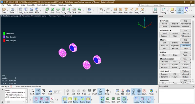
Now its done.
- Lets mesh windows.
Goto pid manager and enabled windows
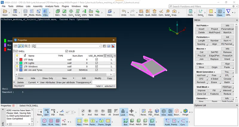
Here target length=2 so min length=1.5 ,max length=2.5
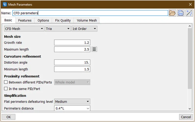
Click on ok.now goto perimeter -> length and give target length=2 as explained above.Now goto mesh generation -> cfd mesh -> visible and wait until mesh tobe done.
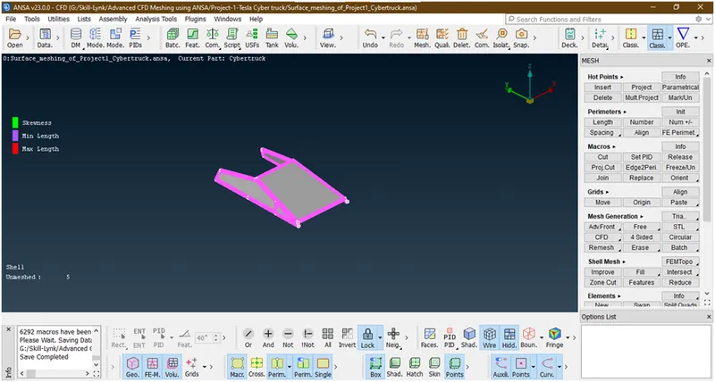
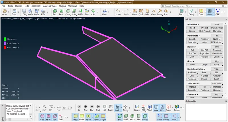
Here 8 elements are off lets try to improve. Just right click on off and goto improve
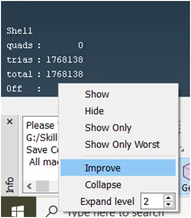

Here 4 options are coming reconstruct, reshape , smooth and fix quality choose any of them 1 by 1 and click on this ‘->’
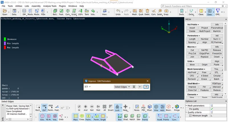
Again click on this ’->’
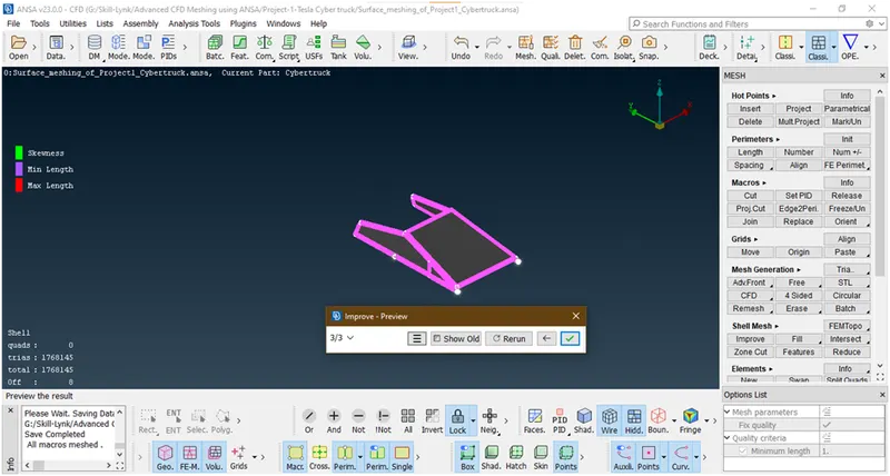
Now click on right button and repeat this process until off elements=0
These are not removed so lets try to move grids and try to fix manual. For that goto grids -> move -> and slelect node
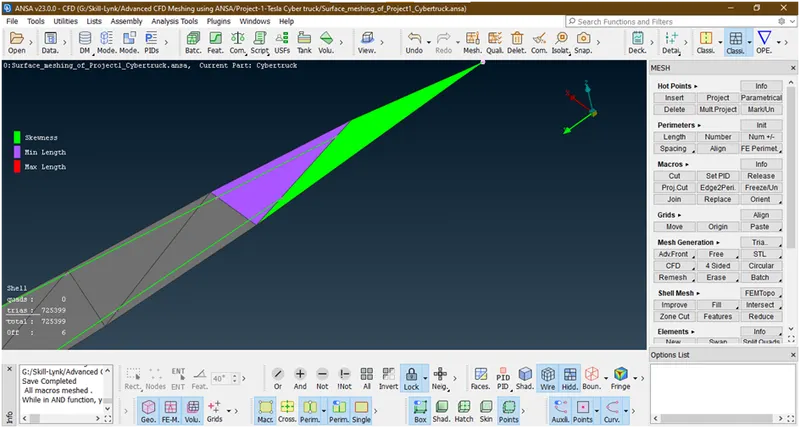
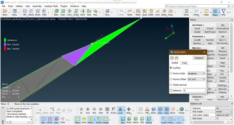
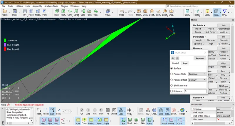
Similarly we will try to settle this skewed triangle
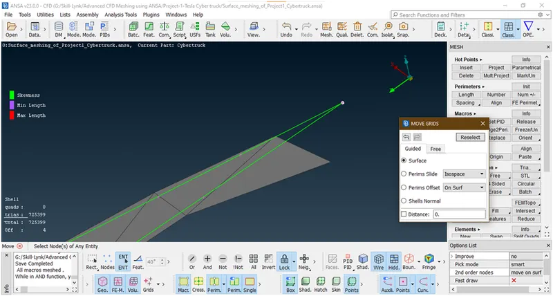
Now lets see another one.
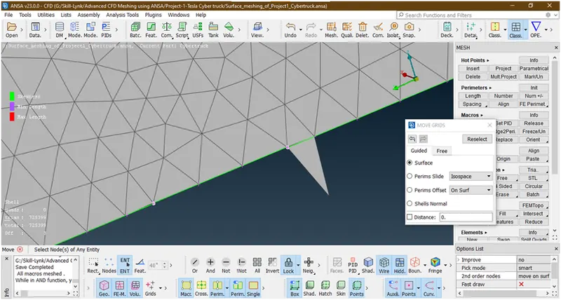
Similarly I am checking.

Now we have removed all off elements.lets try to freeze them by similar procedure.
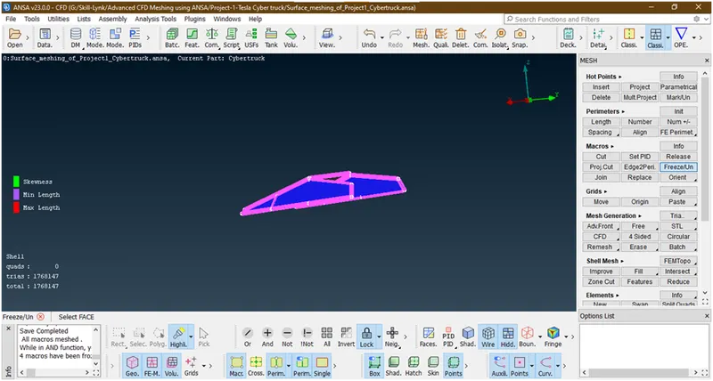
Its done.
- Let mesh lights.
Enabeled lights.
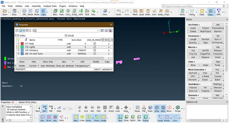
Now lock the geometry.here target length=4. So min length=3.5 , max length=4.5
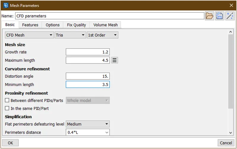
Now goto perimeter -> length ->first select perimeter and box selection of geometry then select macros and box selection and give target length =4
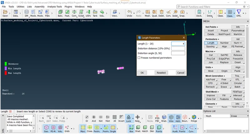
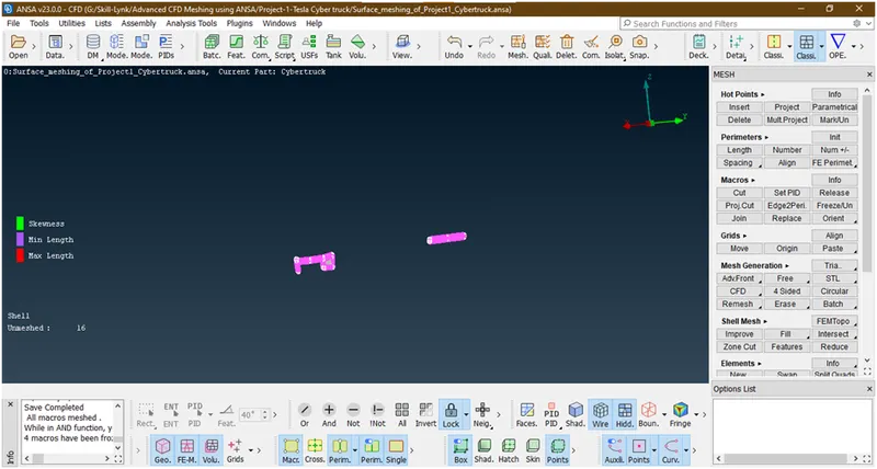
Now goto mesh generation -> cfd -> visible
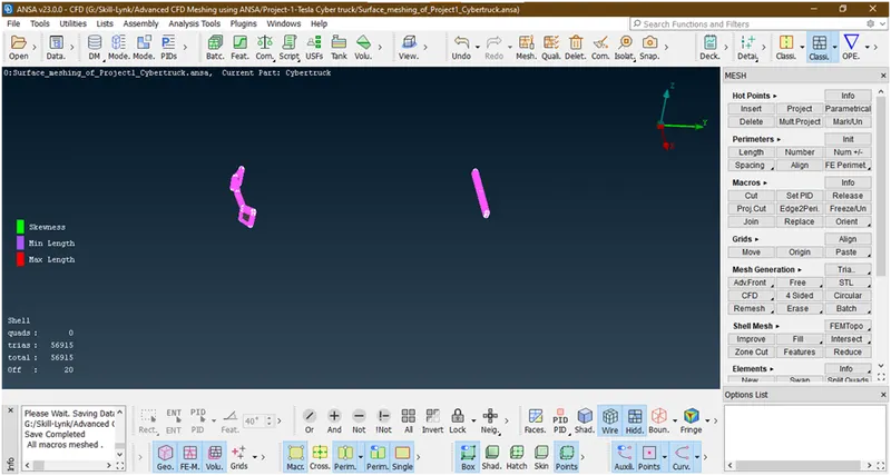
Here 20 elements are off lets try to improve by similar method.We have done. Lets freeze this.
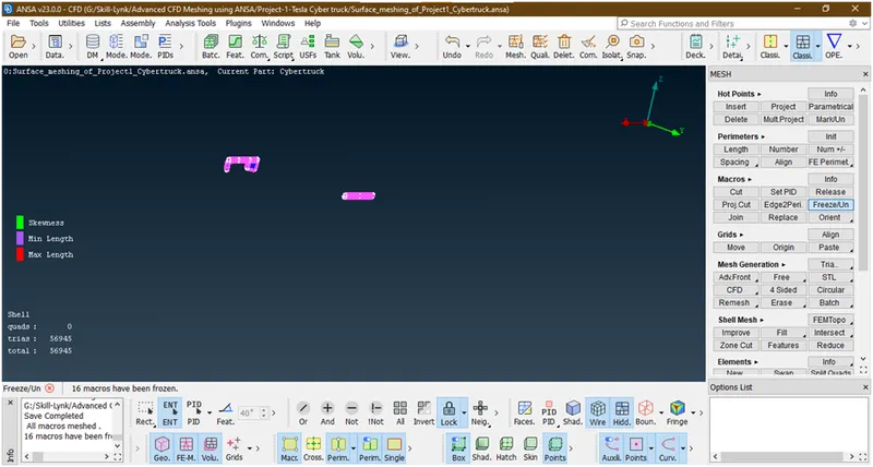
The off elements are removed.
- Let mesh body .
Goto pid manager and Enable body
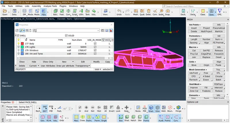
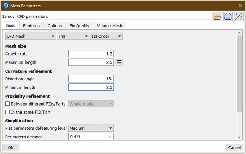
Here the target length=3 . so min length=2.5 and max length=3.5.
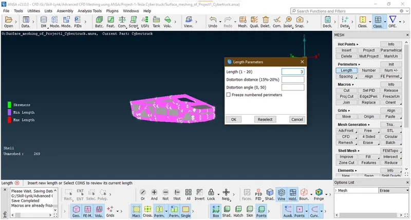
Now goto length and give target length=3
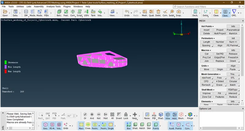
Now goto mesh generation -> cfd mesh -> visible.
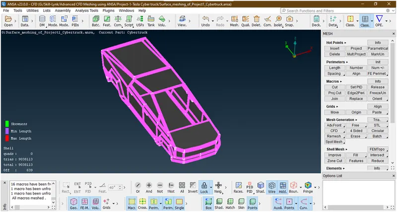
Now its done.here 639 elements are off lets try to improve and reduce the off elements.repeat the same procedure as explained untill off elements=0 and if they are increasing then stop this.
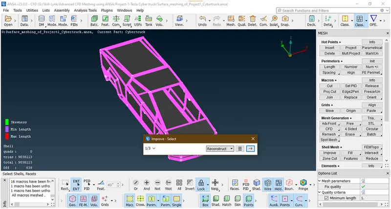
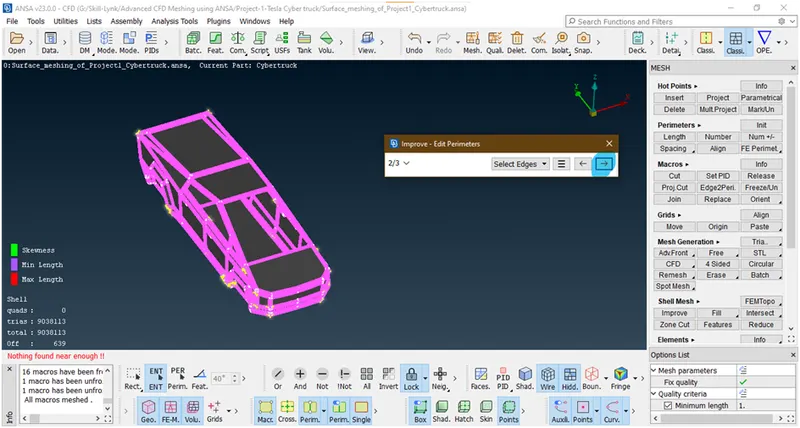
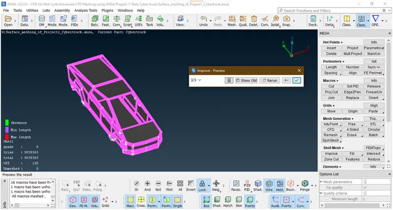
Click on done
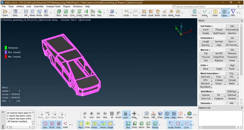
repeat the procedure. By changing options till off =0
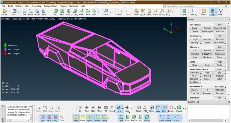
Now its done.let freeze this macros
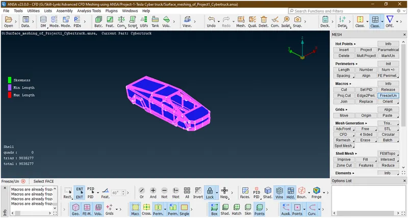
Now its done .let Crosse check each and then click on all.
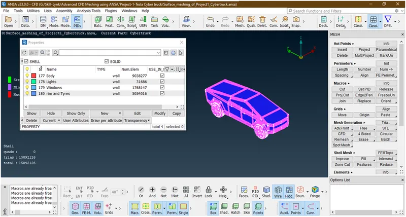
We have succefully created a cfd surface meshing of tesla cyber truck. Now we will go for volume meshing. Now here we are doing an external flow analysis. for that we need a wind tunnel and do analysis in this wind tunnel. so lets go for crating and surface meshing of wind tunnel.
4. Creating wind Tunnel :
- Goto topo mode.
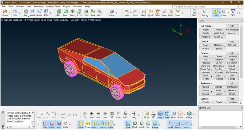
Here the wind tunnel is closed volume entity like room which is used for simulate the external flow analysis of air over a car.
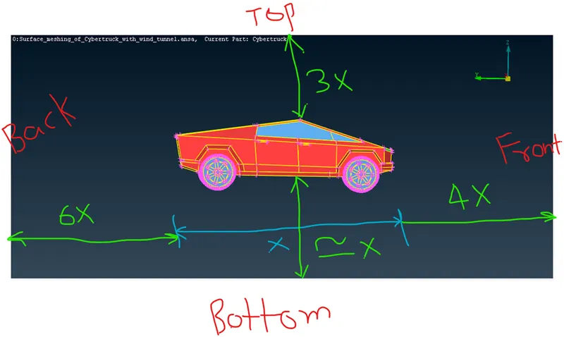
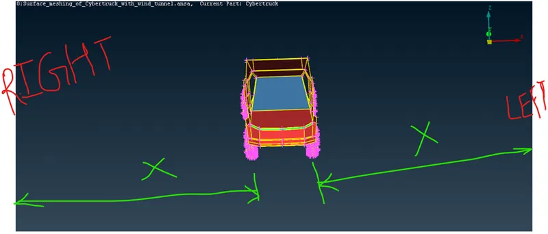
- Let,
Length of car = x
Front face at= 4x
Back face at = 6x
Top face at=3x
Bottom face = at convenient position that should not be intersect to the car
Left,right faces at = x
As shown in figure
Lets start to create a surfaces
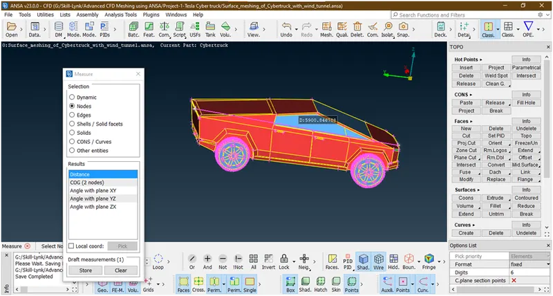
Let the distance of car=x=5900
- Let insert a point at middle from bottom side.for that goto relative under points.
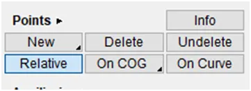
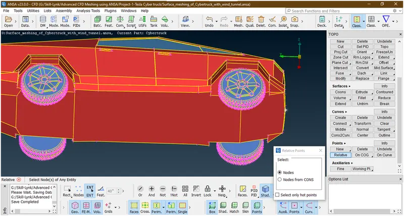
Now hit the middle key
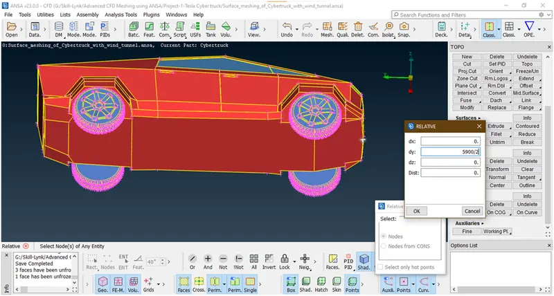
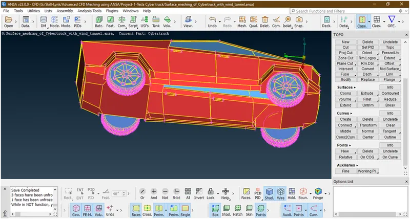
- Now creates a points by taking reference of this point at a distance which mentioned above.
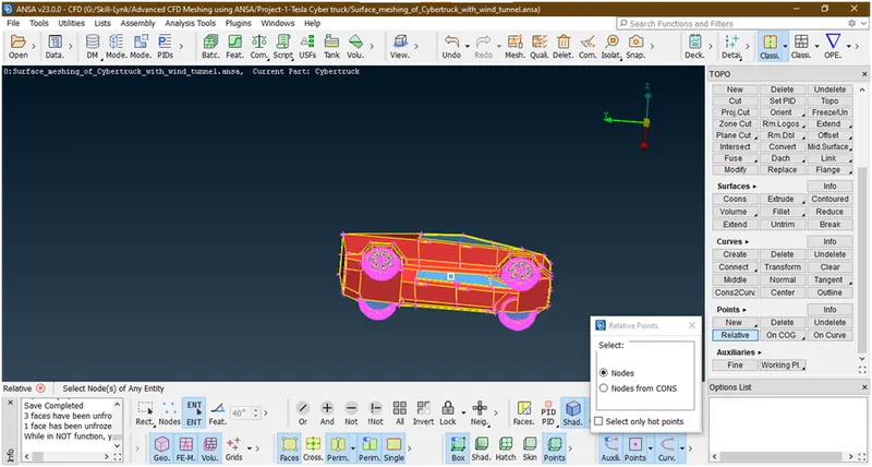
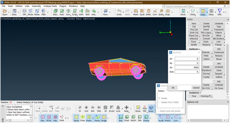
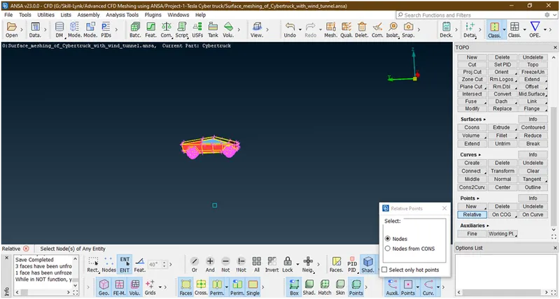
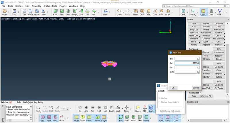
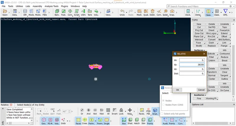
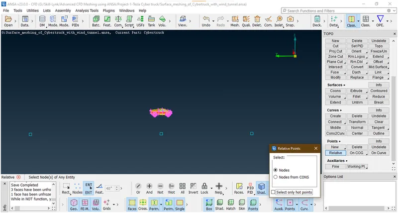
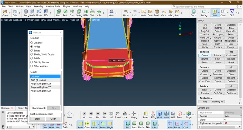
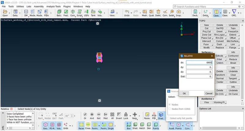
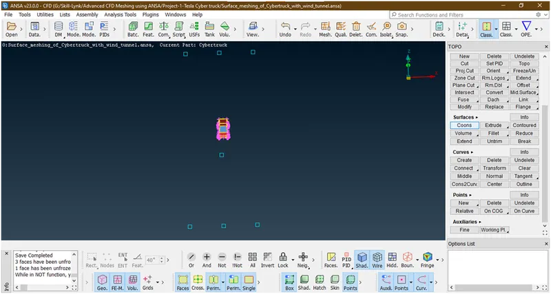
Now we have created all side points.
- now create the curves between these points for thatGoto curves->create-> select the points
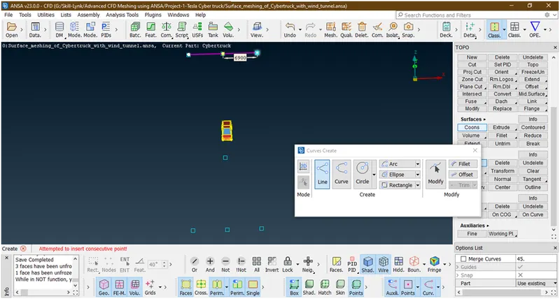
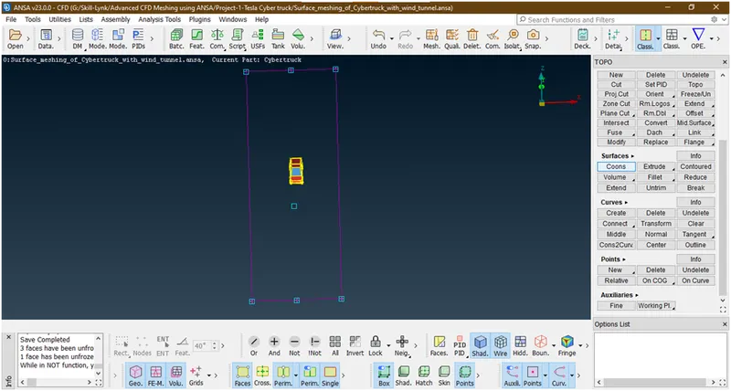
- Now create a surface between these curves and set the pids.
- Bottom SURFACE :
Goto the faces->new-> select the curves
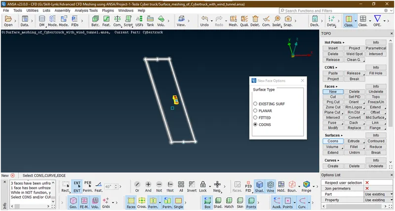
click middle key a new popup opens
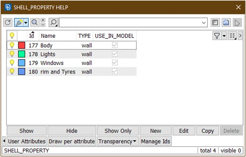
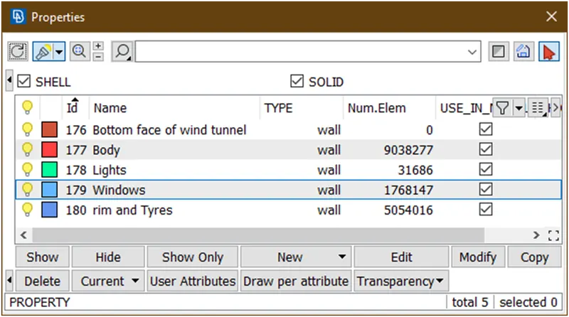
Click on new again new window open
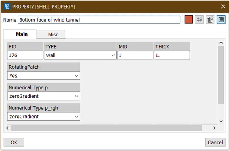
Give name as shown in figure and click on ok
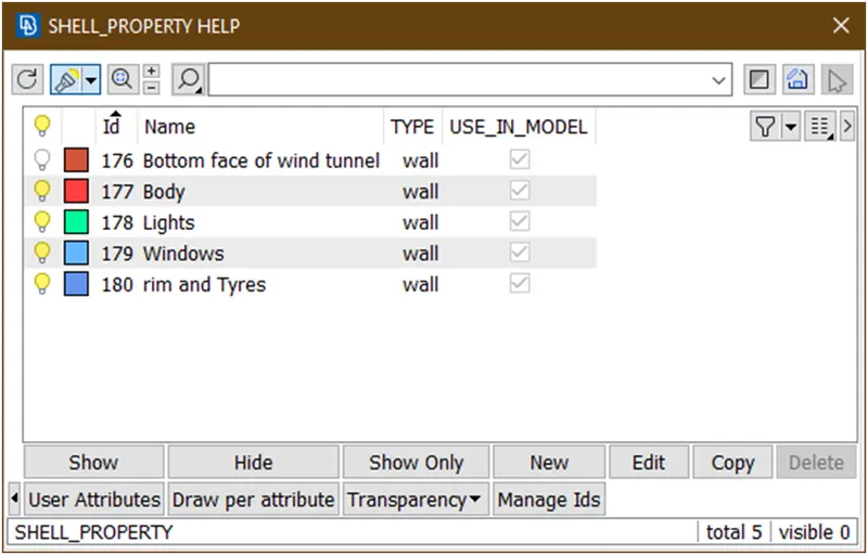
Double click on this
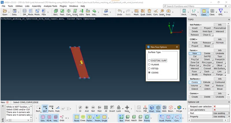
It is created.Similarly create all the faces.
- Top surface :
Now we can delete these points and curves.for that goto pid manager and hide all parts
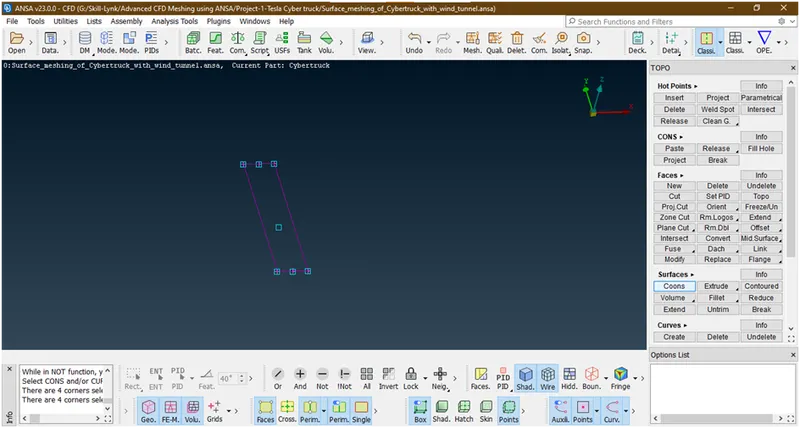
now delete all this by clicking on universal delete and then click on all
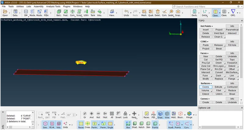
Now create a top surface by using offset tool under faces
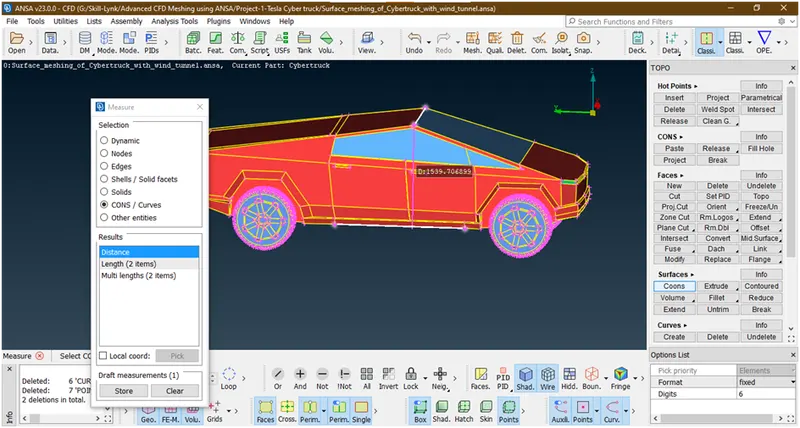
Let take distance= 5900 +1600+3*5900=25200
Now goto the offset under faces and select the face
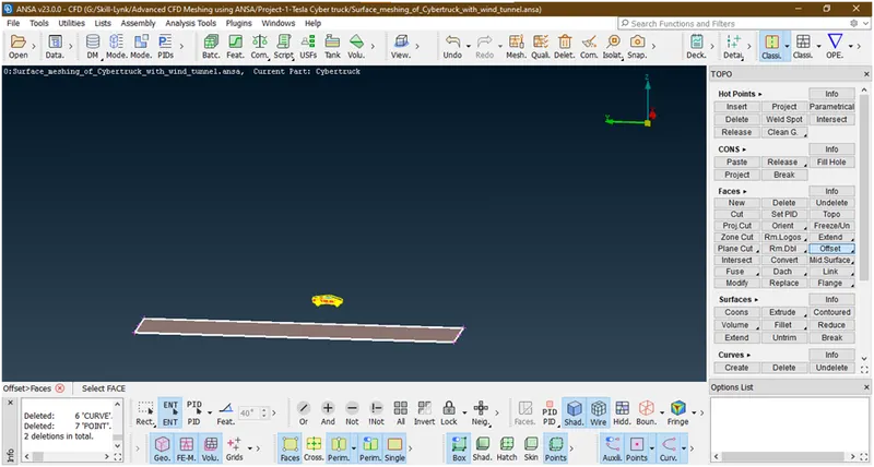
Hit the middle key
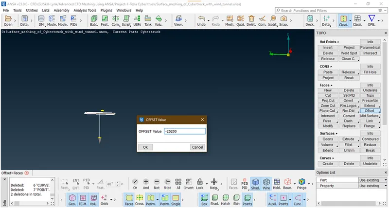
It is showing downward arrow but we want in opposite direction so use ‘-25200’ then click on ok.
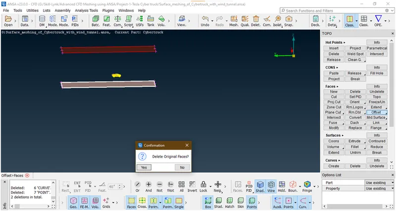
Click on no
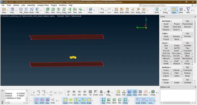
Now goto set pid under faces and select the face.
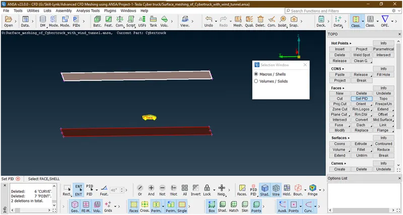
Now hit the middle key
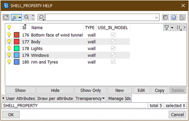
Now goto the new and create top surface of wind tunnel pid
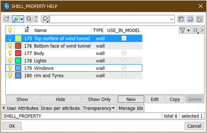
It created.to assign double click on this.
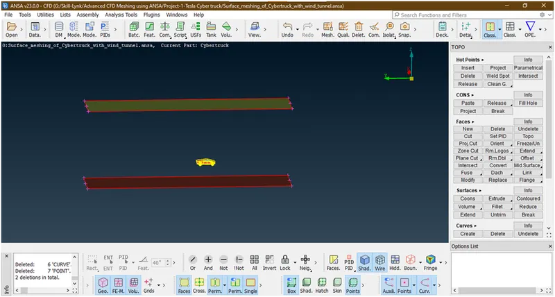
Now create the side faces
- All side faces :
For crating the faces follow same procedure
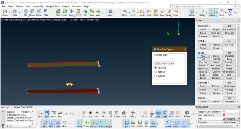
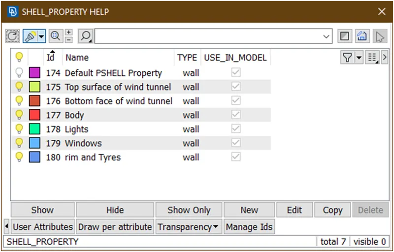
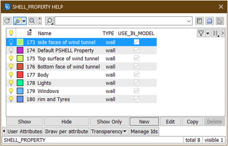
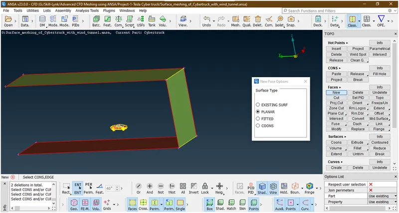
Now follow the similar procedure to create all faces and assign them in side faces.
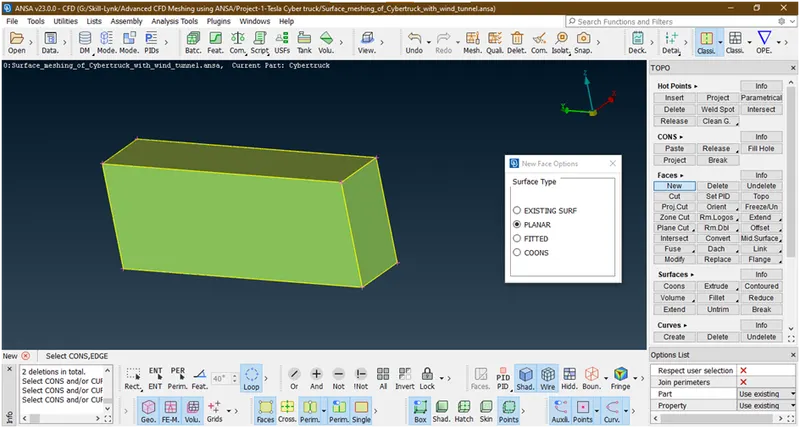
We have successfully created the surfaces.no we are going forward to mesh them.
- Let check for errors to be remained.
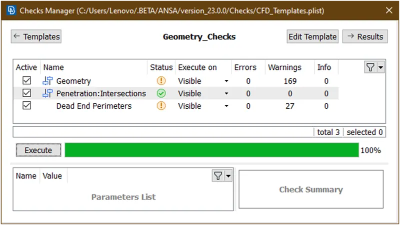
Let check warnings
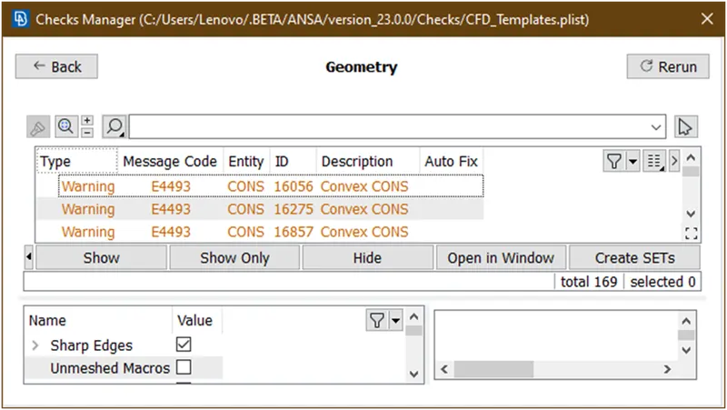
These are due to shapes so we are ignoring it.
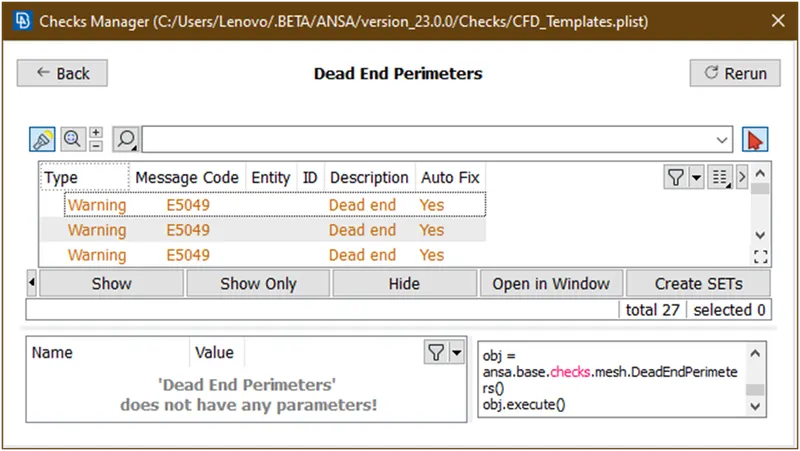
These are also ignorable..now lets go for mesh the the wind tunnel.
5. Surface meshing of a wind tunnel :
- Goto classic mesh
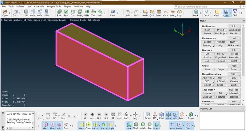
- Goto pid manager and and hide tesla cyber truck parts
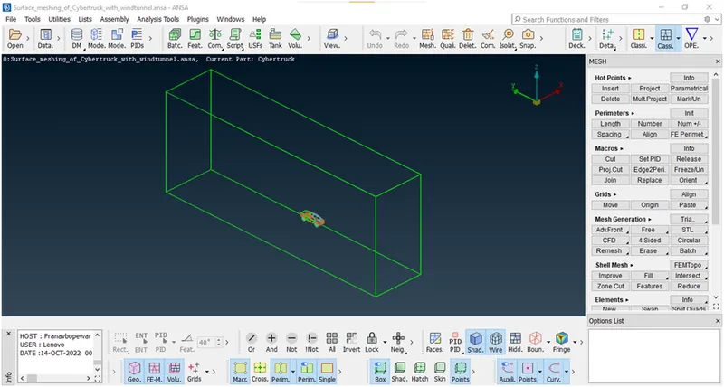
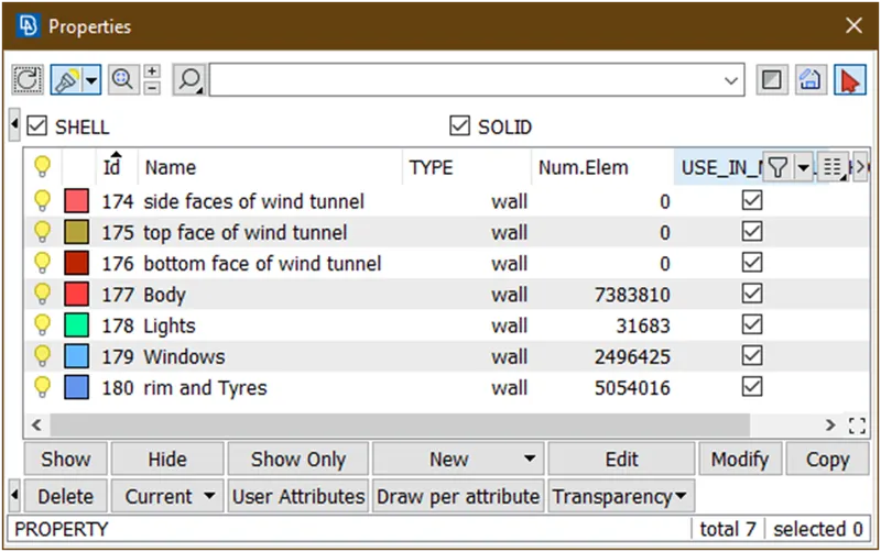
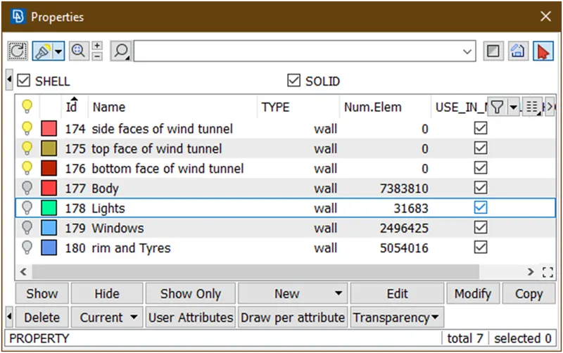
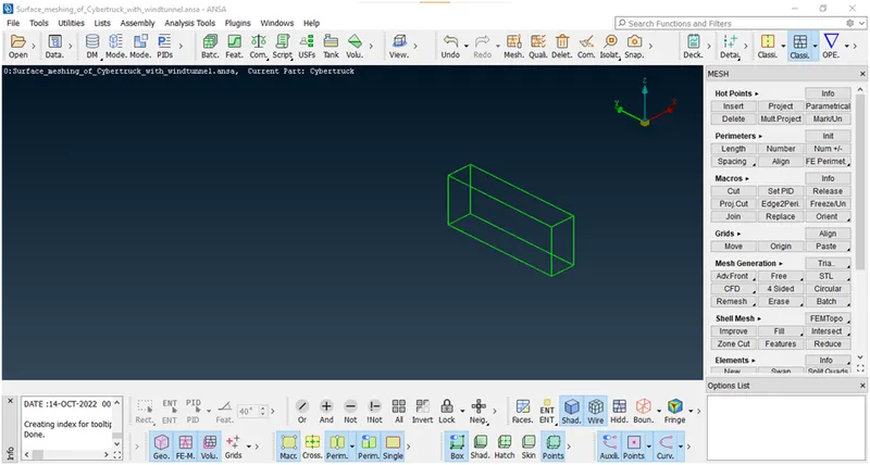
Its done.
- Let mesh bottom face with target length=100
Hide other faces
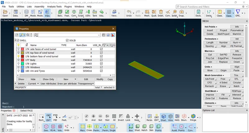
Goto mesh parameter and put min length=95,max length=105
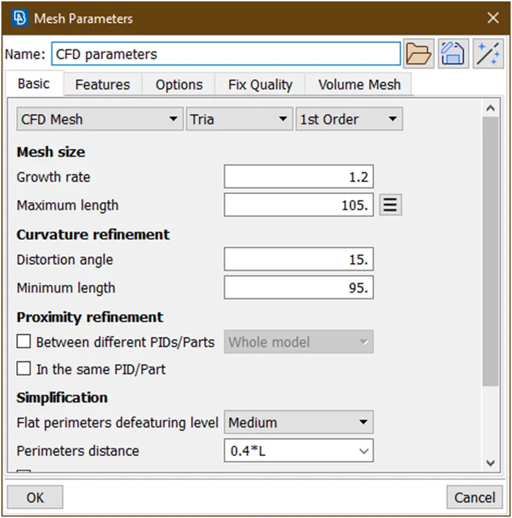
Then goto quality criteria and give max length=500
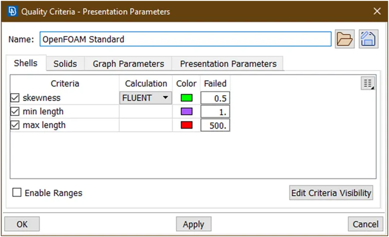
Click on apply and then click ok.
Then goto perimeter-> length and give target value
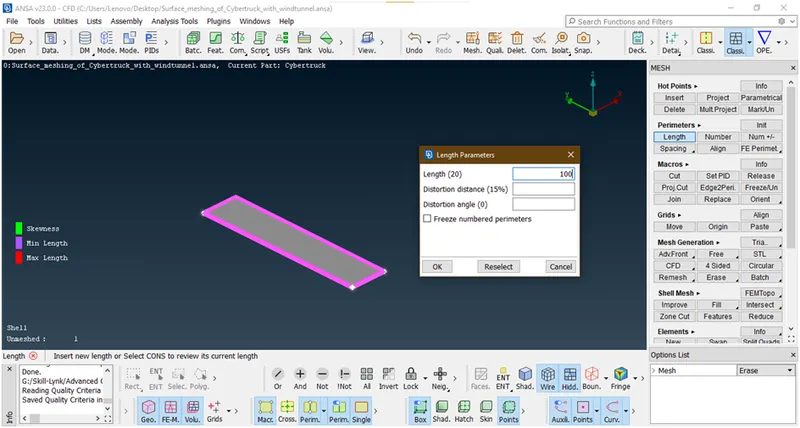
Goto mesh generation-> cfd->visible
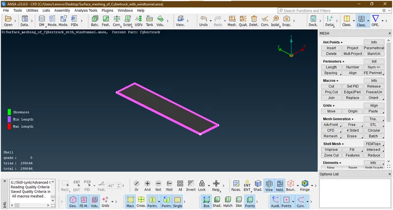
Freeze the mesh
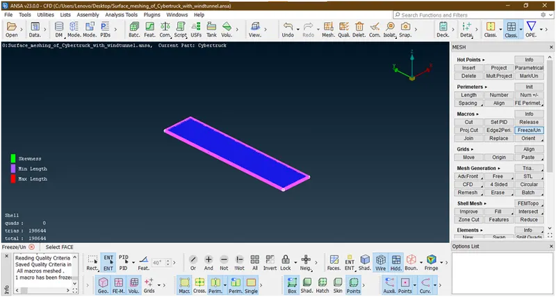
Now its done.
- Lets mesh top face with target length=200.
Goto pid manager and enable top surface
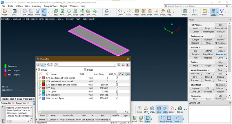
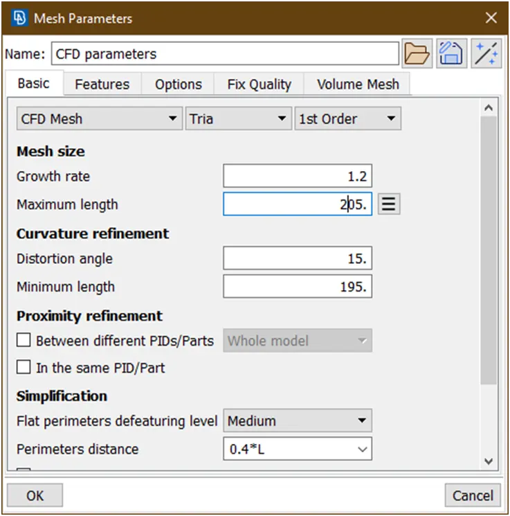
Goto mesh parameter and give min length=195,max length=205
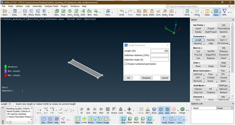
Goto perimeter ->length-> select face-> give target length=200
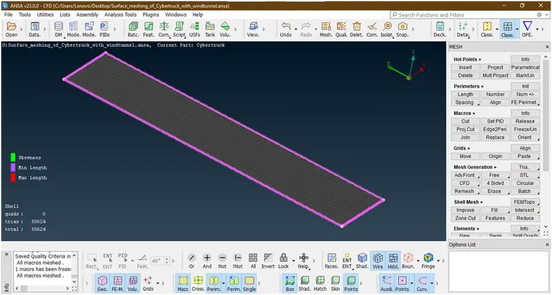
Goto mesh generation->spot mesh->visible
Freeze the mesh
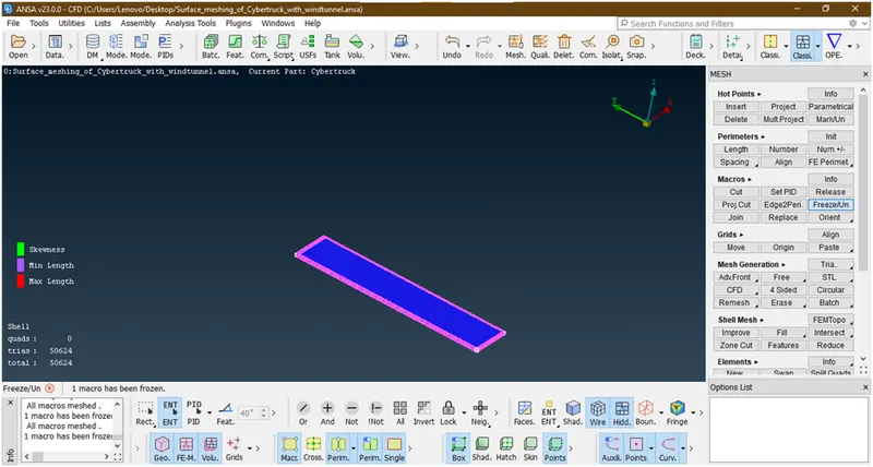
Now its done.
- Lets go for side faces mesh.
Goto pid manager->enable side face.
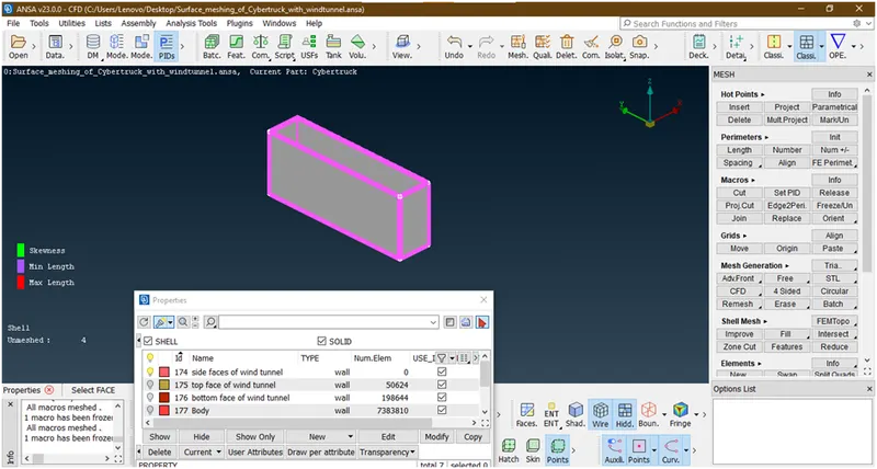
Now here we are giving mesh as grain growth for that Goto perimeter->spacing->manual spacing
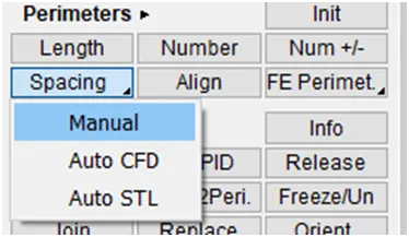
Then select the faces.
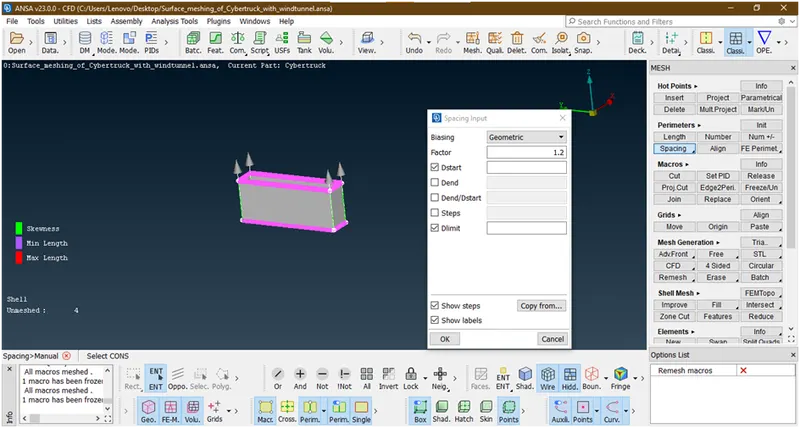
Chose faces in correct direction i.e. arrow start from bottom face and show towards top surface and gives dstart=100,dlimit=200 and click ok.
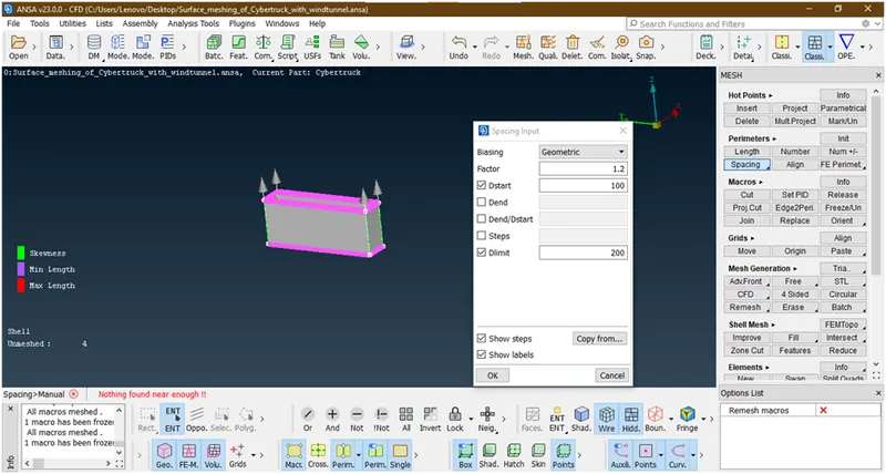
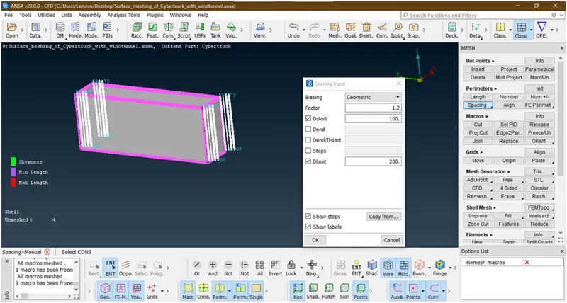
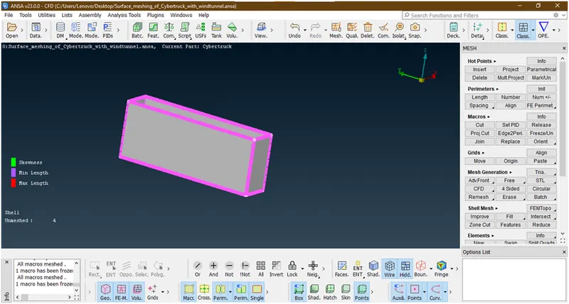
Its applied then press esc.
Then goto mesh generation-> cfd-> visible
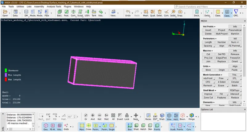
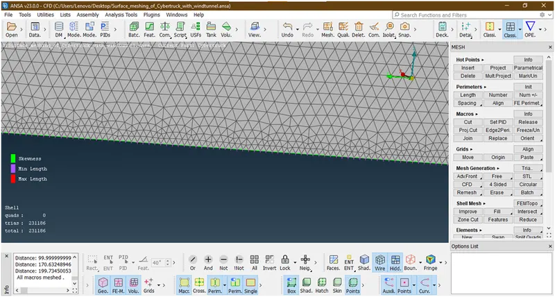
Now its done,
Let freeze it.
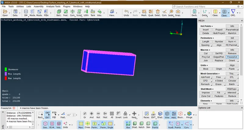
Now its done all meshing.
- Lets enable all part and see any elements are off or not.
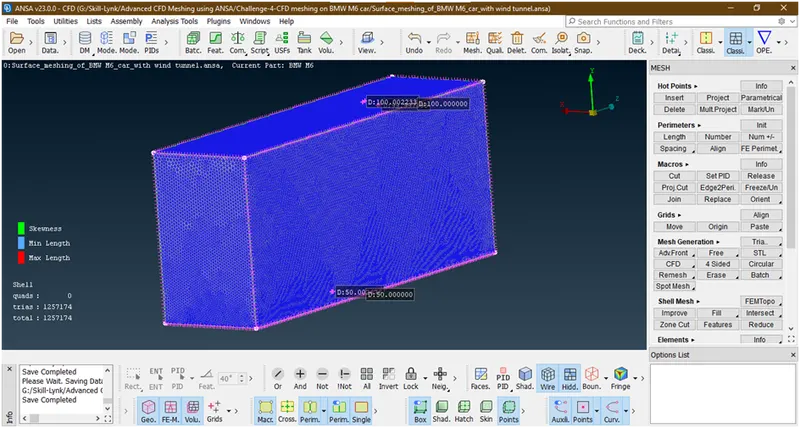
Now we can go for volume mesh.
- Before going forward please unfreeze the macros.goto macros-> freeze/unfreeze -> selcect the total body by right key of mouse only.
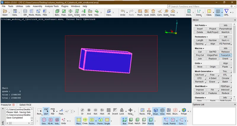
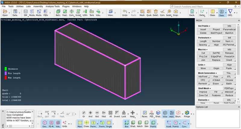
6. Volume meshing of a car with wind tunnel :
- Lets go to volume mesh
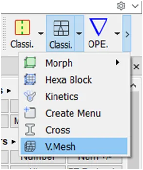
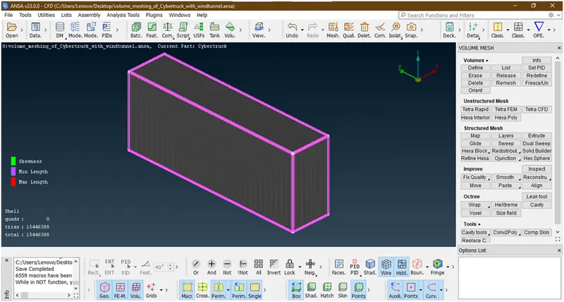
- Goto volumes->defines then a new popup opens
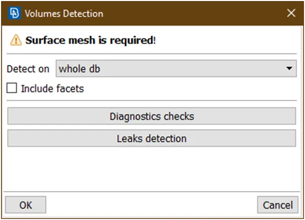
Click on ok then it shows volumes
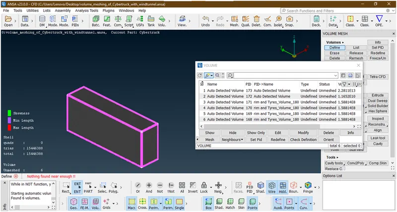
- Let find out which are they and delete those volumes which do not required.
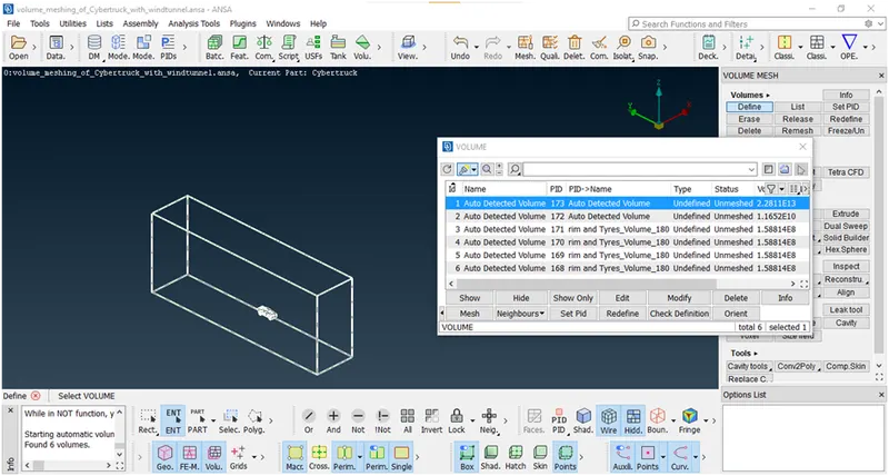
This is the volume considering wind tunnel and truck so we need only this so we are keeping.lets go and check next volume
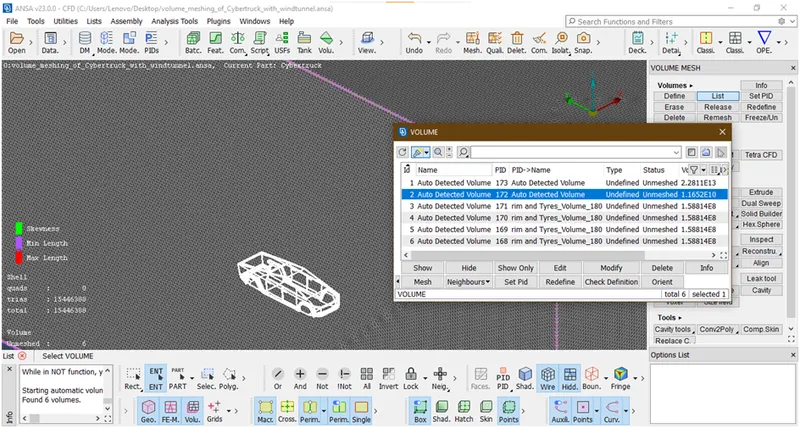
This is the truck volume and don’t need as we have already considered so delete this.for just click on delete
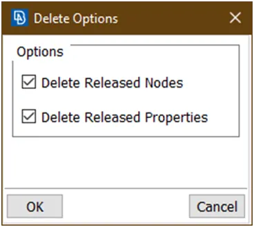
Click ok.then it deleted.Lets check next volume
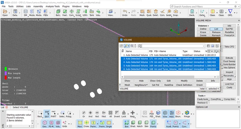
These are all tyres volume so don’t need so we are deleting.
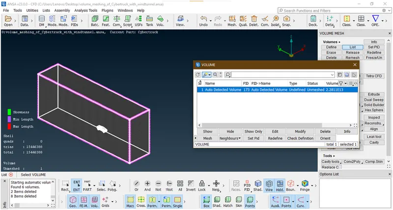
So we have left this only.
- Lets go for meshing
Double click on this undefined,a new popup opens
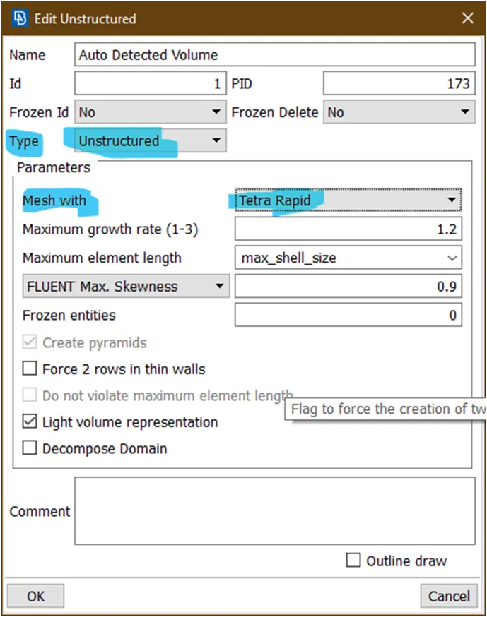
Select above highlited i.e. tetra rapid mesh type and unstructured.Then click on ok.
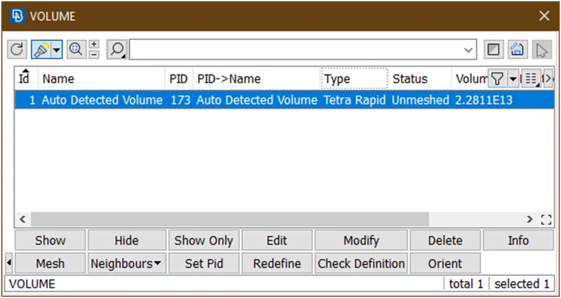
Then click on mesh and wait until mesh to be done.here I have defined the volume but when I am doing volume mesh the application gets stops/crashed. Here I am stopping and concluded.
Results:
- Surface meshing of a car
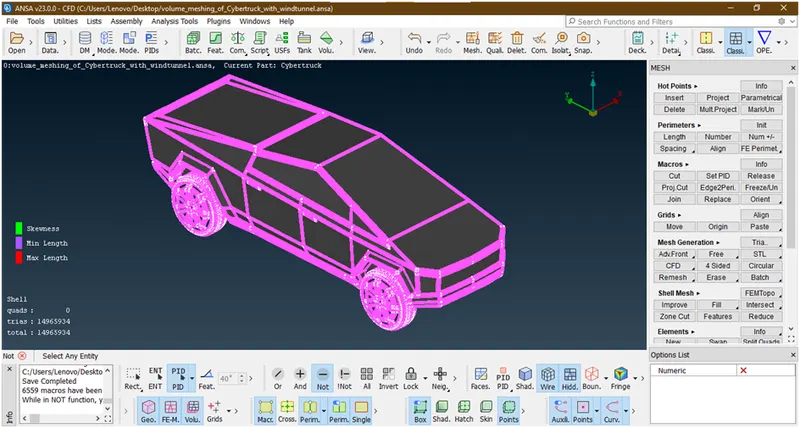
- Surface meshing of a car with wind tunnel
- Volume mesh of car with wind tunnel here I have defined the volume but when I am doing volume mesh the application gets stops/crashed. Here I am stopping and concluded.
Conclusions:
- I have learn how to make wind tunnel.
- I have learn how we can do volume mesh of car for external flow analysis.
Output files:
- Surface meshing of a car with wind tunnel
https://drive.google.com/file/d/1dezQXWkZxyrld0wMnN_vUCYm6rbSPUAr/view?usp=sharing
- Volume mesh of car with wind tunnel
https://drive.google.com/file/d/1JAMFG3UpslVAuJfFscPtqv1YOLBAj-_Q/view?usp=sharing