Week 2- 2R Robotic Arm Challenge
Aim: Write a program in Matlab to simulate the forward kinematics of a 2R Robotic Arm, as shown in the video.
Objective: Create an animation file of the plot.
Theory :
Introduction to forward kinematics:
Kinematics and its types:
- It is a branch of mechanics that deals with the motion of the object without concerned about the forces that causes the motion.
- There are 2-types of kinematics,
- Forward kinematics
- Inverse kinematics
1) Forward kinematics:
- It refers to the kinematic equations which is used to find the position of end effector from the known joint parameters.
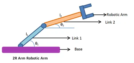
Fig(1): Robotic arm description
2) Inverse kinematics:
- It refers to the kinematic equations which is used to compute the joint parameters from the known positions of end effectors.
2R-Robotic Arm:
- Robotic arm is a machine which helps to move the objects from one place to another and to assemble parts in industries .
- The robotic arm as shown in figure is called 2R-Robotic Arm,where it has ‘Two links and Two rotational joints ’ which allows to freely rotate itself in space.
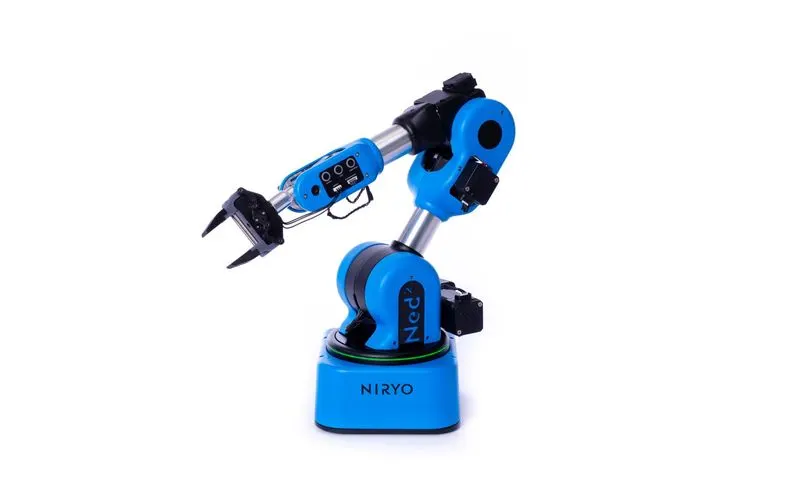
Fig(2): Industrial robot
Program/Code:
% A program in Matlab to simulate the forward kinematics of a 2R Robotic Arm, as shown in the video.

clear all
close all
clc

% Inputs

%Length of link-1(m)
L1=1;

%Range of rotaion for link-1
theta1=linspace(0,90,20);

%length of link-2(m)
L2=0.5;

%Range of rotaion for link-2
theta2=linspace(0,90,20);

%Initializing Counter variable
ct=1;

% We want to crate an animation i.e. location of end effector for different
% different positions of link-1 and link-2  so we are using nested for loop.

for i=1:length(theta1)
    for j=1:length(theta2)

        % Calculating co-ordinates of links
        x0=0;
        y0=0;

        x1=L1*cosd(theta1(i));
        y1=L1*sind(theta1(i));

        x2=x1+L2*cosd(theta2(j));
        y2=y1+L2*sind(theta2(j));

        %Plotting The links
        plot([x0 x1],[y0 y1],[x1 x2],[y1 y2],'LineWidth',3,'marker','.','MarkerSize',30);

        %Defining the axes
        axis([-0.2 2 0 2]);

        %labeling axes
        xlabel('X-axis','FontSize',15,'Color','b');
        ylabel('Y-axis','FontSize',15,'Color','b');

        %Giving title and legend to the plot and curves
        title('Simulation of 2R-Robotic Arm','FontSize',15);
        legend('Link-1','Link-2');
        grid on
        pause(0.01);

        %collecting frames and stored in array 'M'
        M(ct)=getframe(gcf);

        %inrementing counter
        ct=ct+1;
    end
end

figure

%Playing frames in terms of movie/showing animation
movie(M,2);

%crating videowriting file
videofile=VideoWriter('Simulation of Forward kinematics 2R-Robotic arm.avi','Uncompressed AVI');

%writing frames in videofile/importing frames in videofile
open(videofile);
writeVideo(videofile,M);
close(videofile);
Explanation of Code:
- Line-1: Here I am using clear all command to clear the workspace previously stored variables.
- Line-2 : Here I am using close all command to close the previous open figures.
- Line-3 : Here I am use clc command to cleared the command window before starting my new program.
- Line-10 &Line-16: Here I am giving link-1 & link-2 length as 1m & 0.5m.
- Line-13 & Line-19: Here I am giving rotational angle of links w.r.t.base/x-axis as theta1 & theta2 in terms of array by using linspace command.
- Line-22: Here we are initializing counter variable ‘ct’ to stored each frame at new position of array
- Line-27 & Line-62: Here we want to create an animation of robotic arm i.e. we want to capture the position of arm at different locations and find out the co-ordinates of links at each angle of link-1 and link-2 so that’s why we are using nested for loop.
From line 31 to line38 we are finding out the starting and final co-ordinates of links 1&2 at each angle by using simple trigonometry and maths calculation and creating line between two co-ordinates and plotting a graph at each angle of link-1 and link-2 as shown in ‘Line-41’ and we are stored this every figure in array ‘M’ i.e. stucting the figure by using command ’getframe(gcf)’ as shown in ’Line-57’.here gcf stands for ‘get the current figure’. ‘Line-47 & 48’ explains the we are labelling the axes.’Line-51’ explaining, we are giving title to the figure.
Line-52 ,explaining that we are giving names to the lines that we are plot by using command ‘legend’ .
This all process want to repeat for each and every angular position of links that’s why we are using nested for loop.
- Line-67: We are showing the animation 2-times by using command ‘movie’.
- Line-70: We are creating a videowriter file by using command ‘VideoWriter’ and in this file we are creating video of name ’Simulation of forward kinematic 2R-robotic arm’ of .avi formate and stored as uncompressed avi file to visualise the video clearly.
- Line 73- Line-75: now we are opening the vieowriter file save as ‘videofile’ name by using command ‘open(videofile)’ as given in Line-73.
Line-74 explain as we are copying the data from M-array to the videofile.
Line-75 explain we are giving the command close(vidiofile) to crate video and save it to location where program is save.
Errors:
Here I am not get any error while running the program/code.
Output:
Simulation of Forward kinematics 2R-robotic arm :
https://drive.google.com/file/d/1VxVRkswTD0J3dwOo-87ibvC9ciuW336s/view?usp=sharing
Explanation of output:
We are creating and showing the animation/simulation of robotic arm at different different locations of links how it looks by changing the angles of link w.r.t. base/x-axis.