Week 4 Challenge : CFD Meshing for BMW car
https://drive.google.com/file/d/1NuW8xf82t-9-k3xdLvlSosj3F2pI6-z2/view?usp=sharing
AIM:
- The main aim of this challenge for the given model is,
(1) To solve all the geometrical errors and assign appropriate PIDs.
(2) To perform meshing with the given target length and element quality criteria as given in the challenge.
(3) And finally, create the meshing wind tunnel volume with tetra elements for the model.
PROCEDURE:
GEOMETRICAL CLEANUP:
- Import geometry from file->open->file location->challenge4.ansa
- Like always we do in other challenges enable labels to show the names of the tools.
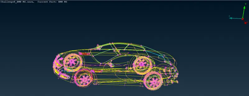
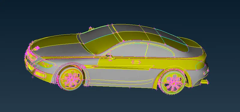
- Click on the shadow tool to enable surfaces on the model.
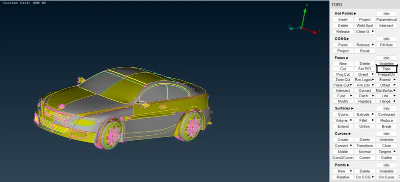
- Always in the beginning go for the topo option for automatic corrections.
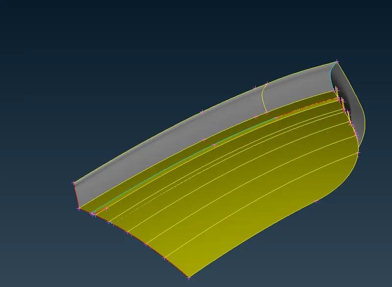
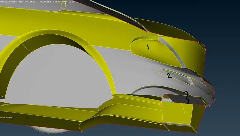
- If closely observing the model, The shapes of the edges are not fine and curved.
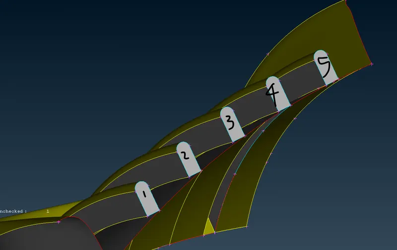
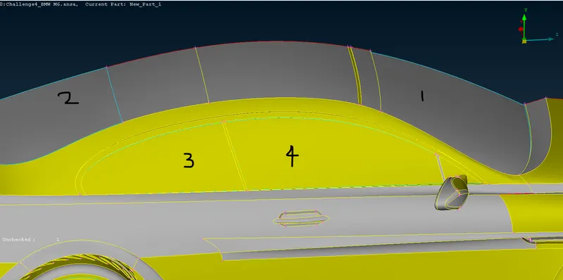
- For example, Before 1,2,3
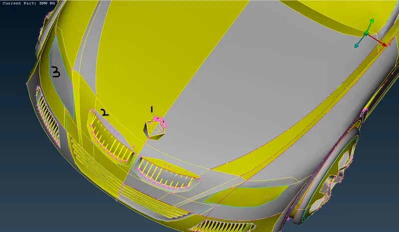
- So, we can go for the resolution change option to make it the correct shape.
- Go to classic->mesh->perimeters->length->select the model->give 1mm in perimeter.
- The shapes are perfect after the resolution.
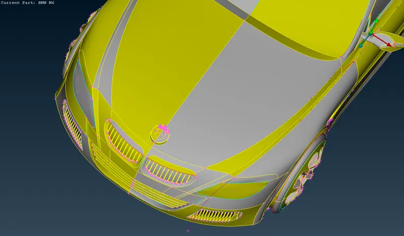
- If we closely observe half of the part, Its symmetry to the other half.
- So, what we can do is, we can universal delete half of the parts except the BMW logo. Because it's not symmetry to the other half.
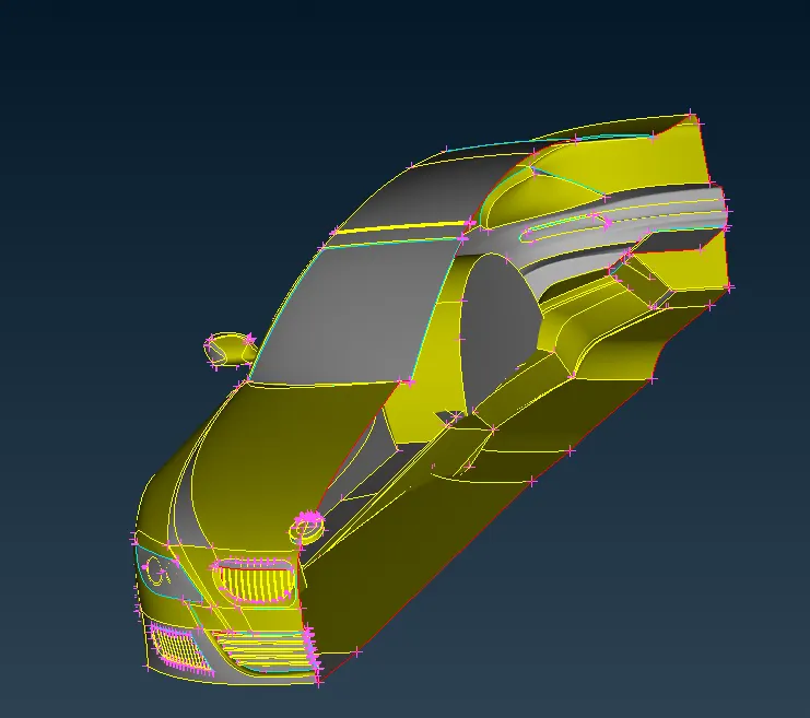
- Make sure The logo should not deleted completely.
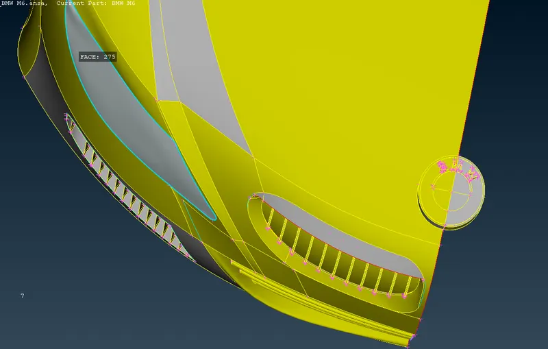
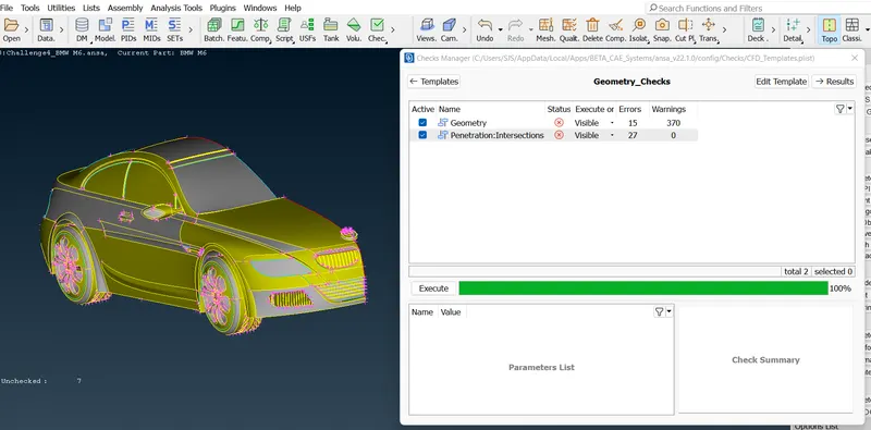
- Go for a geometry check and see the errors present in the model.
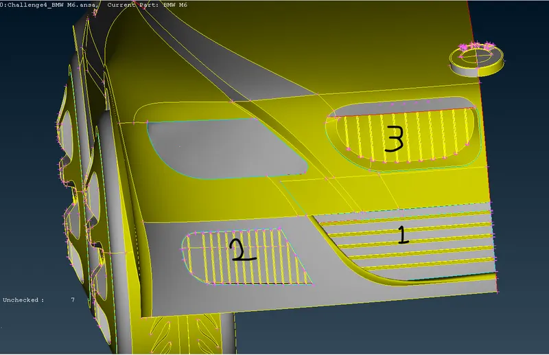
- Initially we start with these 3 grills. It has more unwanted internal volumes that we don't need.
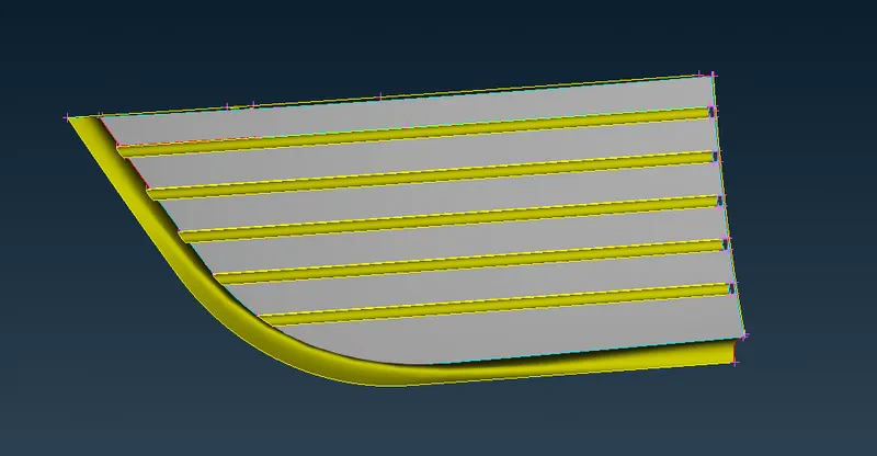
- Isolate grill 1 using the NOT option and start working on that.
- Before do the changes on the grill, Click the lock option
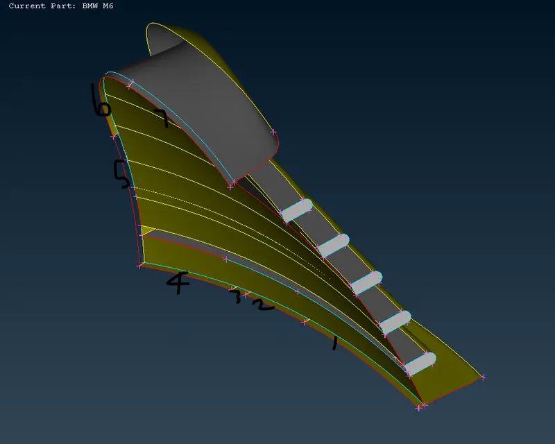
- Delete extra surfaces that are not needed.
- Deleted extra surfaces.
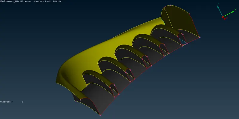
- Delete these surfaces.
- Deleted view.
- Project the side cons and make a new surface over there to connect the edges.
- TOPO->CONS->PROJECT->SELECT THE SURFACES->MIDDLE CLICK.
- Projected view.
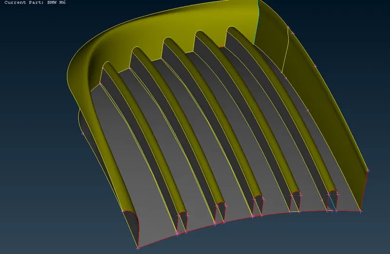
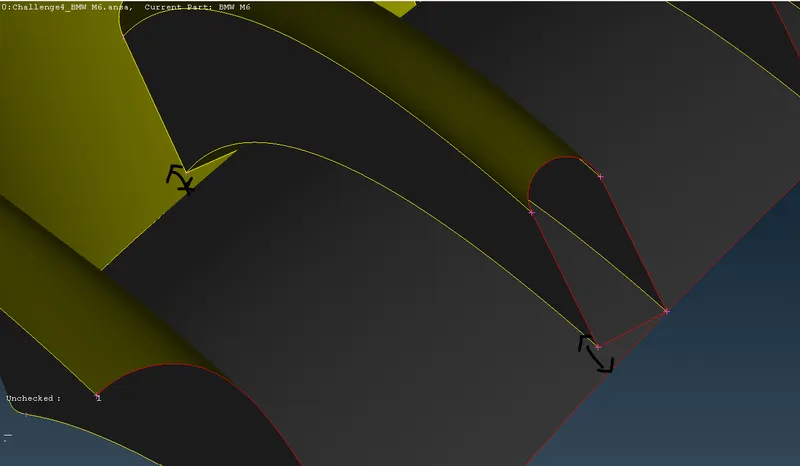
- If we see the projected line, it is not perfectly curved so give resolution as 1.
- And in the end, the edges are not connected. So, use the cut option to connect the edges.
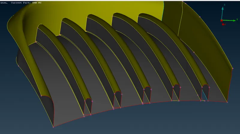
- Now, delete the surface and create it perfectly.
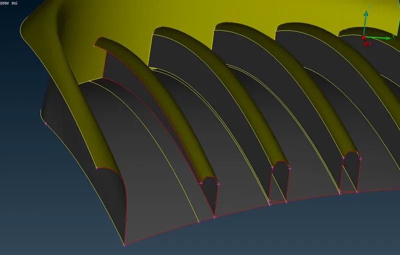
- Check before creating it.
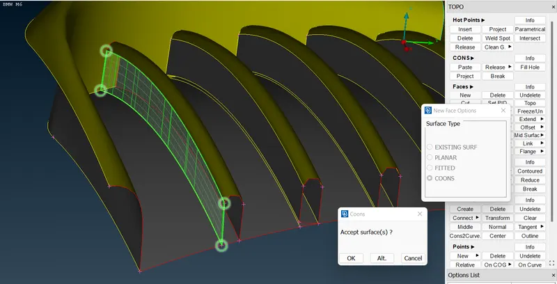
- We have to delete the under surface but it is not selecting only that surface, so project another side and delete it.
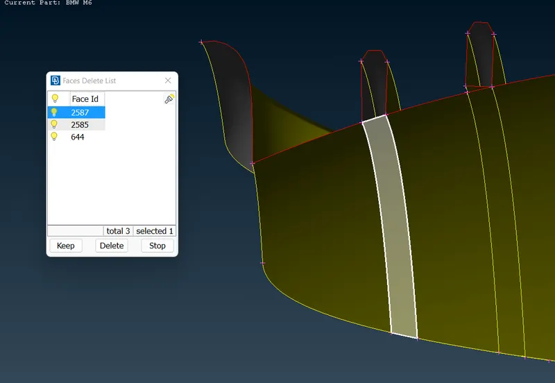
- Now, we have to delete this surface.
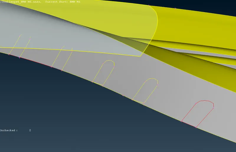
- Before deleting the surface project it.
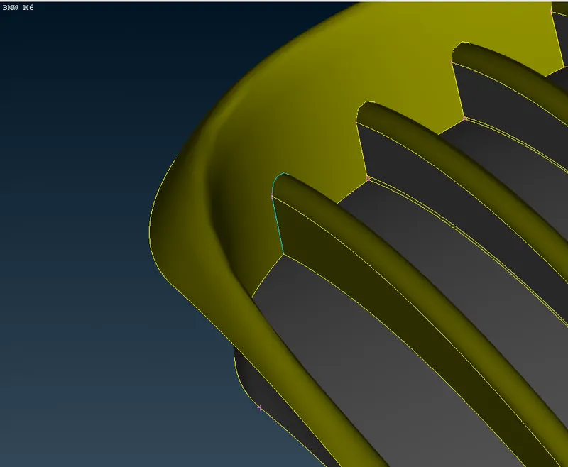
- Now it's perfect and does like this for others also.
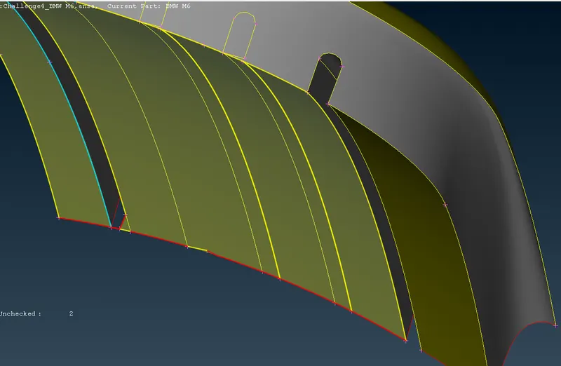
- Now it's perfectly done.
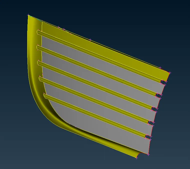
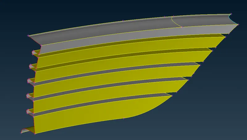
- Start with the second grill as mentioned above.
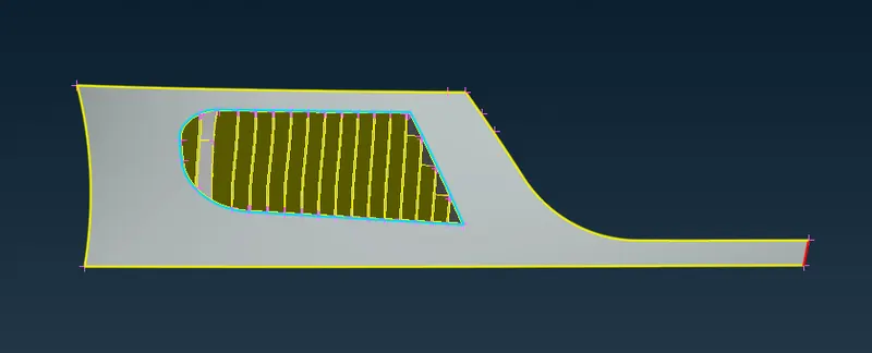
- Change ENT mode to PID MODE.
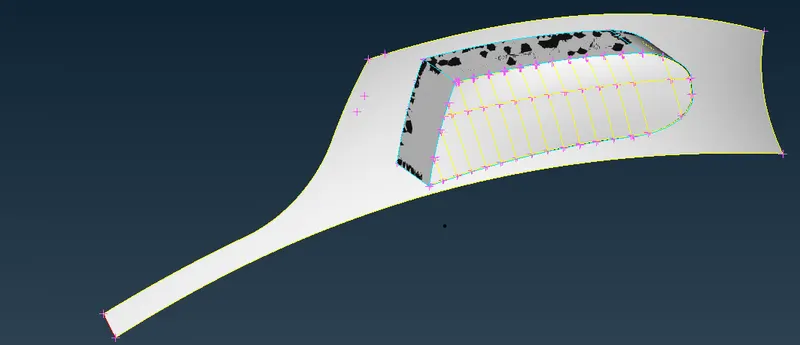
- From this we can observe that the surface is overlapping. So try to resolve it by deleting it.
- Check using the NOT option to what is happening inside.
- If we observe the edges it's not properly connected and some distortions are there.
- So, let's try to resolve it.
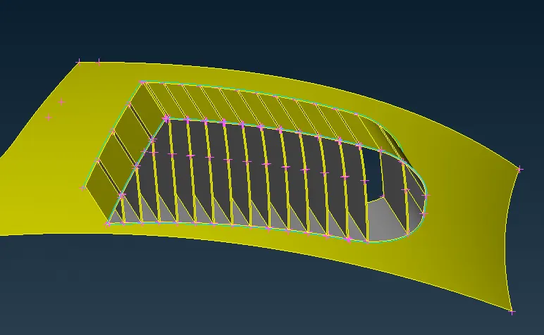
- Create a surface from the edge to 0.2mm distance using a parametric hot point and faces->new surface creation option.
- Create PID name to separate the surfaces and do intersection.
- Make sure the arrow direction is correct.
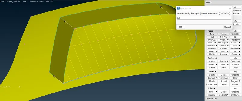
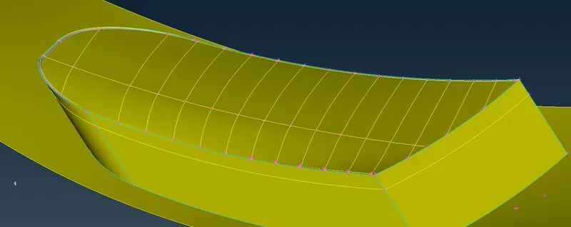
- After creating the hot points connect the hot points using the CUT option.
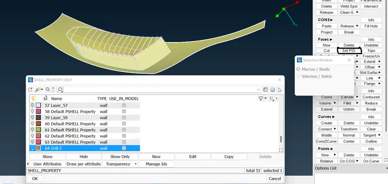
- Give the name for this grill using faces->set PID option.
- Now create the new surfaces in the connected 0.2mm distance.
- Topo->Faces->New->Fitted->select the points using Loop option->Middle click.
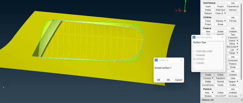
- It's created perfectly.
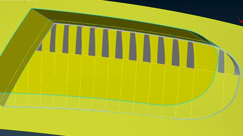
- Name the new surface and separate it.
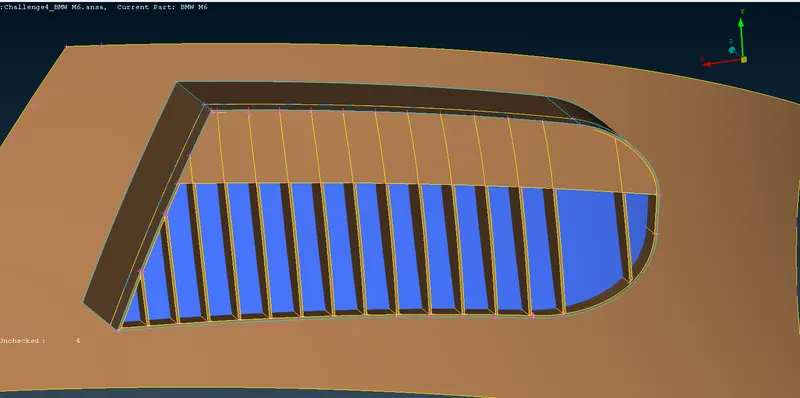
- Now do intersection and show the final view of the grill 2.
- It's perfectly done.
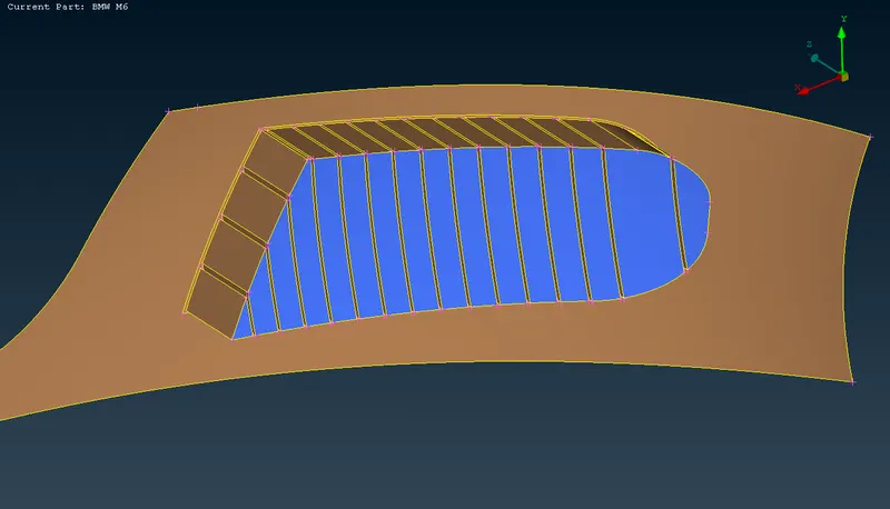
- Start with the 3rd grill as mentioned above.
- Clear unwanted surfaces and single, triple cons in the grill.
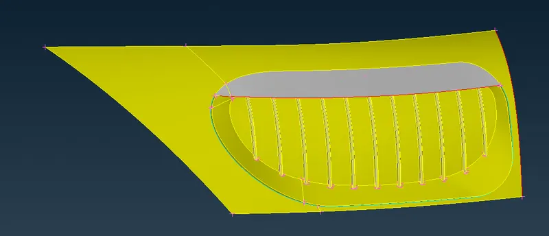
- Delete the extra triple con surfaces.
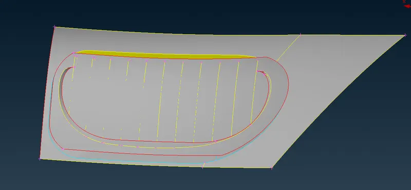
- Triple cons are gone in the back and front view after deleting extra surfaces.
- Back side view:
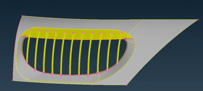
- Front side view:
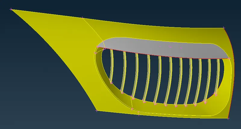
- we can delete the back side closed surface to connect all the grills in a single volume surface.
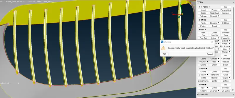
- Deleted view:
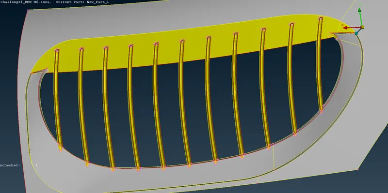
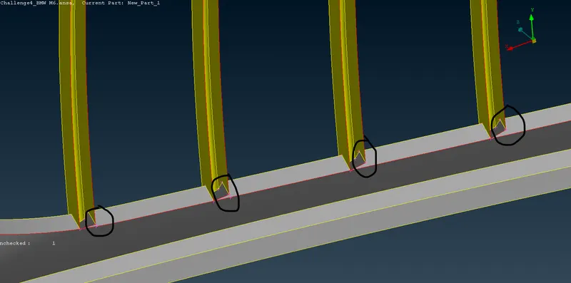
- If we clearly observe the bottom, there is no proper joint.
- So, we can use cut option to connect the grill joints.
- Created cut between grill joints.
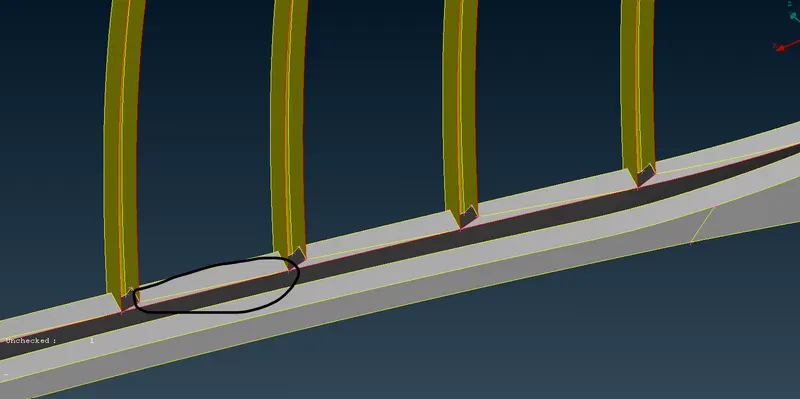
- Now we can directly use the universal delete option to delete the extra surfaces after joining the grills.
- Select the surfaces->middle click->ok.
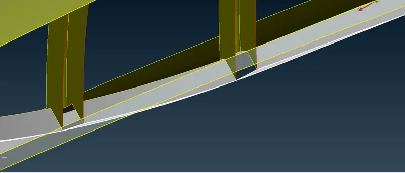
- Deleted view.
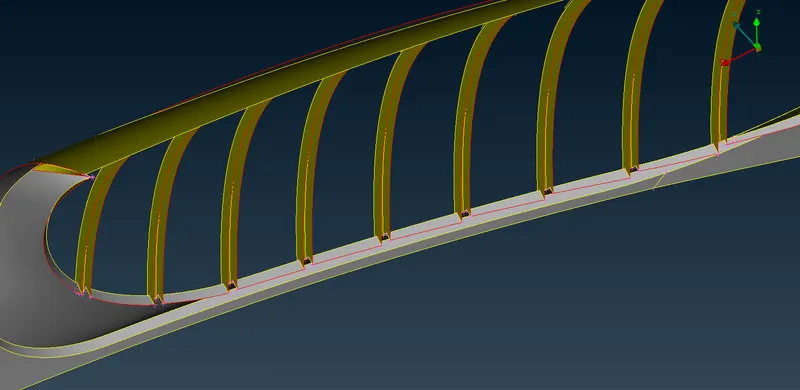
- Create a surface between the grills as shown in the picture.
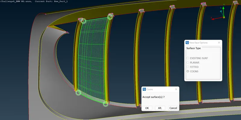
- Surfaces has been created except for the corner.
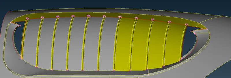
- In the right cornor what we can do is, we can cut some surfaces to make it correct.
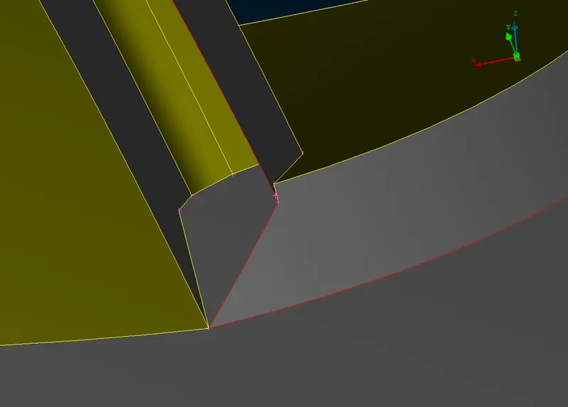
- Correct view.
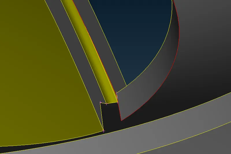
- Now hide the other surfaces to make a plane cut.
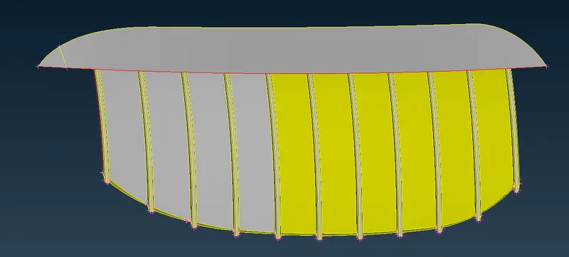
- Create a hot point in the middle to use the plane cut.
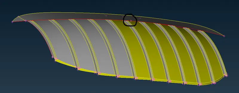
- Select plane cut->single->3 hot points->middle click->ok.
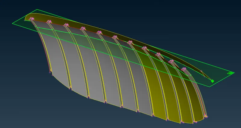
- Now it is perfectly cut.
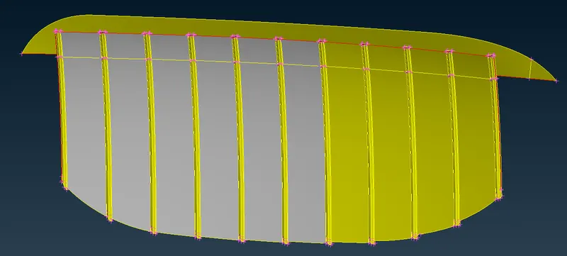
- We can delete the upper surface.
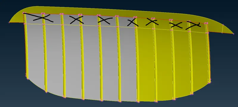
- Delete this surface by using the universal delete tool.
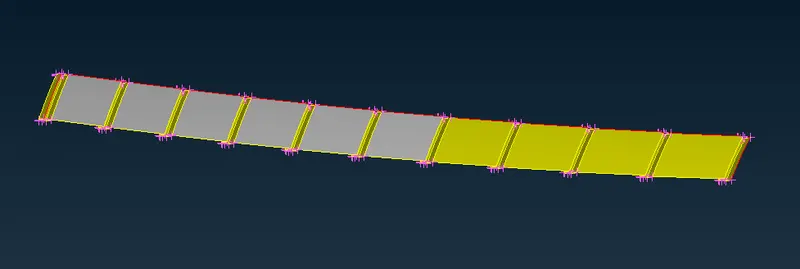
- Deleted view.
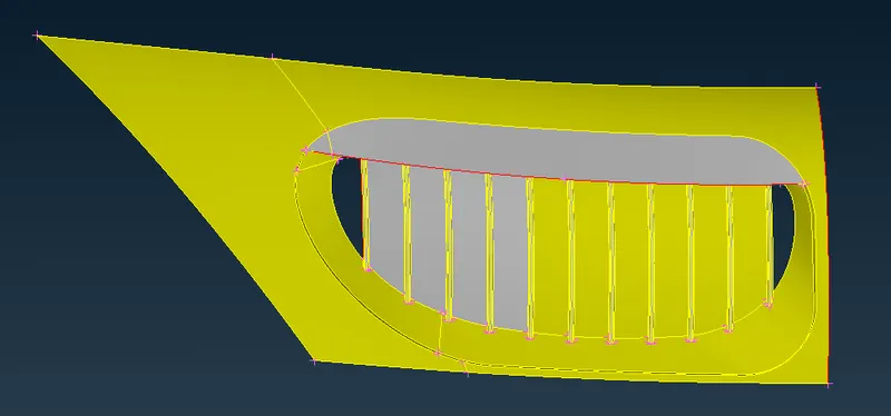
- Next go for geometry check.
- It is showing 1 intersection error. Resolve the error and create a proper closed surface.
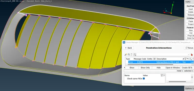
- If we clearly observe the intersection, some surfaces are going inside. So delete that and create the correct one.
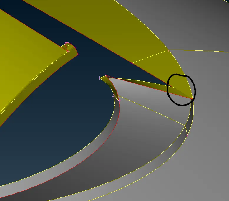
- In the back side I have deleted some surfaces.
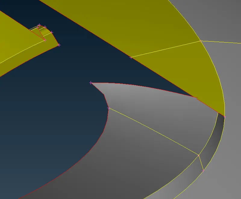
- Check the front portion. The lower surface is intersecting the upper one.
- So cut the surface and delete it. Then create a new perfect surface.
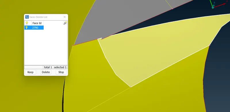
- Here create a hot point.
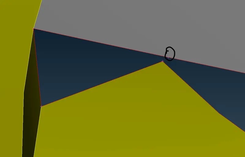
- Create the surface.
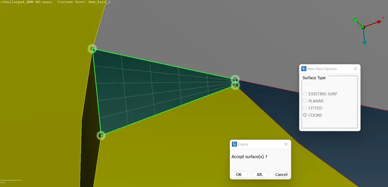
- Now try to close the open surface here.
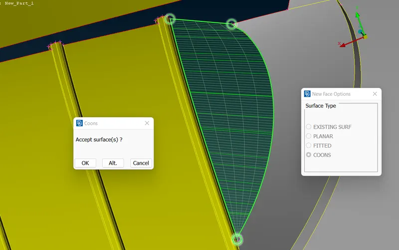
- Create hot point in the upper surface and close the surface.
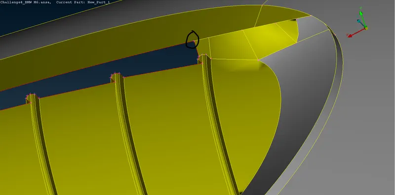
- It's done over here. Go for the other side.
- The same thing we have to do it here also.
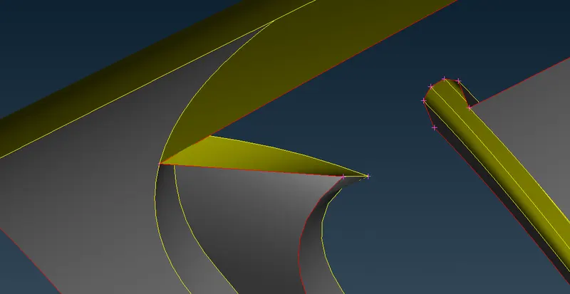
- Surface has been created.
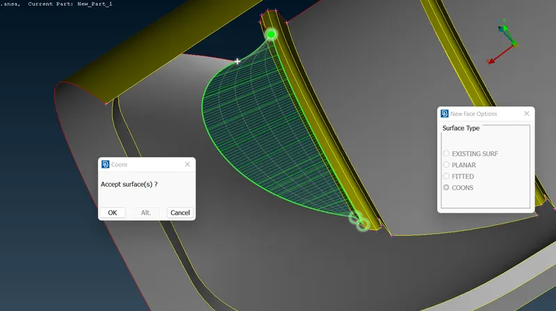
- Put hot points in the upper and lower surface then close it.
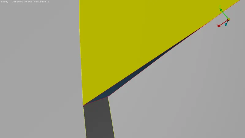
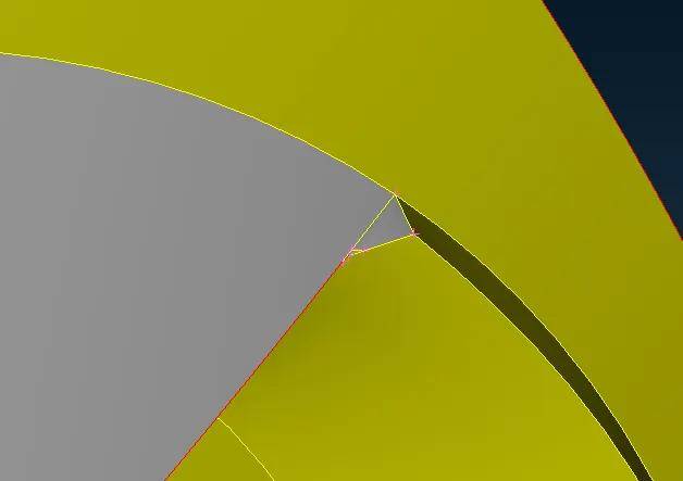
- In the other side also we have closed the surface.
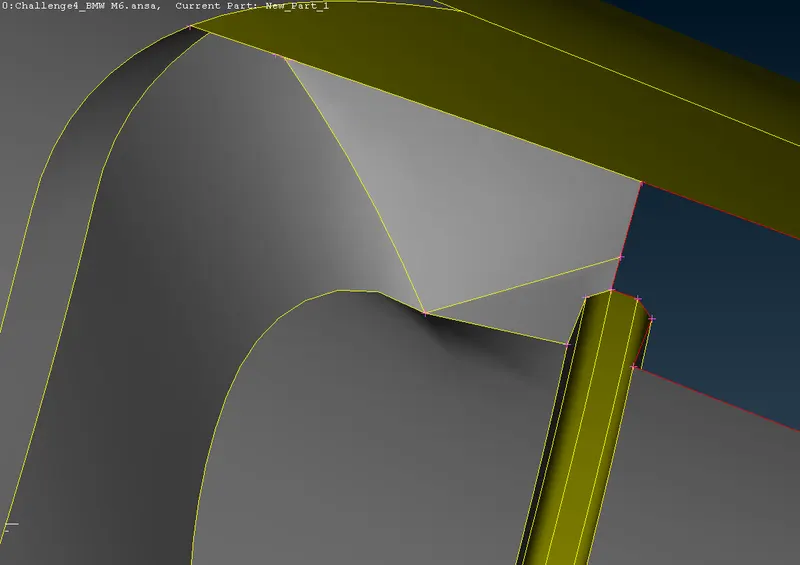
- Now we are going to close the surface by creating hot points and a new option.
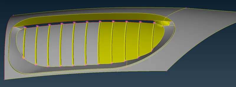
- Grill 3 geometrical errors has been completed.
- Final view:
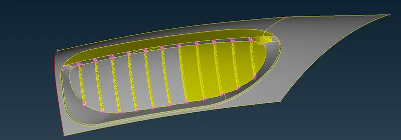
- Start with this light and do the changes.
- Outside view:
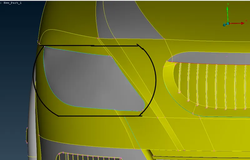
- Inside view:
- We don't need the inside parts if outside surfaces are present. So we can delete all the inside parts.
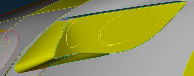
- After deleting parts also it's showing one red con.
- Try to observe what is happening there.
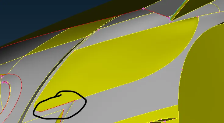
- On the same surface 2 cons are there, Instead we can connect both cons using CONS->PASTE option.
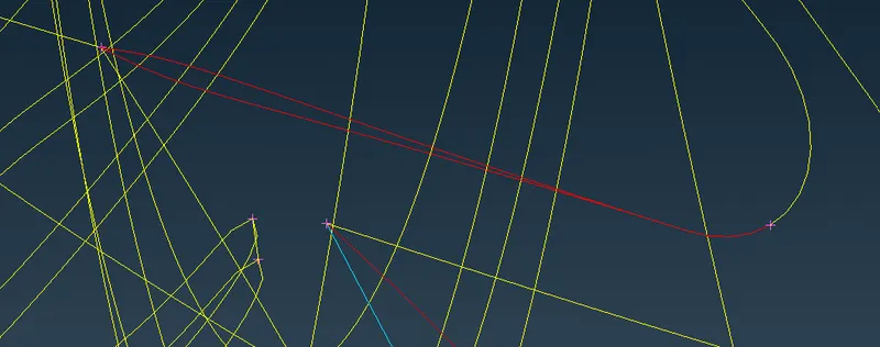
- Select the cons->middle click->ok.
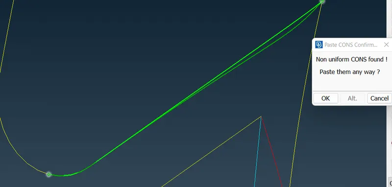
- Now it's connected and proper.
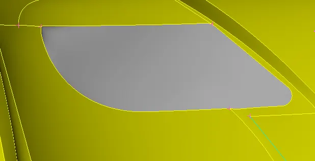
- Now do geometrical check, If we see there is no intersection error in 3 grills and in the front light.
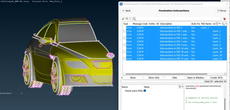
- Isolate the BMW logo and clear the errors.
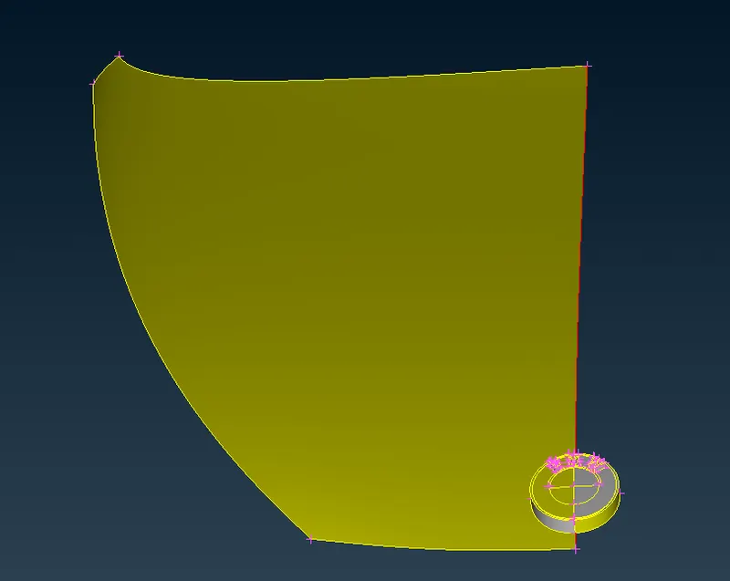
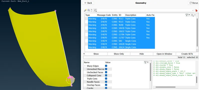
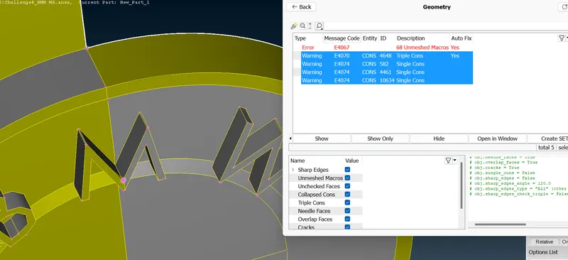
- Go for geometry check, Here the triple cons and single cons are showing as an error.
- So always check the warnings and if we can clear the warning also, try to clear it.
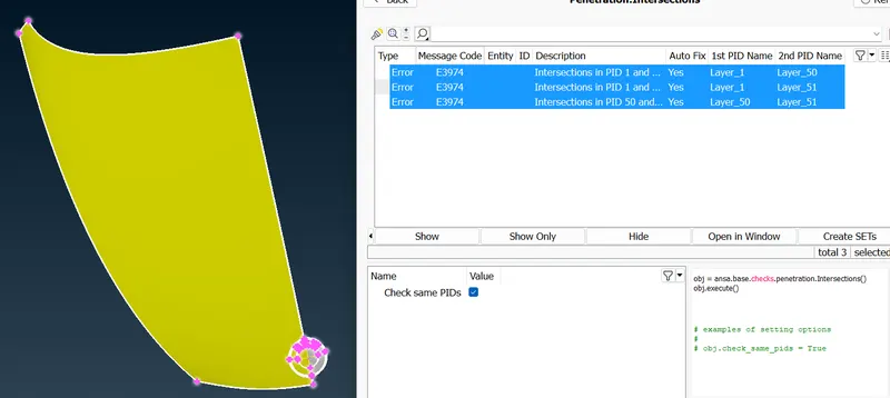
- All the surface itself showing as an intersection error. Because the logo is connected on the surface.
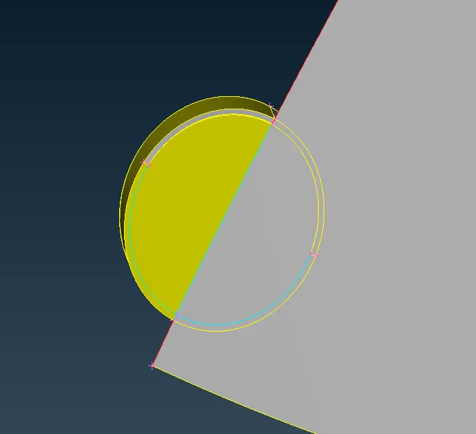
- Now delete the unwated extra surfaces which are present inside the logo.
- Because here we need only the outer surface.
- Inside view, After deleting the inside surface it is showing red con.
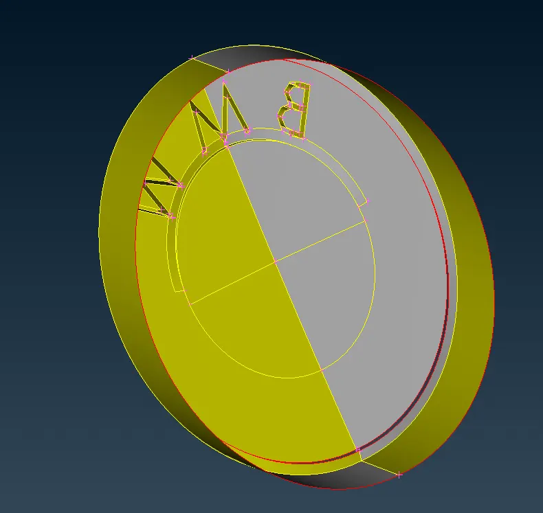
- Delete the X mark and create a new surface.
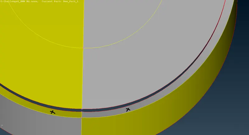
- Surface created view.
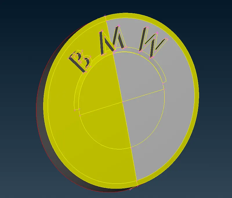
- The has been projected by cons->project.
- And delete the surface.
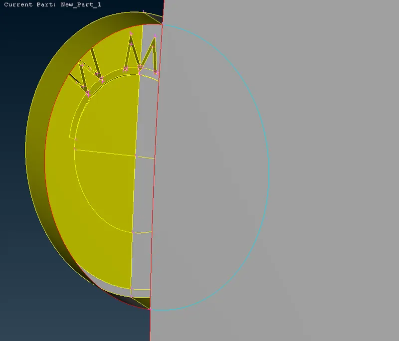
- It's done in the back side.
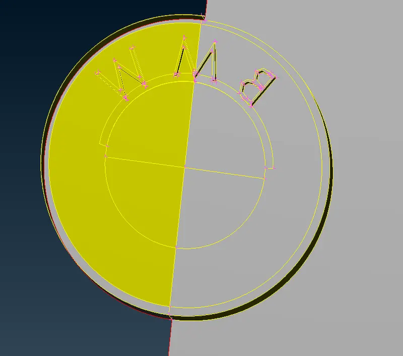
- Do geometry check again and do the changes.
- There is a triple con present on the logo name "M". Clear that triple con.
- The single cons are coming in the half part boundry. So we can neglect that cons.
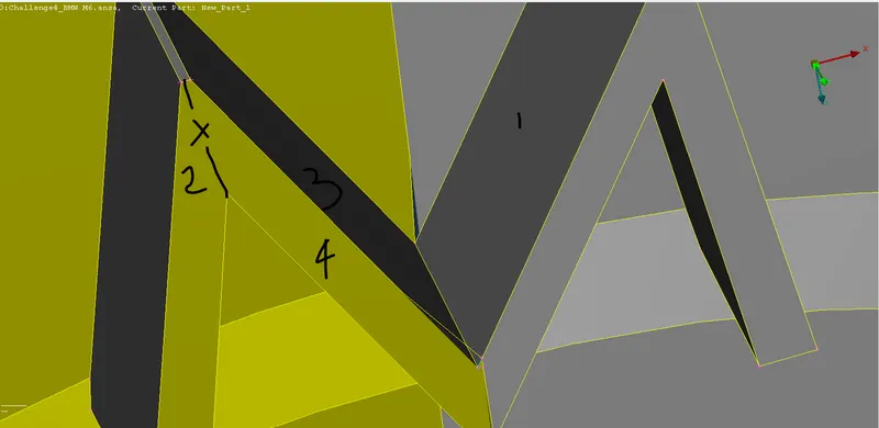
- Delete surface 1, make a cut as shown in the X and delete surface 3.
- Create surface 3 newly and delete surface 4 and create it.
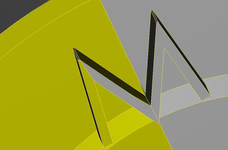
- Now logo "M" is perfect.
- Do geometry check again. It's is showing only half part of the boundary.
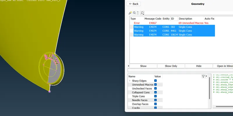
- Now isolate this part and start work on it.
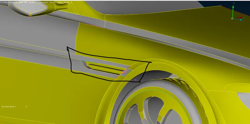
- In this part there are many single cons are present.
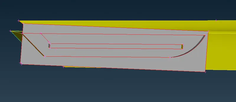
- If we observe the grey surface which is intersecting the other surface.
- So delete the grey surface.
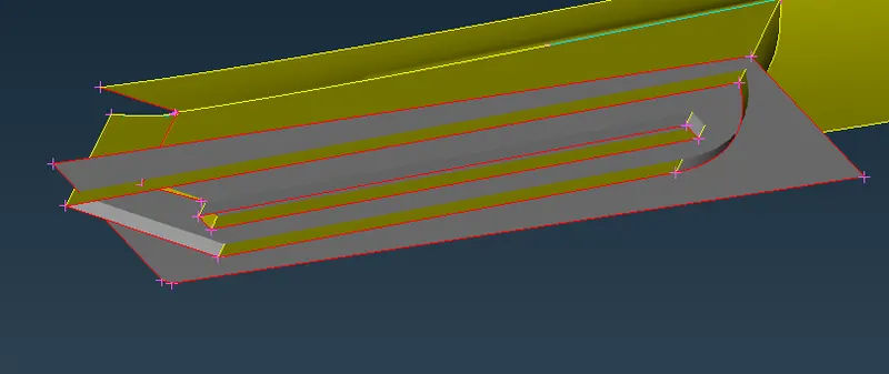
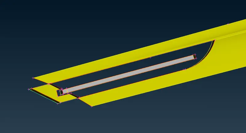
- Here we are going to extend the the part to make it as a single box surface.
- But to use this option, there should be a single coon to extend.
- TOPO->FACES->EXTEND->TARGET->SELECT THE SINGLE COON->SELECT THE SURFACE which needs to be extend->MIDDLE CLICK.
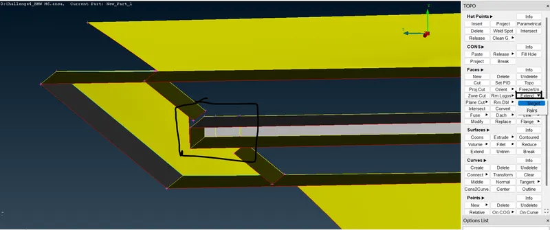
- Surface has been extended and back side surface has been deleted.
- Now release the con to extend again.
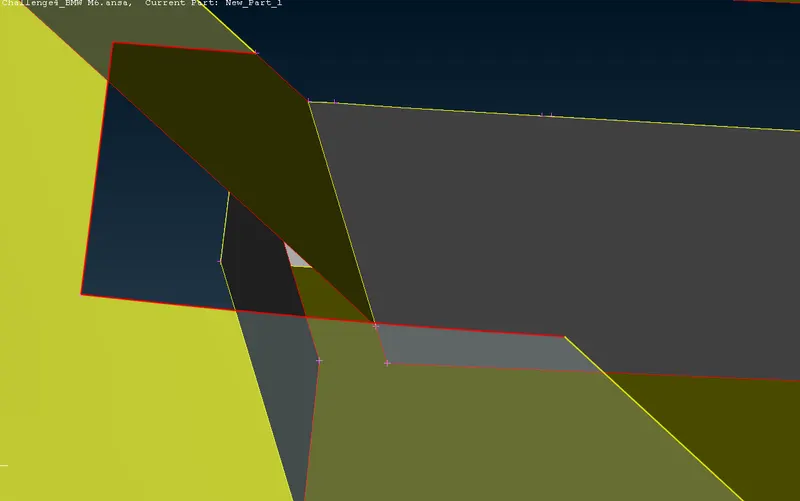
- Surface has been extended.
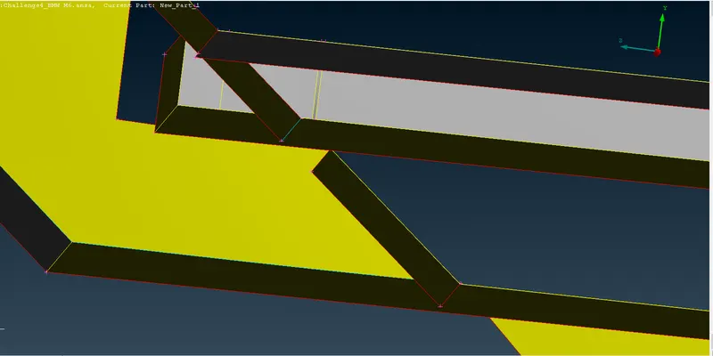
- Other unwanted surfaces are deleted.
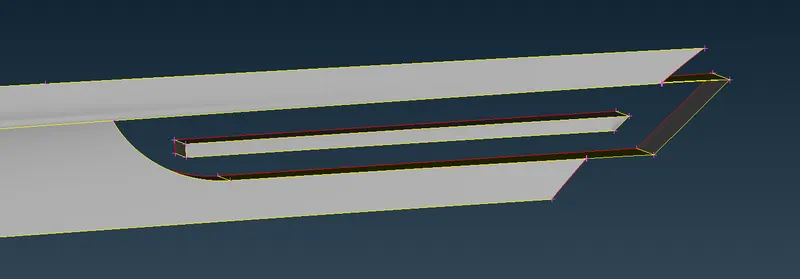
- Inner surface view.
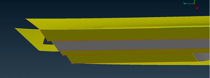
- Now delete the extra extended surface using project cut.
- Project cut will cut the surface perpendicular.
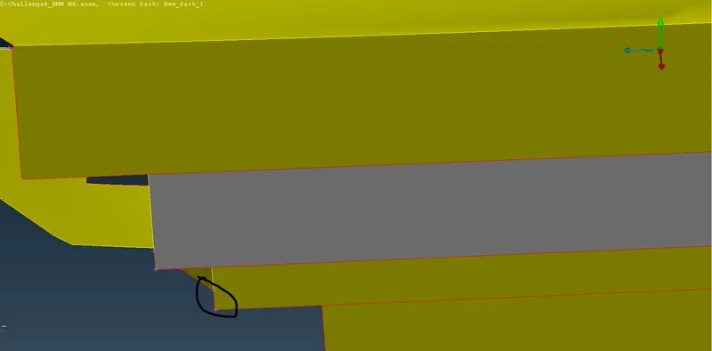
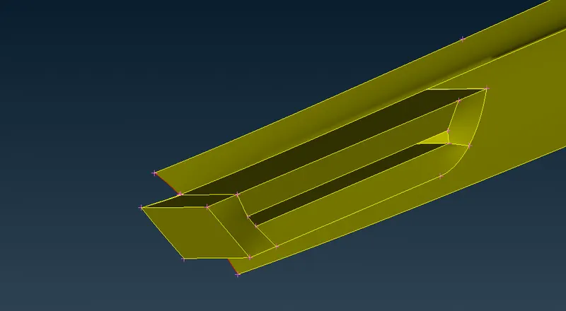
- Finally close the surfaces.
- Back side view:
- Front side view:
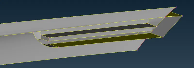
- Here it is completly done.
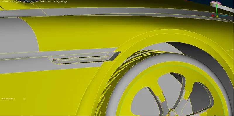
- Now do geometry check, whether any errors are coming here.
- There is no intersection and surface errors showing here.
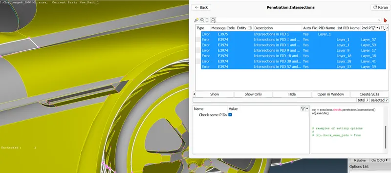
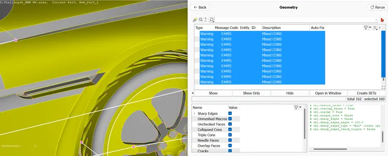
- In these surfaces there are one more surface that is present.
- So delete it.
- After single deletion it came to yellow coon.
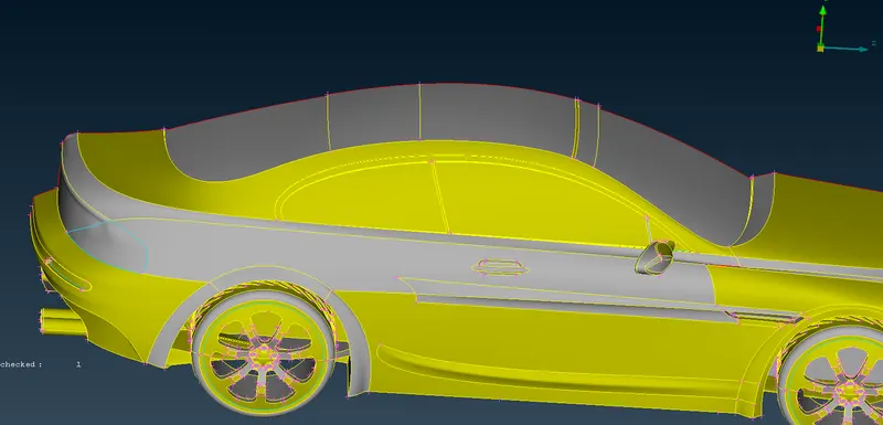
- Start with the side mirror.Delete the extra surfaces.
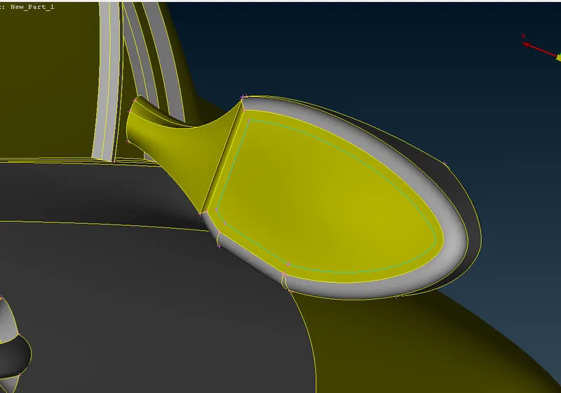
- After deleting 3 times only inside surfaces and glitches are discovered.
- Delete the surfaces and create new one.
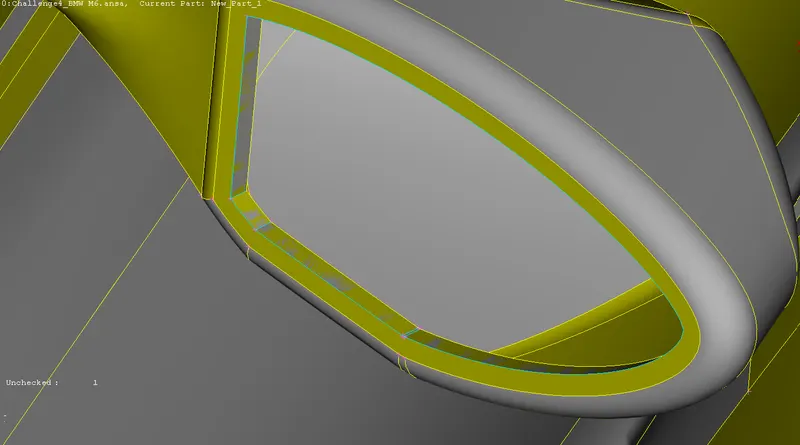
- New surface has been created.
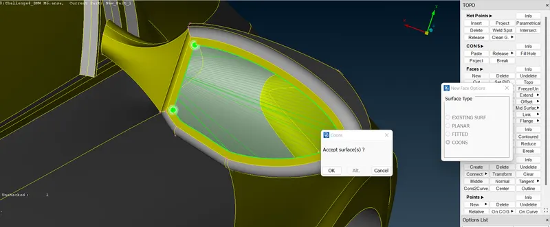
- If we hide the merged surface of the mirror, there is one intersection surface present.
- Delete that surface.
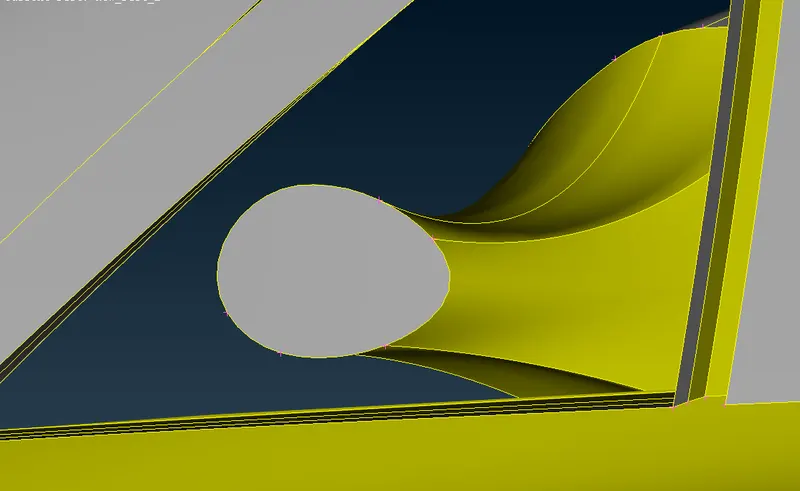
- Now do project and topo.
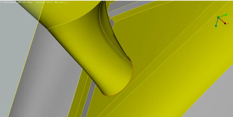
- View from inside:
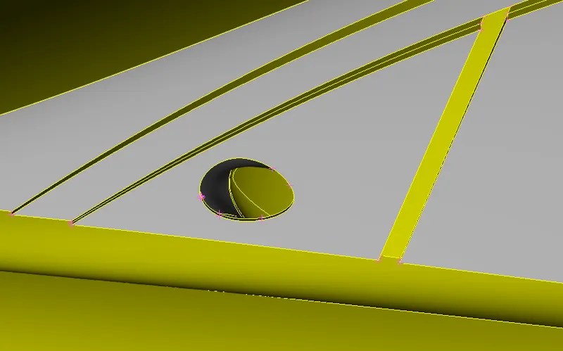
- Clear the triple cons.
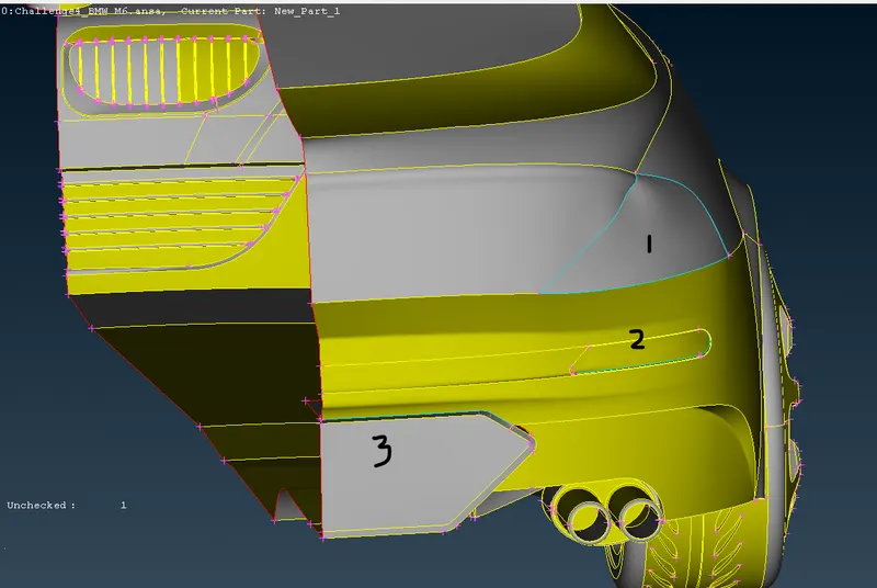
- Inside view:
- Delete all the inside surfaces.
- There is no triple cons after deleting inside unwanted surfaces.
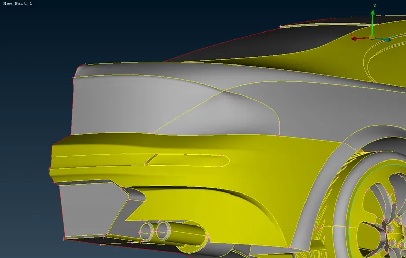
- If we clearly observe, one yellow coon which is coming on the surface alone.
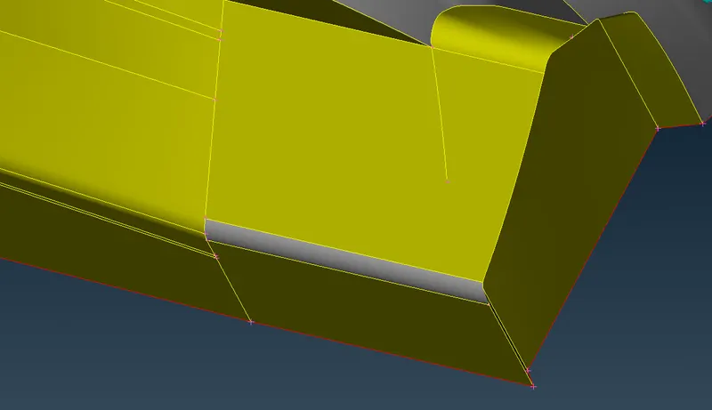
- See the surface on the front side.
- Which is intersecting on the other one, so make a cut and delete that.
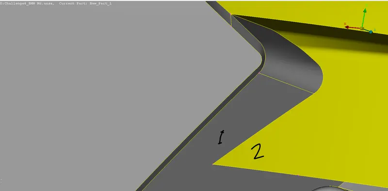
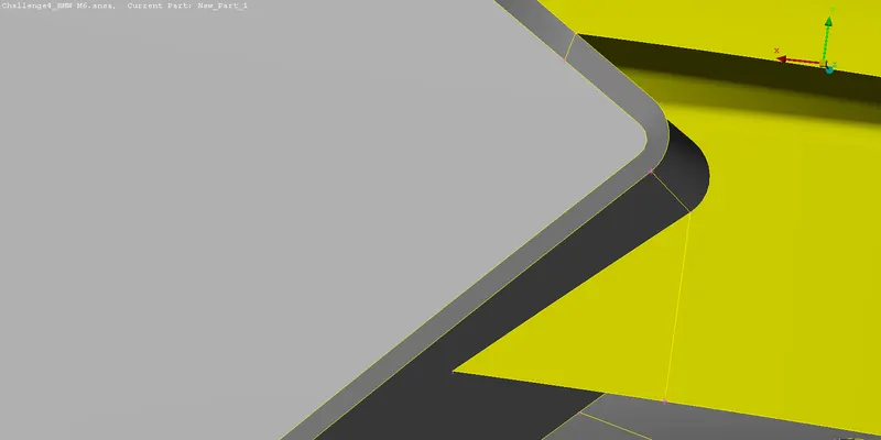
- Crete a surface over there.
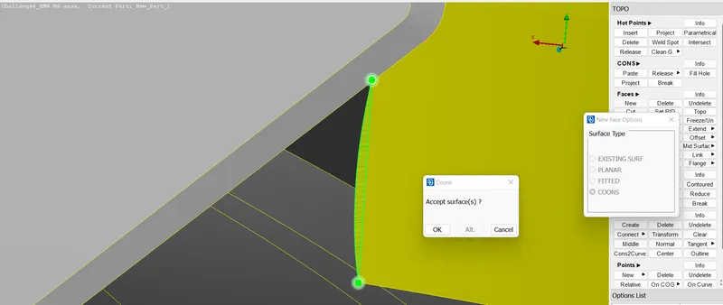
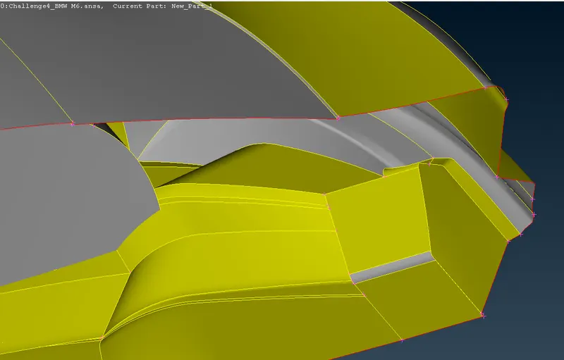
- Now there is no extra con on the surface.
- Do a geometry check and see the remaining intersection errors.
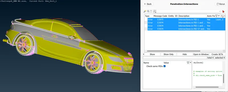
- If we see the tyres, so many surfaces are intersecting the tyres.
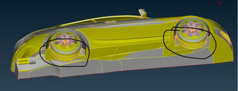
- Click PID REGION -> hide the tyres and lock it.
- Delete the surfaces which is unnecessary.
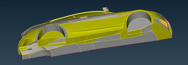
- Before doing floor surface cleanup, we have to use the CONS2CURVES option under the curves to create the con curves.
- Like this create for others too.
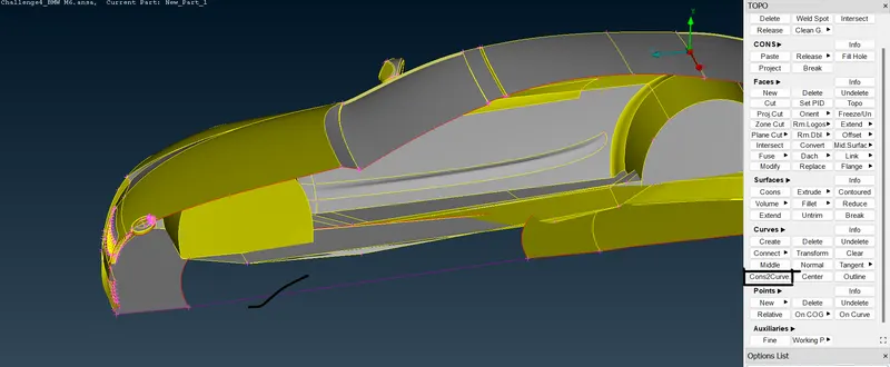
- Delete the unnecessary surfaces which are intersecting the tyre.
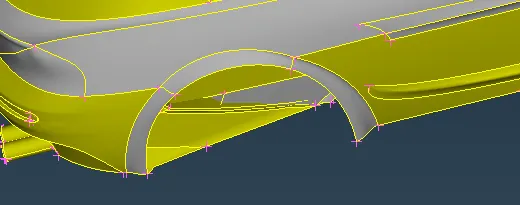
- We can delte all the unnecessary surfaces which are present inside the car.
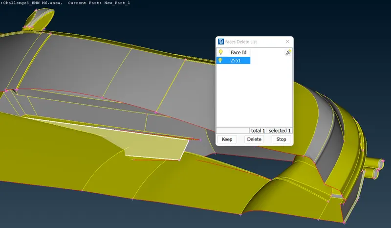
- These are the remaining parts exixting in the tyre section.
- Here we can use the intersect option and delete the surface.
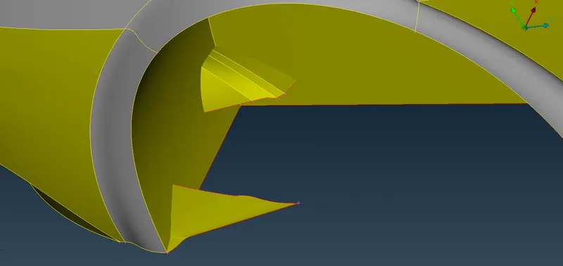
- This is the way we can choose the surfaces.
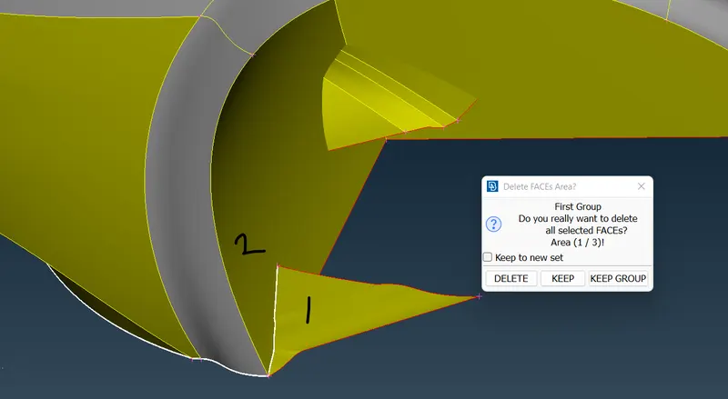
- Do the sam here and delete it.
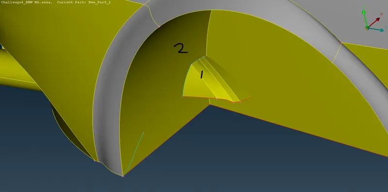
- Surfaces has been deleted.
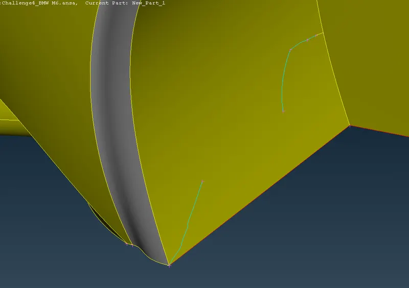
- Make CUT and delete it.
- After deleting the surface it is making red con.
- In this we create a surface.
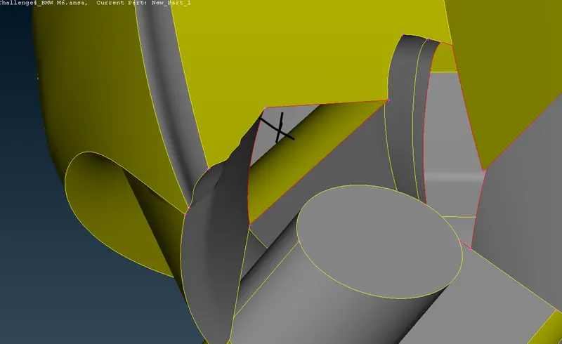
- If we observe the surface from inside there are so many red cons.
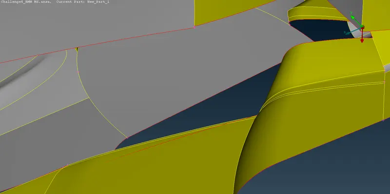
- From here we can do floor cleanup for all the surfaces whichever we want and show the final view.
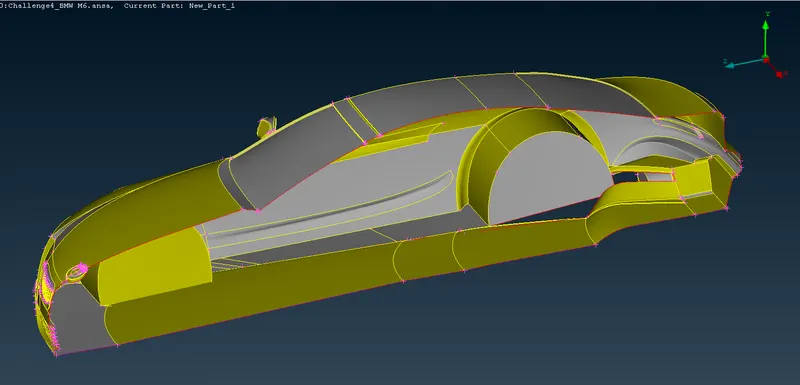
- Final view of the floor cleanup.
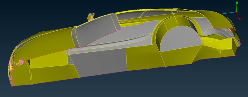
- But here we have to delete the cons2curves by using the curves->delete option.
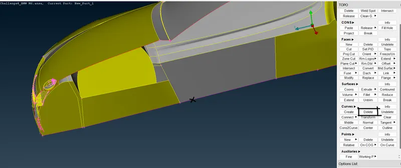
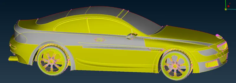
- There is no unnecessary surfaces newr tyres.
- Now go for the geometry check.
- Now it is showing only 2 intersection errors.
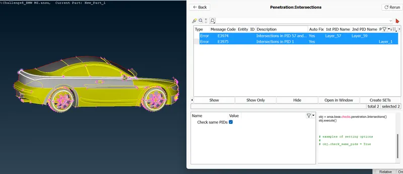
- We can delete these 2 small surfaces directly and create it newly.
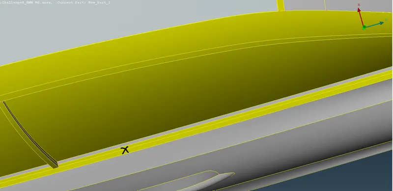
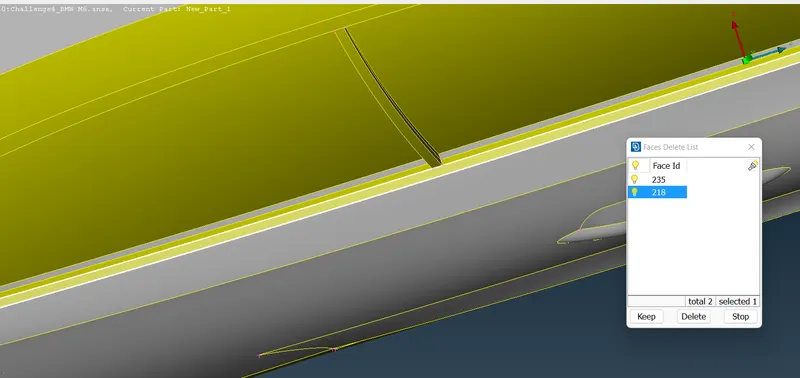
- We can delete this also, because we don't need 2 small surfaces.
- Crete some hot points in between and create a surface.
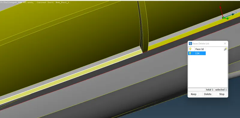
- Now we are going to clear the triple cons on the surfaces.
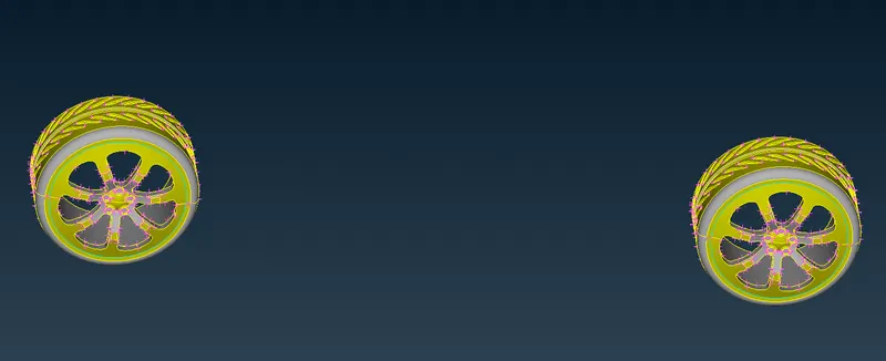
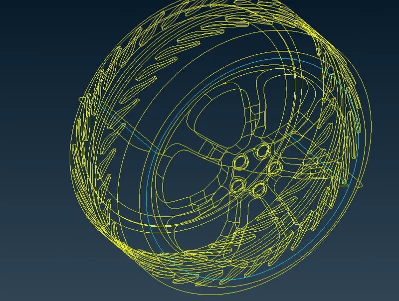
- Hide the surfaces and delete the unnecessary surfaces.
- If we see here there is an extra surface, delete it.
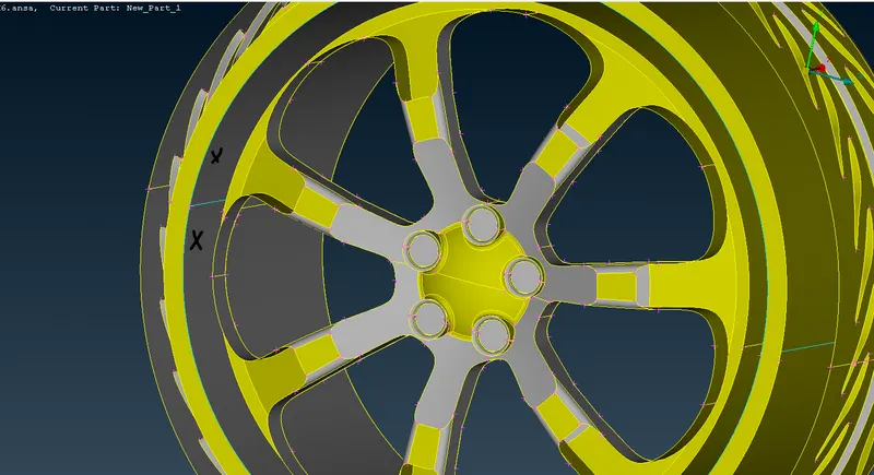
- After deleting the extra surface there is no triple cons are coming, but see the other side.
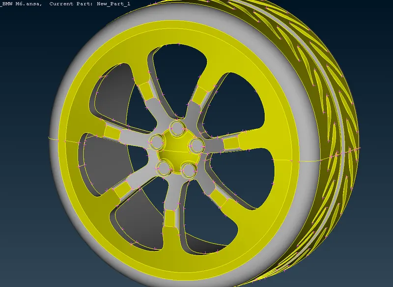
- It is creating a red con, easily we can create new surface over there.
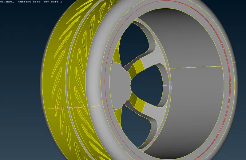
- Now it's done. Do the same procedure for the other tyre and go for geometry check.
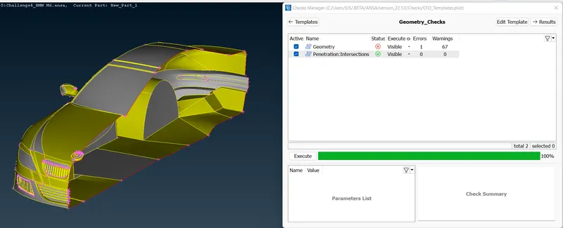
- In the geometry check there is no intersection errors but there is one surface error, check that whether we can do change or neglect.
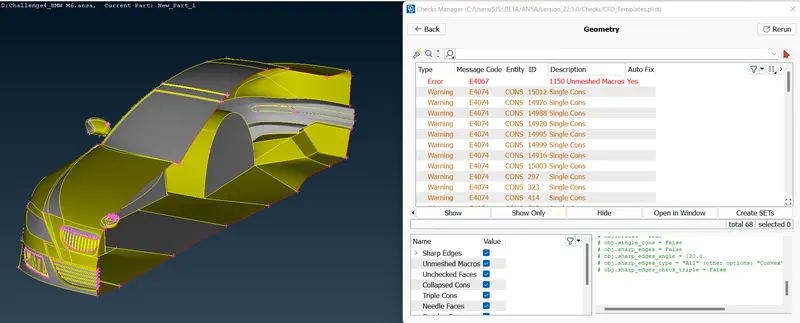
- We can directly ignore this error as it showing unmeshed before go for the meshing part.
- The single cons are only highlighting galf of the boundry, Once we did mirror of the other it will be double cons.
- BMW whole geometry cleanup has been done.
- After this assign PIDs and go for meshing.
- In this BMW we have to set the SKEWNESS and QUALITY CRITERIA.
ASSIGNING PIDs AND MESHING PART FOR BMW:
LOGO:
- Start with the logo part:
- Isolate the logo and assign PID.
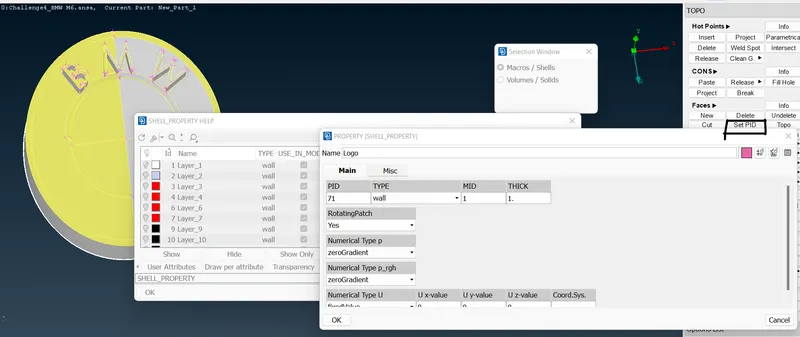
- In this BMW we are going to obey the skewness and min and max length criteria.
- So only select those and off the other elements.
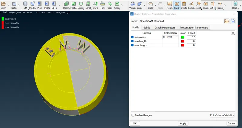
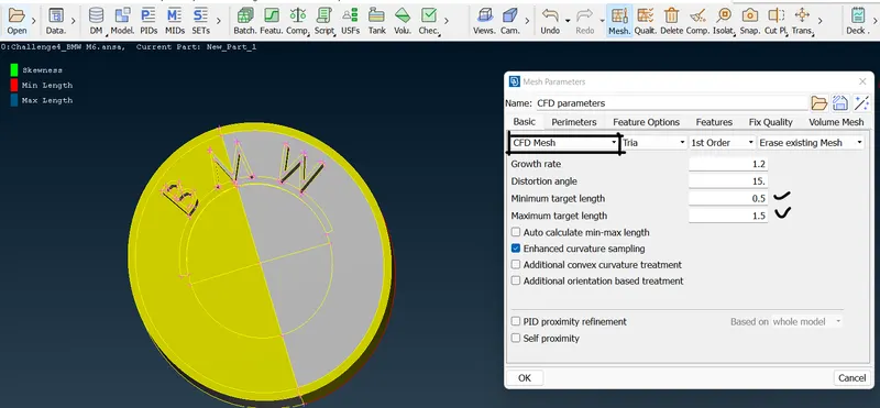
- Now go MESH PARAMETER->select CFD MESH-> and give minimum and maximum LENTH as per the target given in the challenge.
- For logo the target length is 1, so I'm giving the minimum as 0.5mm and maximum as 1.5mm->ok.
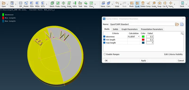
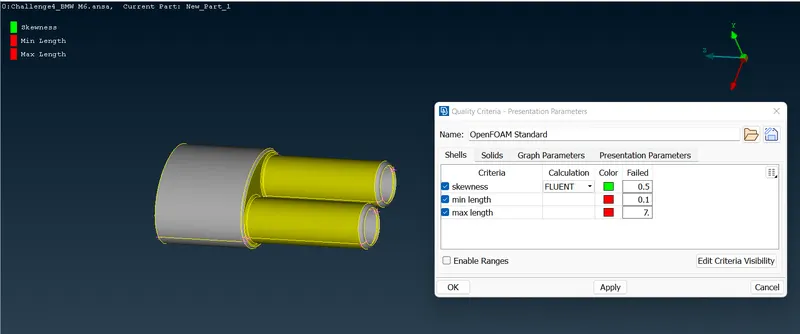
- Now go to QUALITY CRITERIA->give SKEWNESS as 0.5mm-> Minimum as 0.1mm and maximum as 7.
- Because, In the quality criteria we are giving the length based on the whole BMW target length to aviod off elements.
- For the whole BMW the quality criteria won't be change.
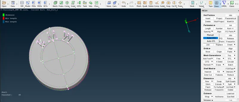
- Go to classic mesh->perimeters->spacing->auto CFD->In the perimeters and macros it will be auto filled
as given in the mesh parameter->ok.
- Go for Mesh generation->CFD->visible.
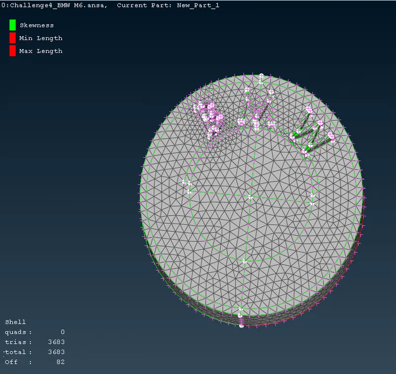
- If we see this there are 82 off elements. To clear those click on the off ->Improve->Reconstruct/Reshape->Enter till it gets 0.
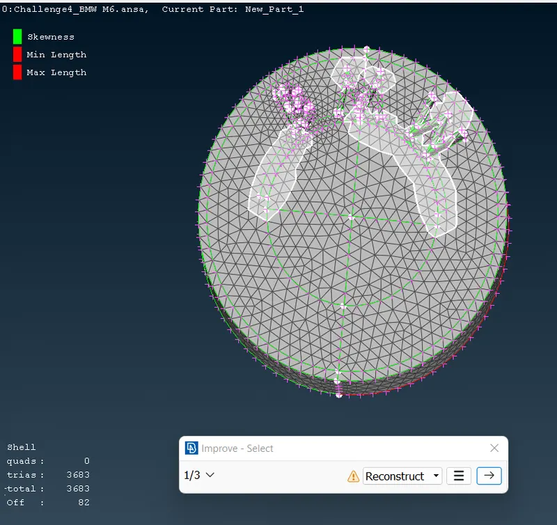
- There is no off elements now. Do the same procedure for other parts.
SILENCER:
- Start with the silencer, The target length for silncer is 3mm.
- Do the same procedure as followed in the logo.
- PID has been assigned as silencer.
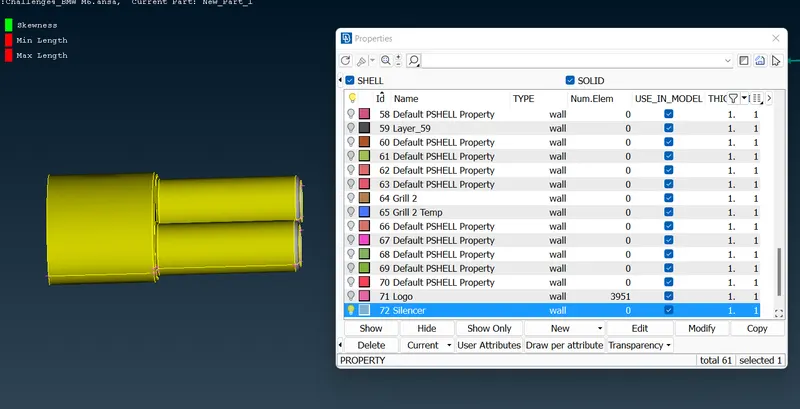
- Go to mesh parameter and I'm giving the minimum length as 2.5mm and maximum as 3.5mm.
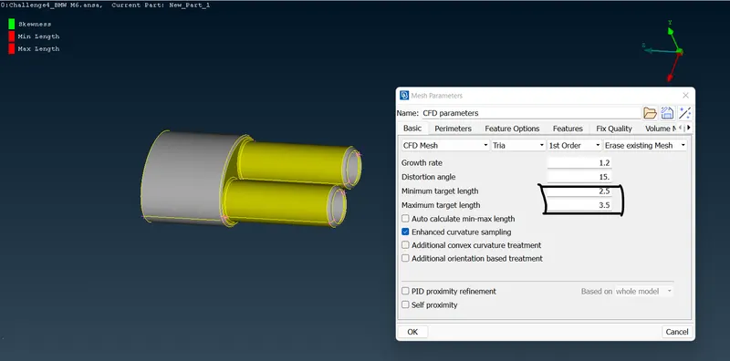
- The quality criteria I'm going to define for all the BMW parts are the same.
- Go to classic mesh do all the necessary things and select CFD->visible.
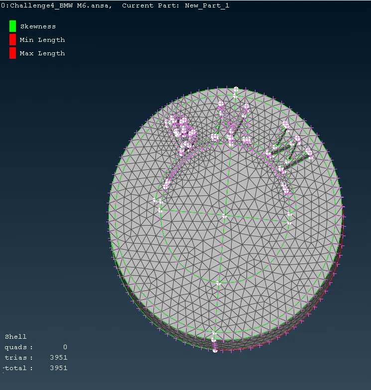
- Now it is
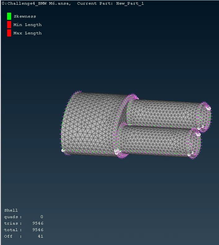
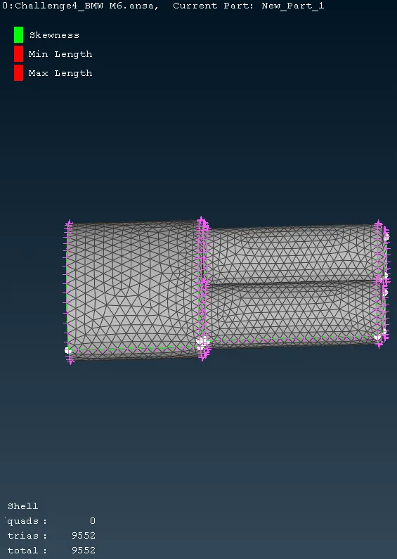
- After did Reconstruct, there is no off elements.
- Now freeze the part and go for the next to avoid collapsing the meshed parts.
Grills:
- Start with all the 3 grills. The target length for grills is 1mm.
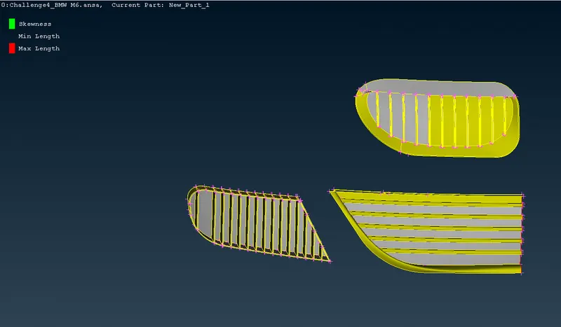
- PID has been assigned as grills.
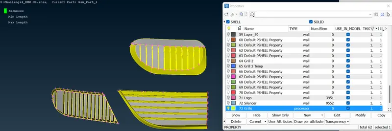
- Mesh parameter:

- Quality criteria is same like others.
- After mesh generated there are 182 off elements.
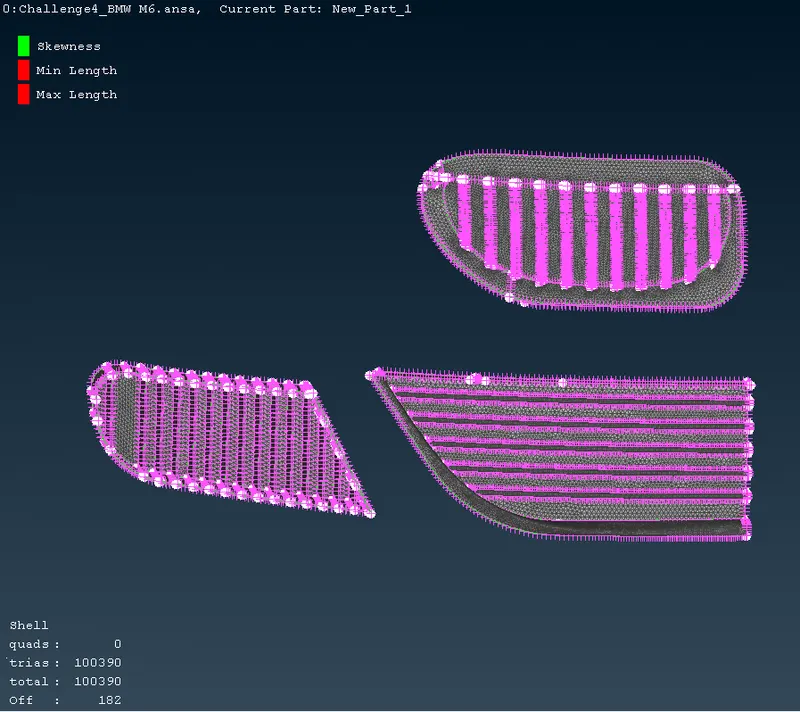
- Do reconstruct/reshape to eliminate the off elements.
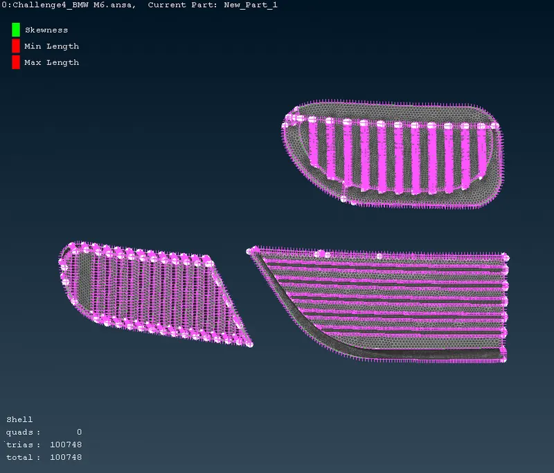
- Now there is no off elements. Finally freeze it.
RIMS & TYRES, OPTICAL REAR VIEW MIRROR AND WINDOW:
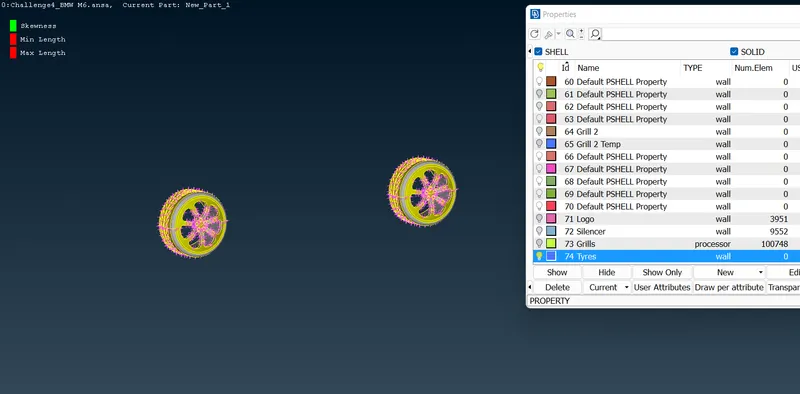
- Assign PIDs seperately and do the mesh part.
- PID has been assignes for rims and tyres.
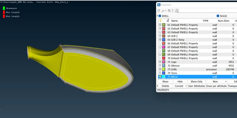
- PID has been assigned for mirror.
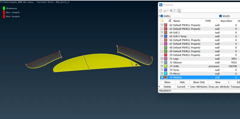
- PID has been assigned for window.
- Now we can go for mesh parameter,
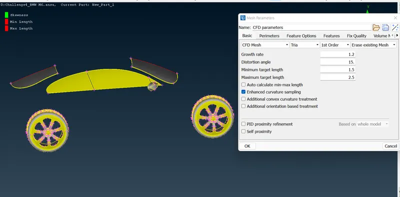
- In quality criteria give ok as it was already defined.
- After CFD mesh there are 206 off elements.
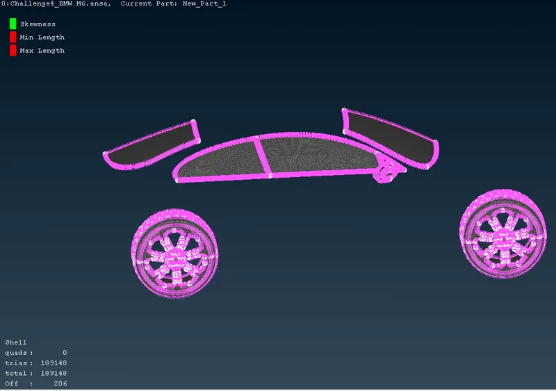
- Do reconstruct/reshape,
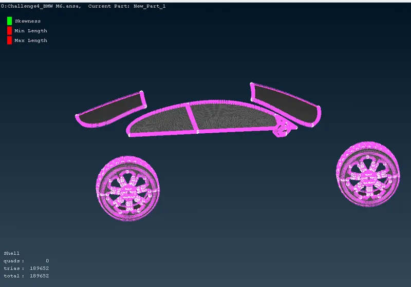
- After a single reconstruct the off elements are meshed properly.
LIGHTS:
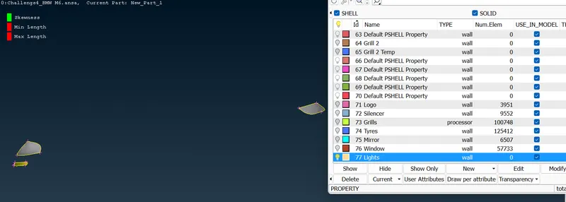
- For lights the target length is 4mm.

- PID has been assigned.
- Mesh parameter,
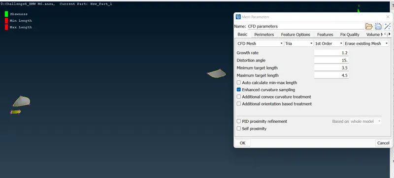
- There is no off elements, mesh has been perfectly done.
- Now do freeze.
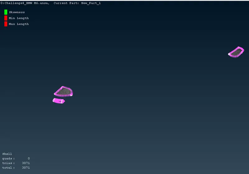
BODY:
- Only body is remaining, The target length for body is 3mm.
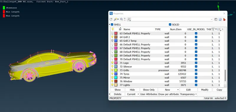
- PID for body has been assigned.
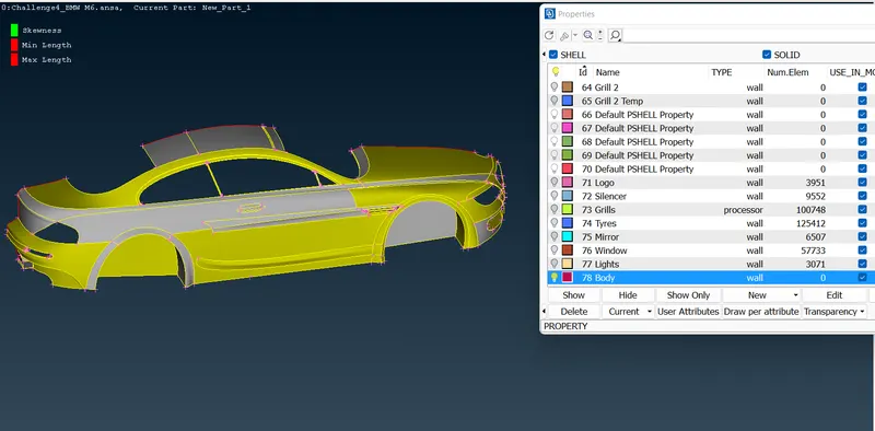
- Mesh parameter,
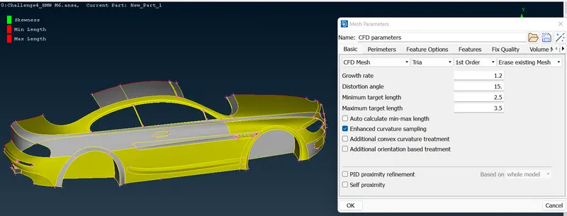
- There are 376 off elements, do improve.
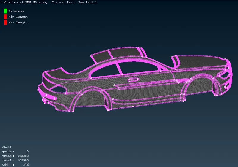
- Proper mesh with no off elements.
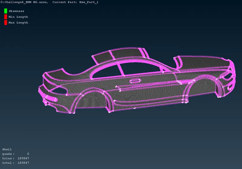
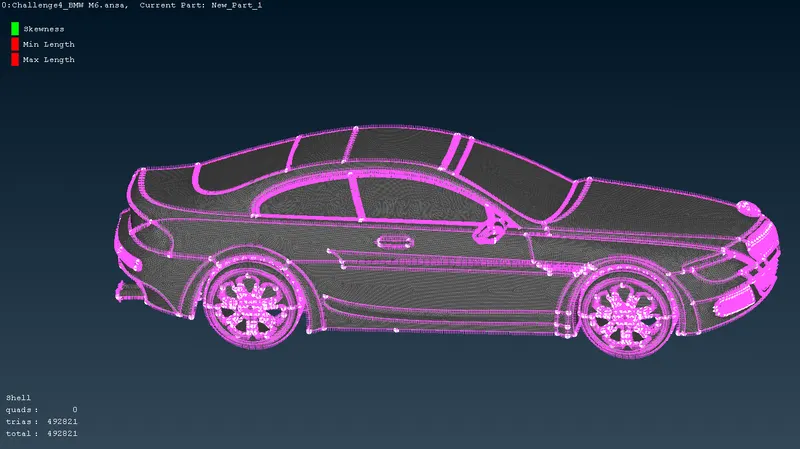
FINAL HALF BMW VIEW:
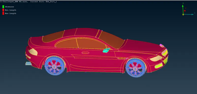
- PID view:
CREATING ANOTHER HALF:
- Now we are going create the BMW other half part using the TRANSFORM tool.
- Before that we have to hide the logo, because it is single unit part for other half also.
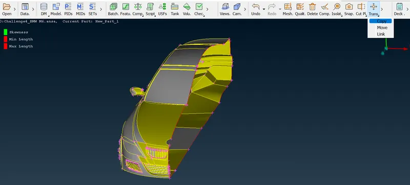
- Select entity as full body and do middle click.
- It will ask for the copy method, select SYMMETRY and click MIRROR 3 POINTS PLANE.
- Now select any 3 hot points on the red coon boundary->give ok in the popup box->finish.
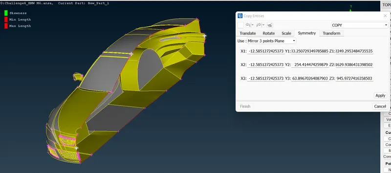
- Other half has been created.
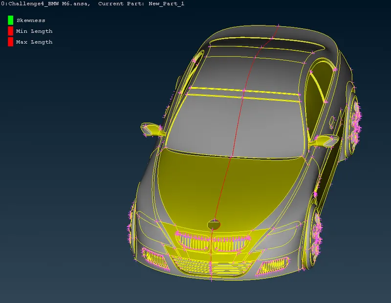
- Now switch on logo and do TOPO click.
- Still it is showing one red coon, see closely what is that,
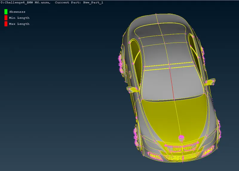
- There are 2 coons are present, so here use we can delete that one surface and create it or else we can
use cons->paste->select both the coons->middle click.
- Now it's done.
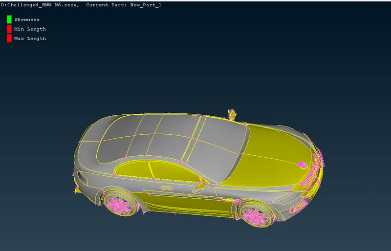
- After going to mesh, it is showing some off elements and unmeshed parts.
- For unmeshed parts we can go for free mesh generation.
- For off elements we have to do improve.
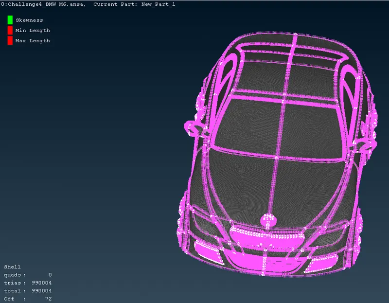
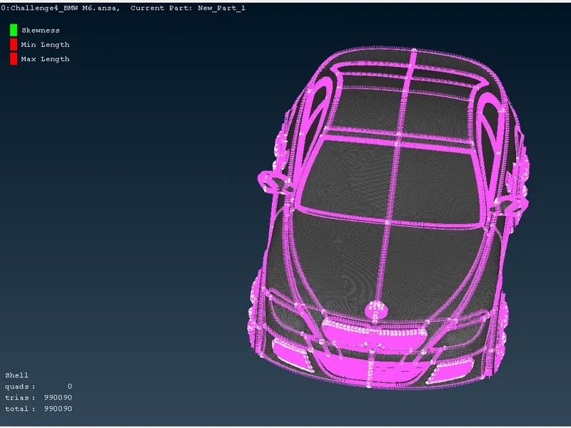
- Finally we have cleared all the off elements.
CREATING WIND TUNNEL:
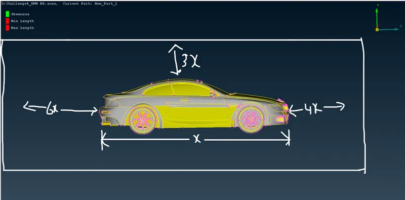
- We have to create a wind tunnel based on the image.
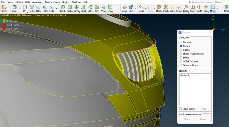
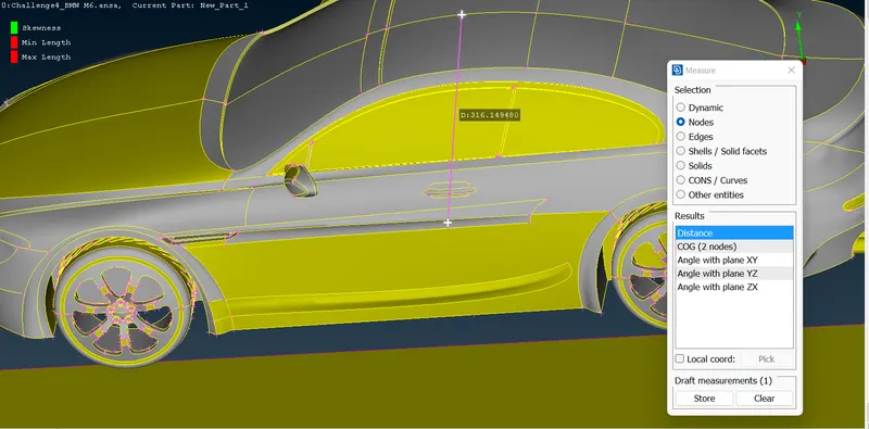
- Go for the measure tool to find the X distance.
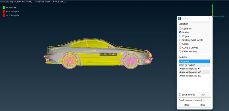
- X value is 1307.87.
- TOPO->POINTS->RELATIVE->in DZ give half of the X value 655 in the negative value.
- Select nodes->click node in the front as I mentioned as X->give value (-655)->ok.
- The point has been created exactly in the middle.
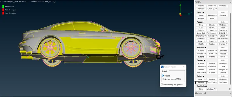
- Again I'm selecting the point which newly created and middle click.
- Now to create the point in the down, give any value ( -500 I'm giving) which should not intersect the tyres.
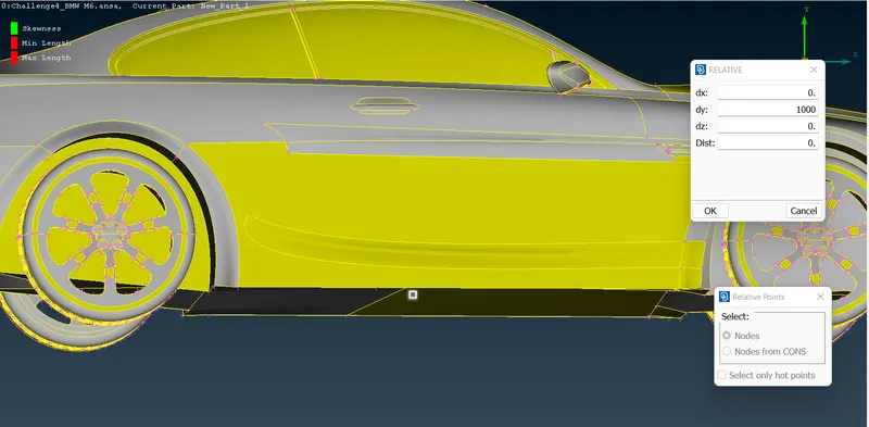
- It has been created. Do the same for others with their respective distance.
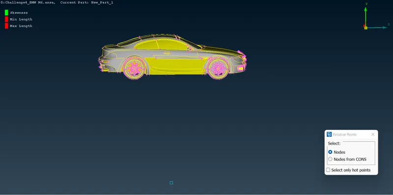
- To create point on the front select the lower point-> middle click-> give dz=5895 (655+5240) in the positive value.
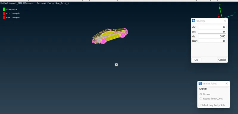
- It has been created.
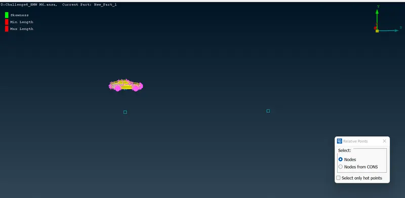
- For back side the dz value is 655+7860=8515 in the negative value.
- It has been created.
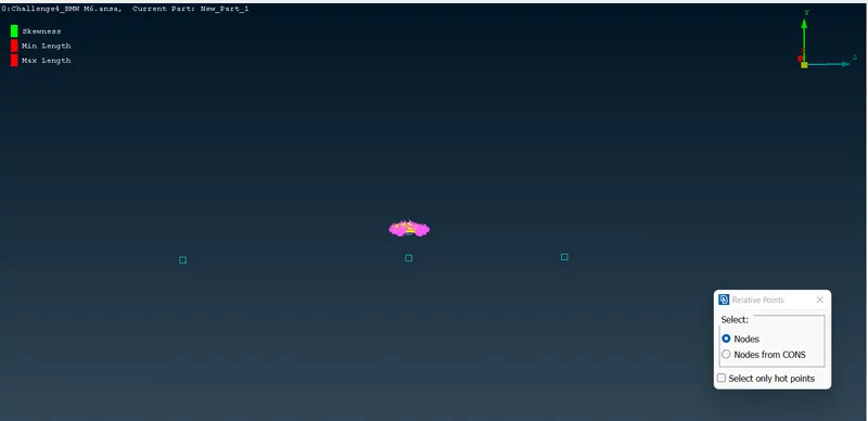
- For sides I'm going to take X value.
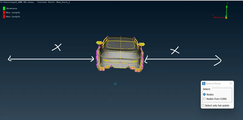
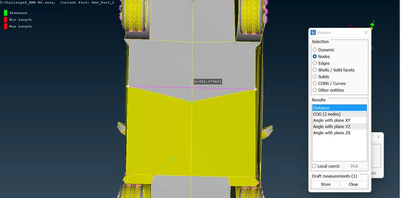
- This is the length of the down surface.
- Now I'm gonna select both the points to create X direction points in the positive and negative values.
- The value we need to use is 230 from the half length of the lower distance and the X car distance.
- 230+1310=1540.
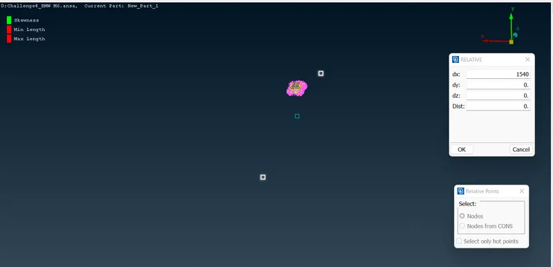
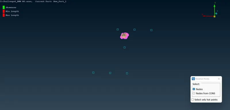
- It has been created and now give the same negative value dx=-1540.
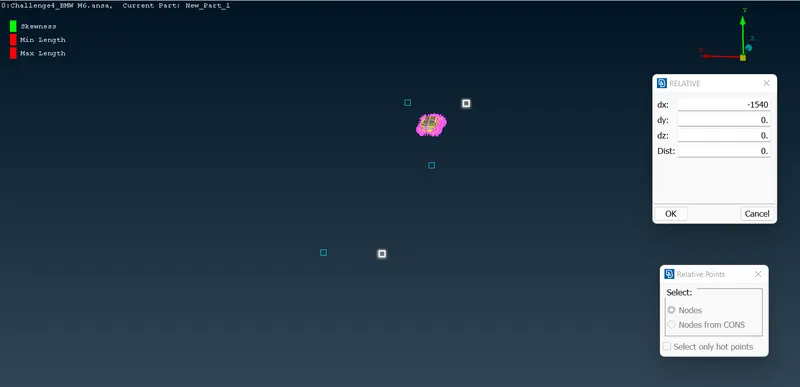
- Now it's done in the lower part.
- Do the same procedure for the upper side also.
- Create a hot point exactly in the centre of the upper surface and go to relative create a point like we did before.
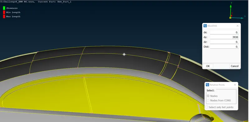
- The distance is 3X=3930 in the dy direction.
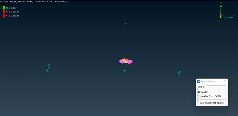
- Now create a coon and surface in the bottom points.
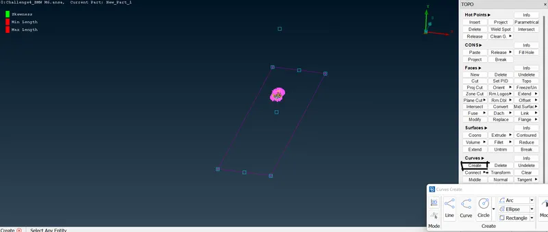
- TOPO->CURVES->CREATE->SELECT THE POINTS AND MIDDLE CLICK.
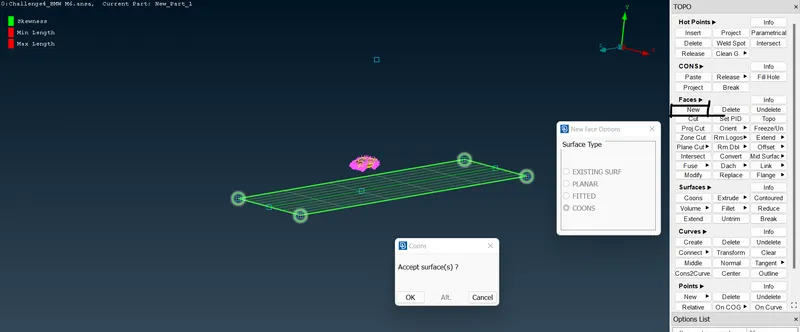
- TOPO->FACES->NEW->SELECT POINTS->MIDDLE CLICK->CREATE SURFACE.
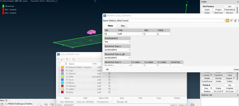
- Automatically it will ask for PID, and create a new PID.
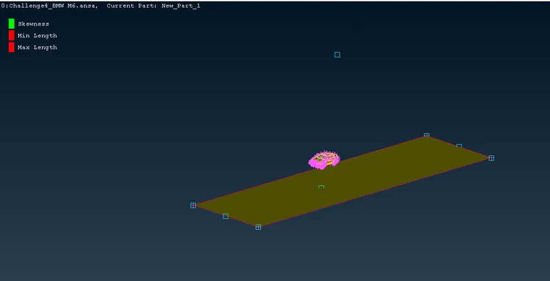
- Final View:
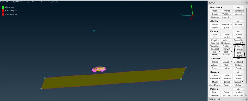
- To copy the same face for the upper point go to TOPO->FACES->OFFSET->FACES.
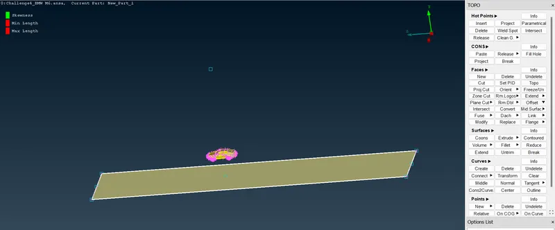
- Click on the surface and middle click.
- It will ask the upper value to create a surface.
- Give negative value as the direction arrow shows the other direction.
- The value is 3930(3X)+330(car Y length)+500(bottom surface distance from the car)=4750.
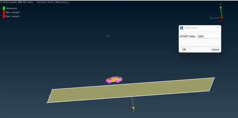
- The surface has been created exactly on the point which created on the upper side.
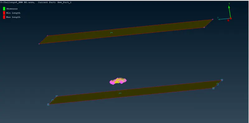
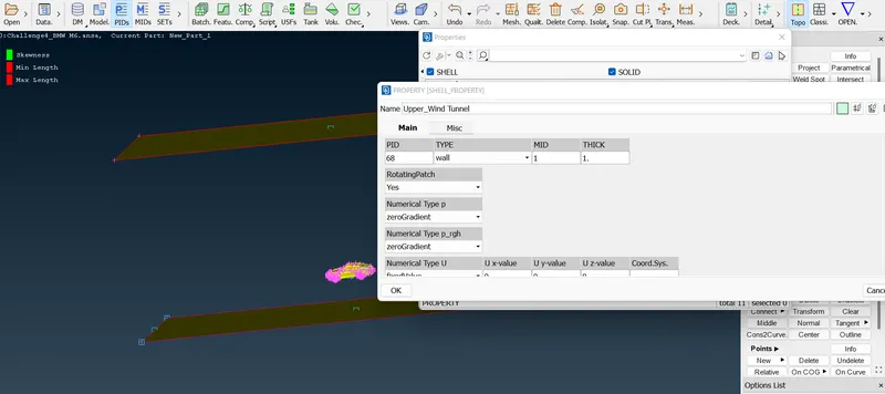
- Assign PID as upper wind tunnel.
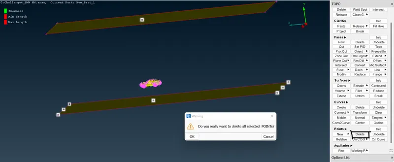
- Delete the points which we have created.
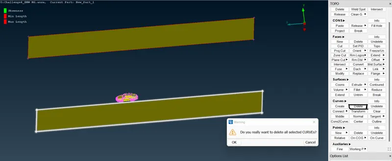
- Delete the curves also.
- Now create the side surfaces.
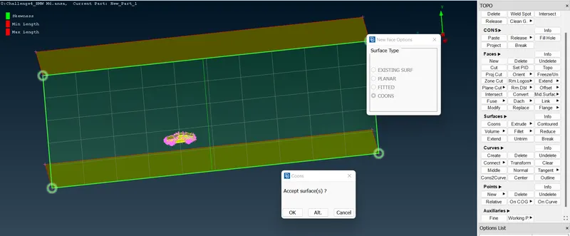
- Automatically it will ask to create PID, create it.
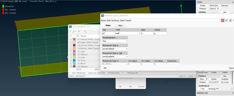
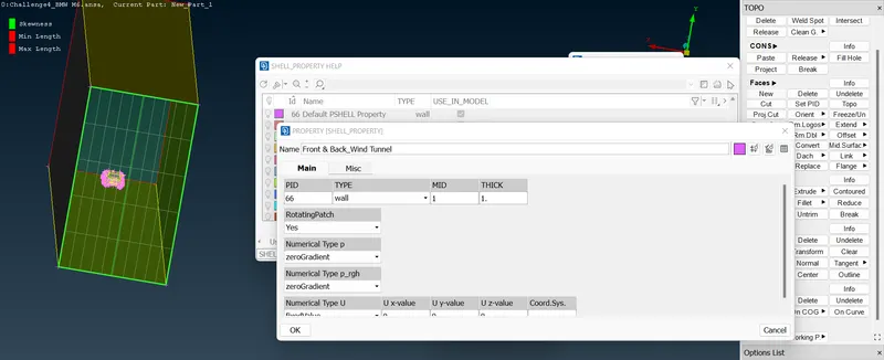
- Create new PID and assign the same for both front and back side tunnels.
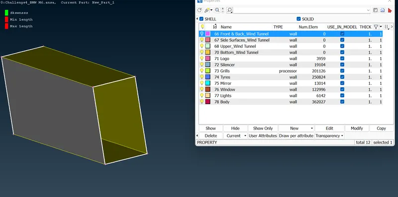
- PIDs for all the tunnels has been done.
WIND TUNNEL MESH:
- In the mesh parameter I'm going to give minimum length as 15 and maximum as 25.
- Because there is no target given in the challenge.
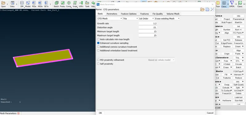
- Go to classic mesh->perimeter->spacing->auto CFD->mesh generation->CFD->visible.
- Meshing is completed for the bottom surface tunnel.
- Do the same for upper surface tunnel. But change the length minimum as 90mm and maximum as 110mm.
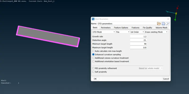
- Mesh done for upper surface also.
- Here we are changing the distance depending upon the side wind tunnels.
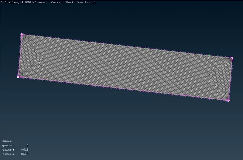
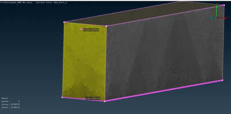
- We have changed the limits to gradually increase the mesh.
- Because of the wind tunnel size.
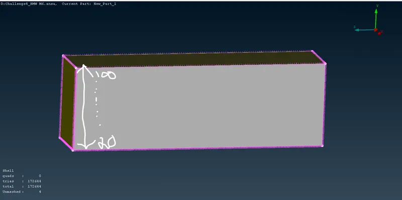
- For the sides we are going to use MANUAL CFD to gradually increase the range from the lower to the higher.
- The range we are going to define is from 20 to 100. Before giving an ok we have to select the direction from which should start.
- For that only we have used the smaller range to the bottom surface and higher range to the upper surface.
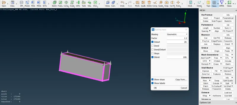
- Reference view.
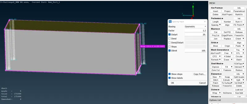
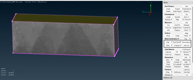
- Go to spot mesh and visible.
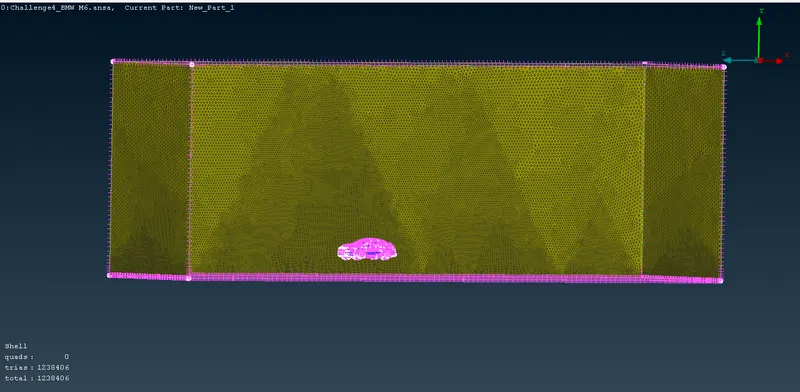
- Final mesh view for WIND TUNNEL..
- Used the measure tool to show the gradual limit.
OUTPUT: