Week 3 Challenge : CFD meshing on Turbocharger
AIM:
- The main aim of this challenge for the given model is,
(1)To check and correct all the geometrical errors.
(2)To create and assign PIDs for each part of the turbocharger.
(3)To perform surface mesh with the given target lengths as per PIDs.
(4)To perform volumetric mesh for the required volumes.
PROCEDURE:
- Import geometry from file->open->file location->challenge3.ansa
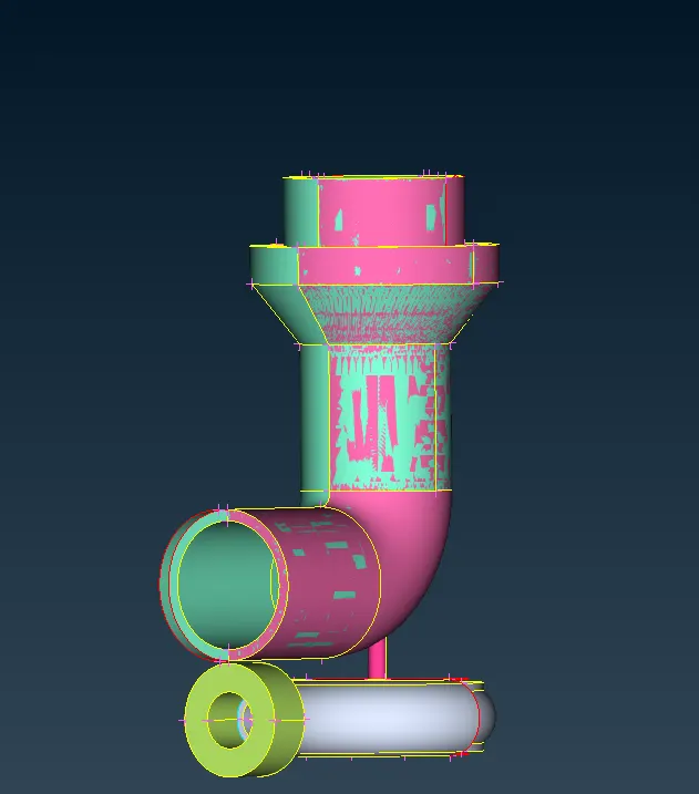
- Enable labels to show the tool's name.
- Enable only this overlapping PID and delete it universally.
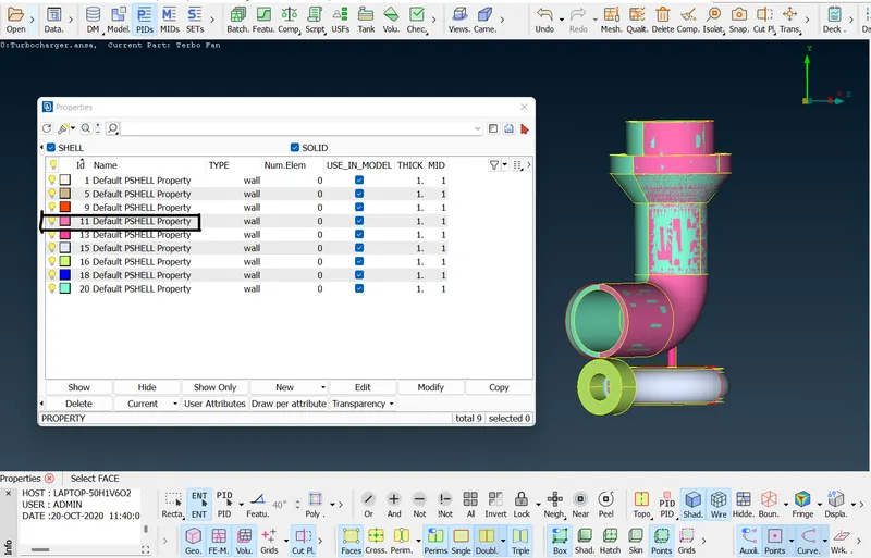
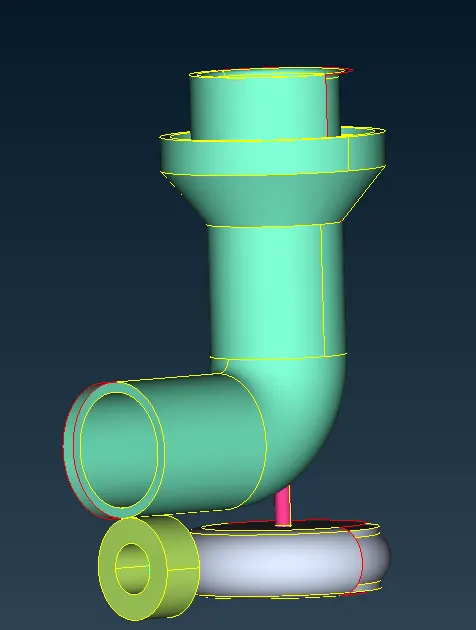
- This is the view in which we are going to make the geometrical corrections.
- First see the red cons by only switching on a single con tool.
- To see the single cons alone we have to use ctrl+shift.
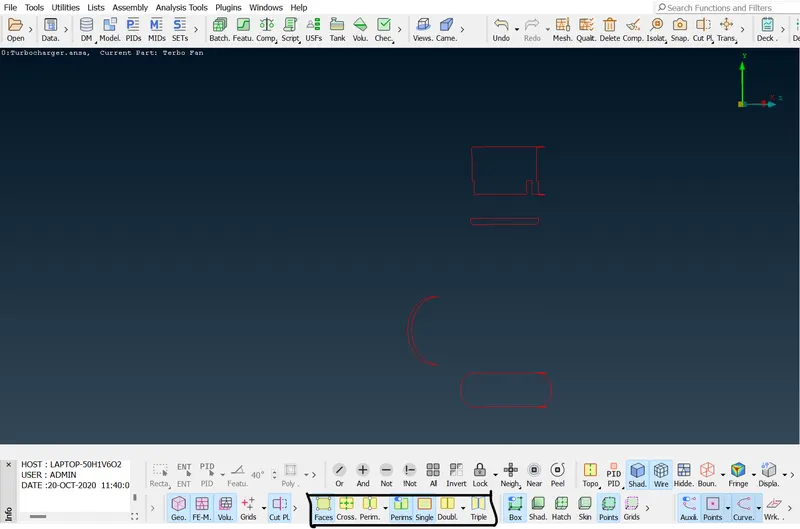
- First, focus on the red cons and solve them appropriately.
- This is the unwanted surface that needs to be deleted.
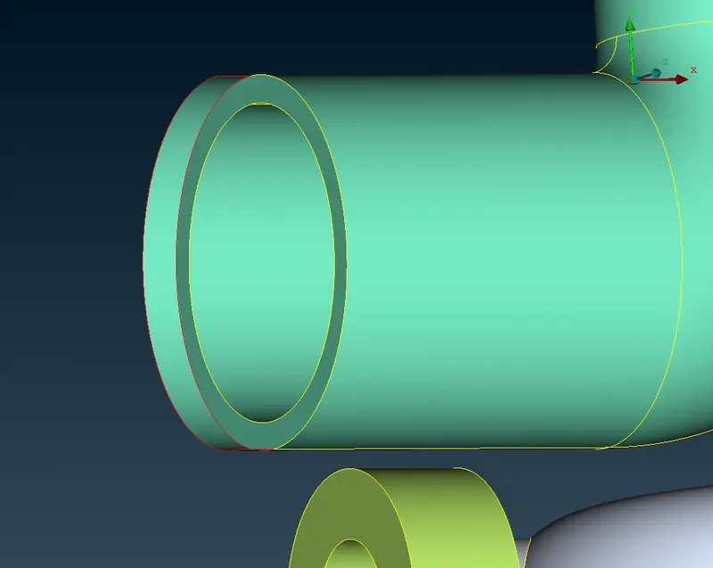
- Deleted view.
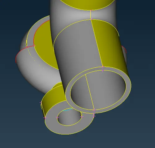
- Focus on these red cons in the beginning.
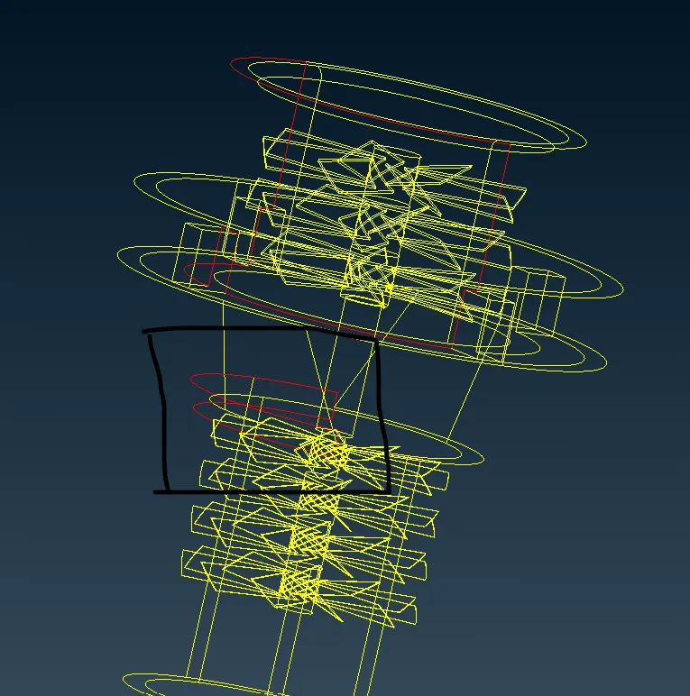
- Do intersection for these surfaces and delete the red con.

- The red con was removed but the connected surfaces are not proper.
- Use the cut option and delete the surface there.
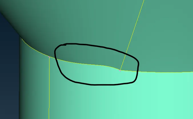
- Delete the surface and create it again.
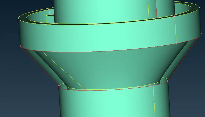
- The surface pre-model has been perfect.
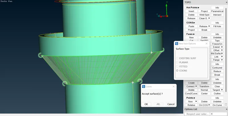
- Other red cons:
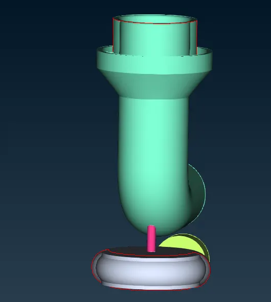
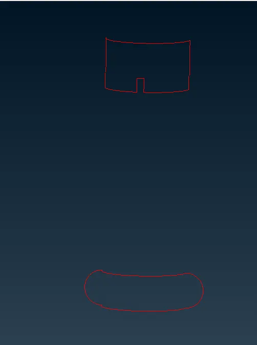
- Solve upper surface. Use the transform option to create mirror cons between the hot points.
- TOPO->CURVES->TRANSFORM->SELECT THE SURFACES->DO MIDDLE CLICK.
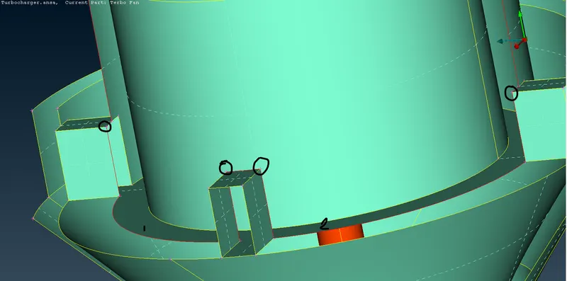
- Check before creating the surfaces.
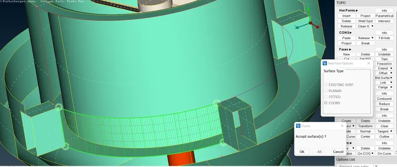
- If we observe clearly these cons, that newly created transform cons have made extra con.
- So delete that cons after created.
- TOPO->CURVES->DELETE.
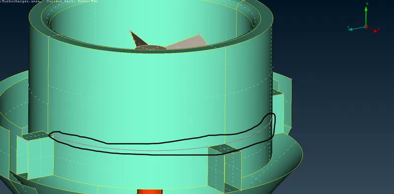
- Now the newly created surfaces are perfect.
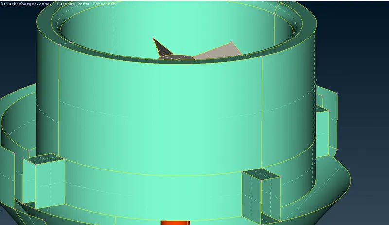
- This is the only con that is remaining on the outer surface.
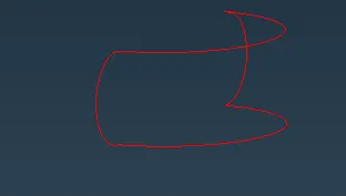
- Insert a hot point in the middle and do transform to create the same surface which is presented on the other side.
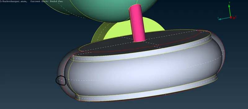
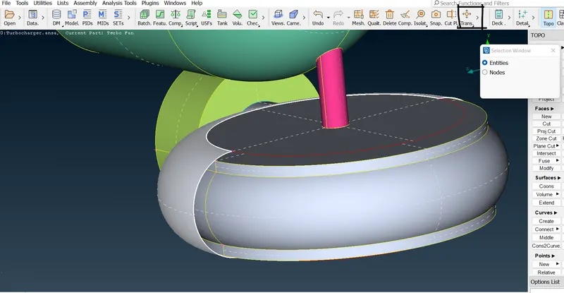
- Select Transform->copy-> entity as which we need to mirror the surface->middle click.
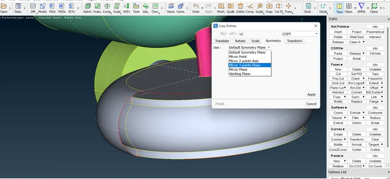
- After doing the middle click this setup box will come, go to symmetry and select mirror 3 points plane.
- Select these 3 hot points->give apply and finish.
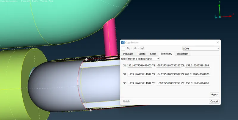
- The surface has been created successfully, Finally do TOPO.
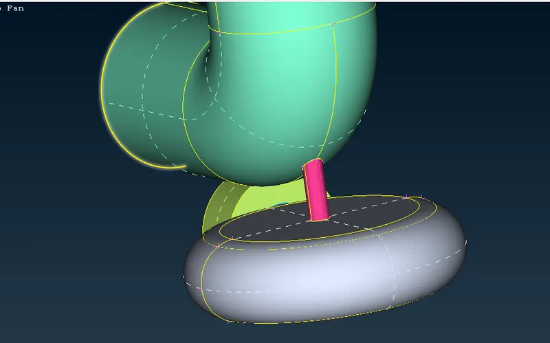
- Now do a geometry check for the whole surface and see the other con errors.
- Check intersection errors.
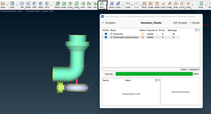
- These are the intersection errors that need to be resolved one by one.
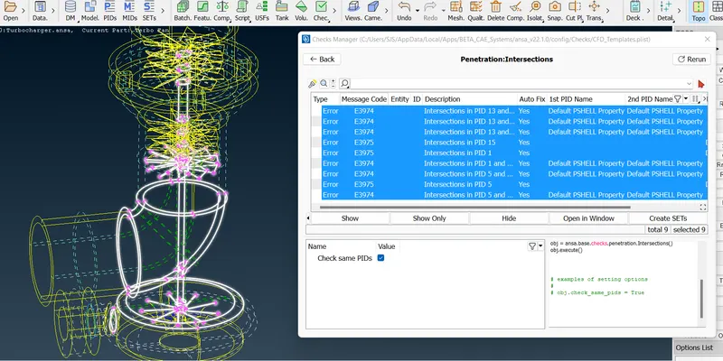
- Most of the errors are showing in the shaft. So clear this geometry error and go for next.
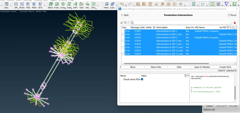
- See whether these 3 cons are needed, If not delete them.
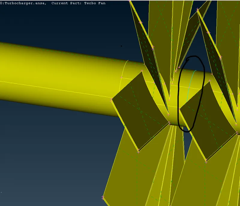
- If we see this, the inside surface is not required. So delete it.
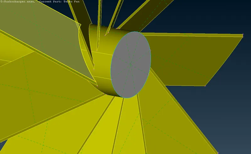
- After deleting the surface, the 3cons are not showing. So technically we can delete the inside surface.
- Do the same thing for other same cons.
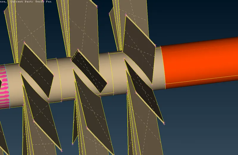
- If we clearly observe the overlapping surface, the shaft is connected inside the other.
- So delete the overlapping surface and make it separate.
- Project the shaft and delete it.
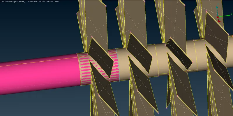
- Now we can delete the surface alone after projecting.
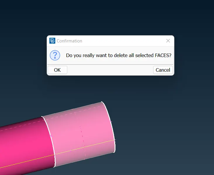
- All 3 cons are deleted successfully in the upper shaft.
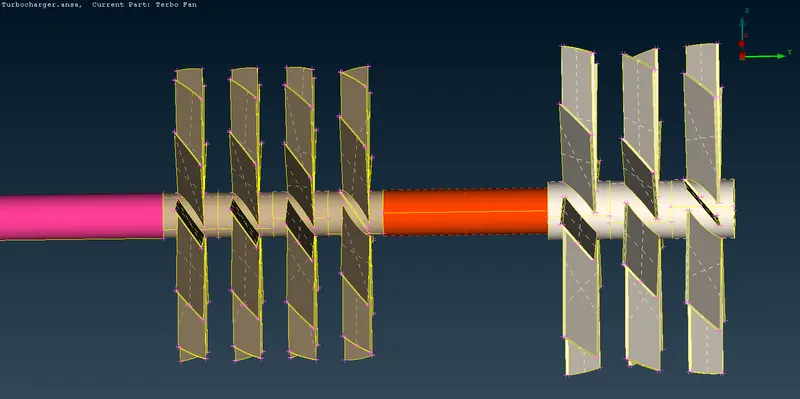
- In the upper rotor shaft we have to delete both the inside surface and create it newly.
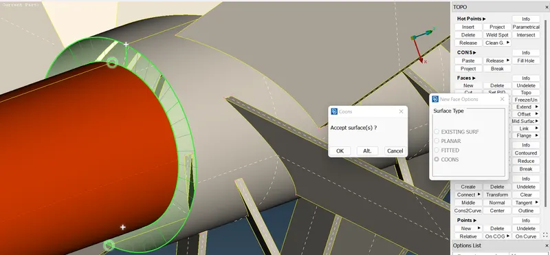
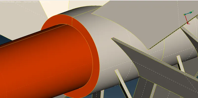
- The surface has been created in the name of the shaft.
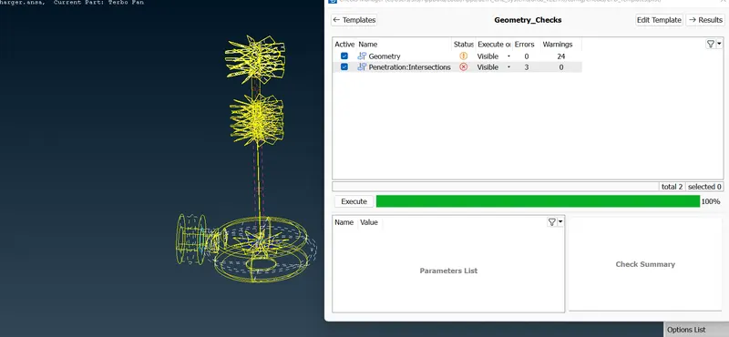
- Do geometry checks and see other errors.
- Now it is showing only 3 intersections and 24 warnings. Try to clear all the errors.
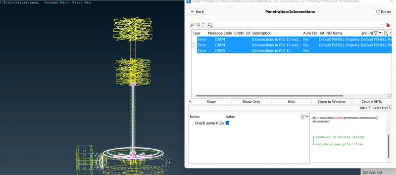
- Now it is showing only on the lower face.
- In the whole part also the same errors are showing.
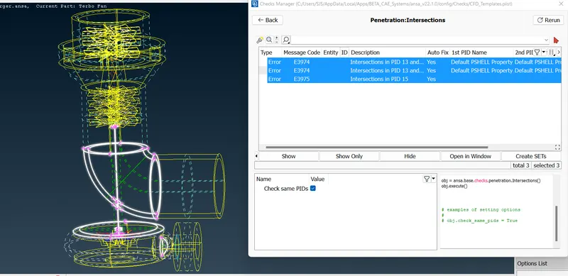
- This is the main error that is connecting most of the parts.
- Delete the overlapping.
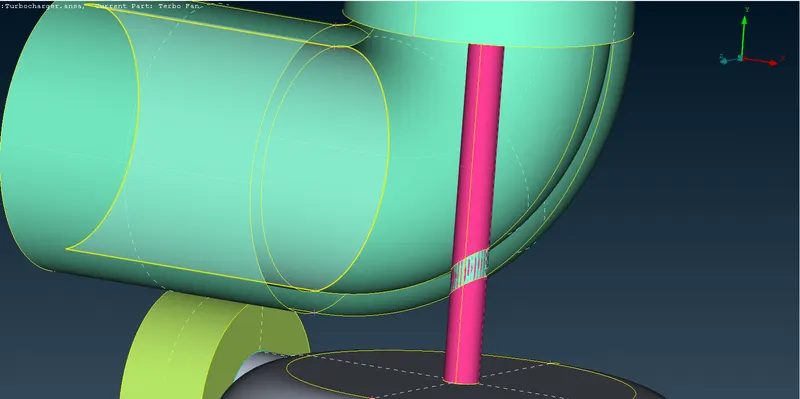
- Now project the surfaces and delete the middle unwanted surface of the shaft.
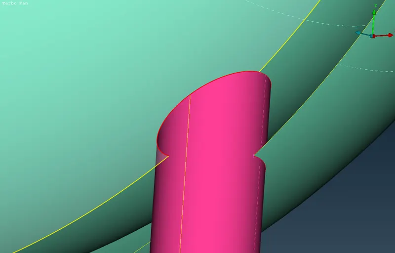
- It is projected and now delete the middle surface.
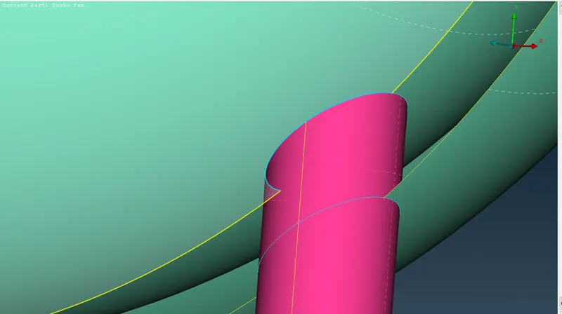
- Correct view.
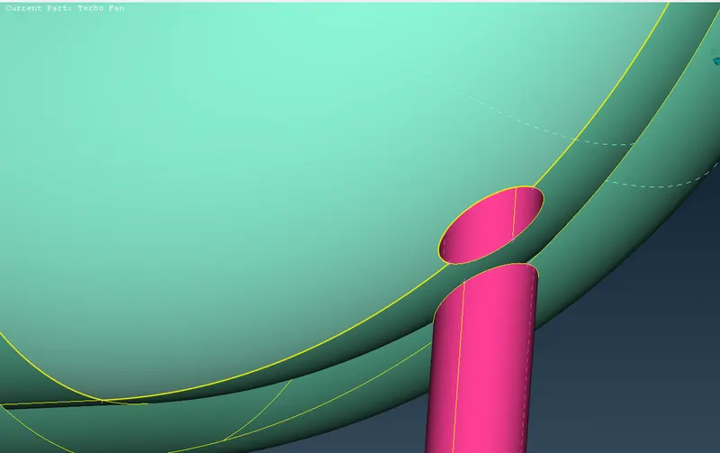
- Remaining errors:
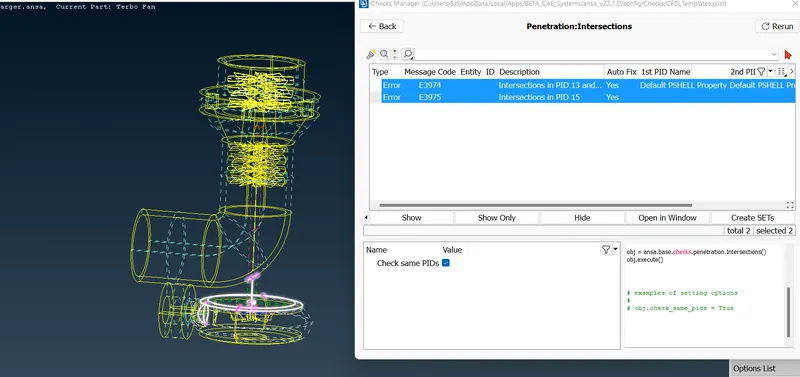
- If we observe the errors it is showing the intersection errors and single cons.
- Remove those errors.
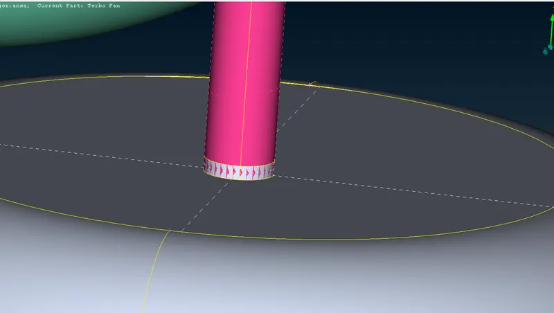
- Project the surface and delete the middle surface to remove the error.
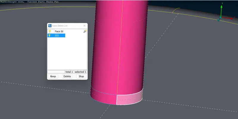
- Now it is removed.
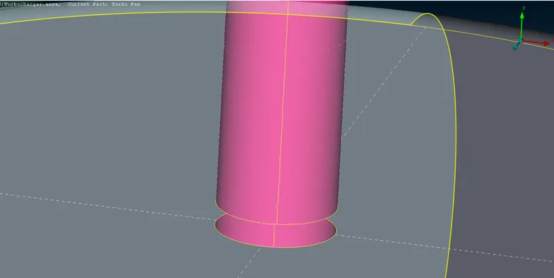
- let's hide this surface and do the changes inside the compressor.
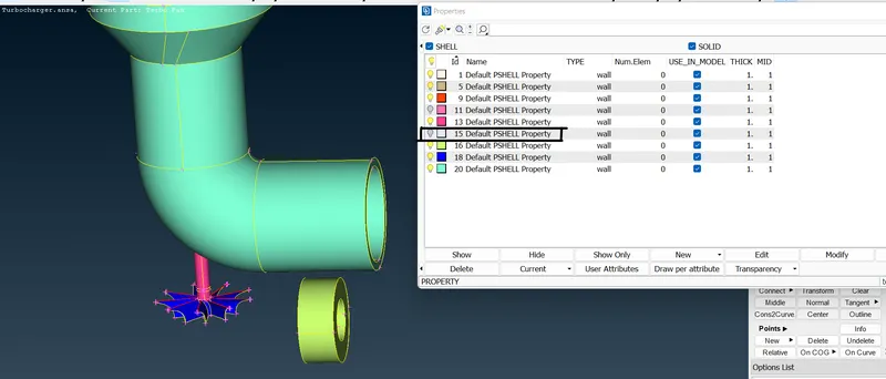
- Deleted the 3 cons and red cons.
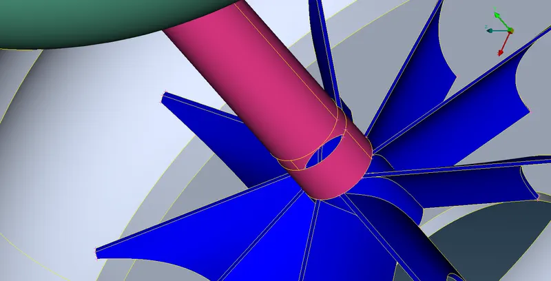
- Still it is showing one intersection error.
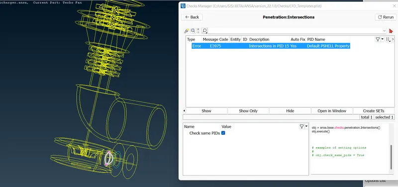
- This is the unwanted surface that is showing an intersection error. So, let's delete it.
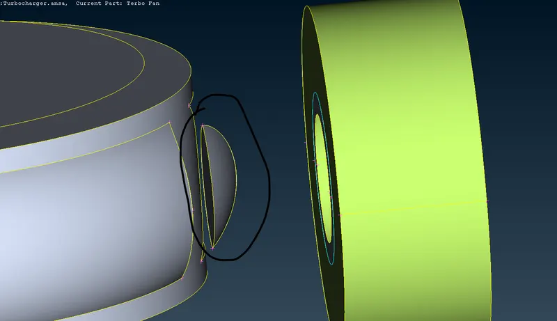
- Cleared all the intersection errors.
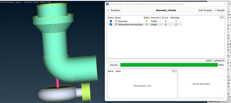
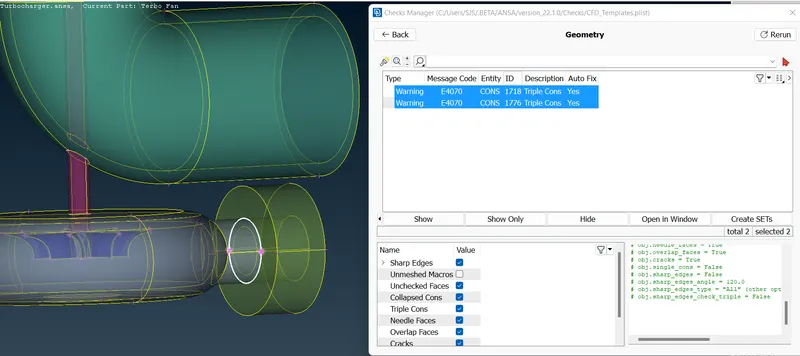
- Check the warnings, if they can be removed try to remove them.
- Here it is showing triple cons because 3 surfaces are joining here. So we can't delete this.
- Now give naming for each part as given in the challenge.
- Click the color->right click->edit->change the name->ok.
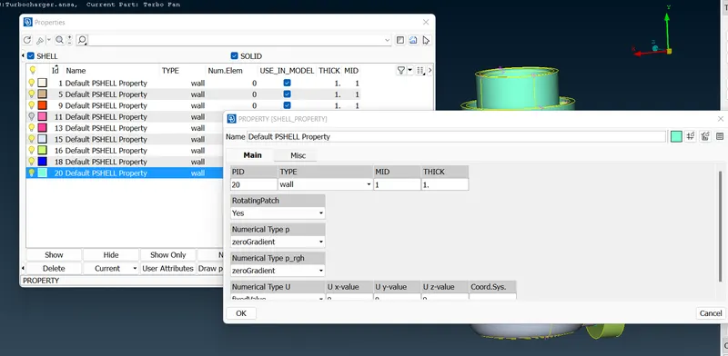
- Change the shaft color to pink. Click pink->apply->select the small shaft->middle click.
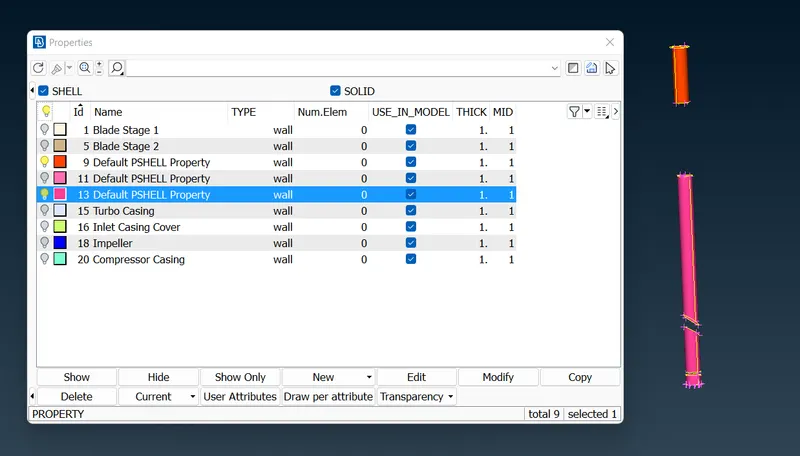
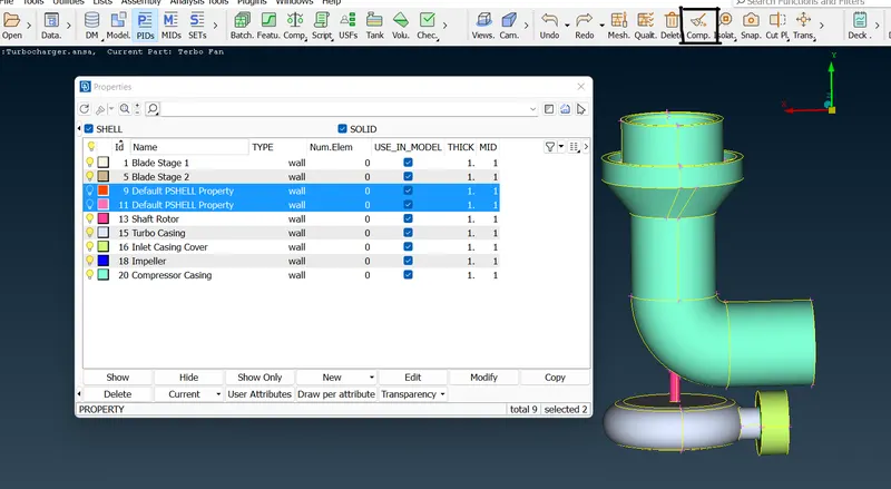
- Naming has been done and delete the PIDs which don't have parts using the compress tool.
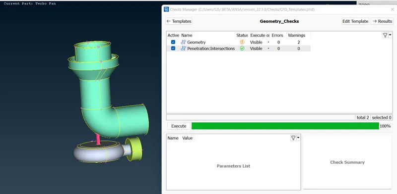
- All intersections and warnings are cleared. Finally, do check the manager.
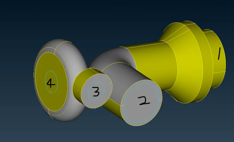
- Close the inlet, outlet, and other open surfaces before meshing.
- Go for the meshing part. These are the given target mesh length.
- Blade stage-1 = 1 mm
- Blade stage-2 = 1 mm
- Impeller = 2 mm
- Shaft rotor = 1 mm
- Turbo casing = 5 mm
- Compressor casing = 5 mm
- Inlet casing cover = 5 mm
- Do mesh one by one,
- In this case I'm going to do classic mesh for these 3 parts at the same time. Because the target length given for these parts is the same.
- Do not forget to close the holes before meshing.
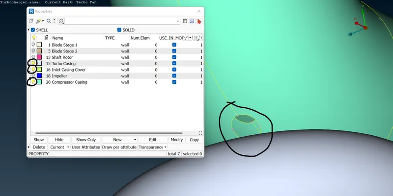
- Go to classic mesh->perimeter->length->give perimeter and macros as 5mm for these parts.
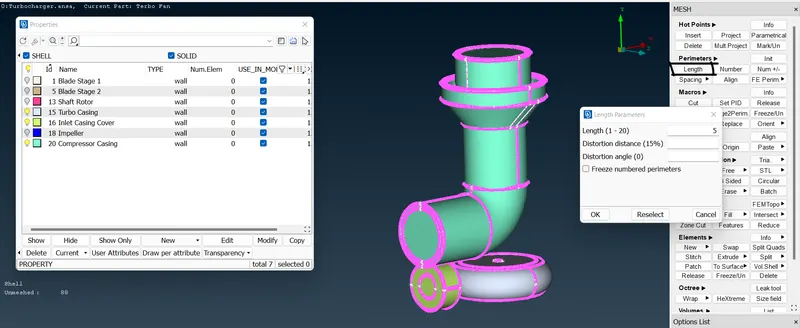
- Now click spot mesh and select visible to generate the mesh.
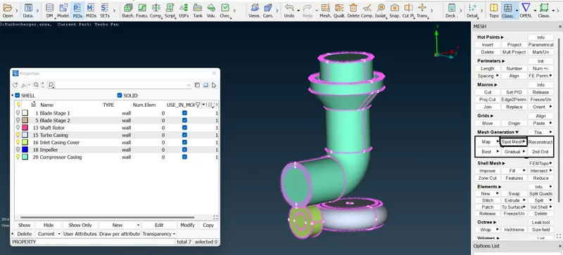
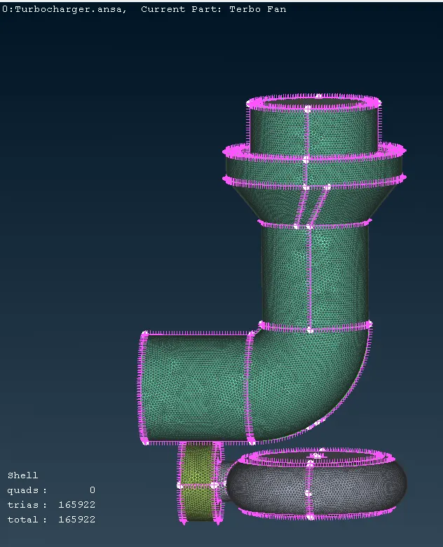
- Spot mesh output for castings.
- Do like this for other parts of the turbo with their given length.
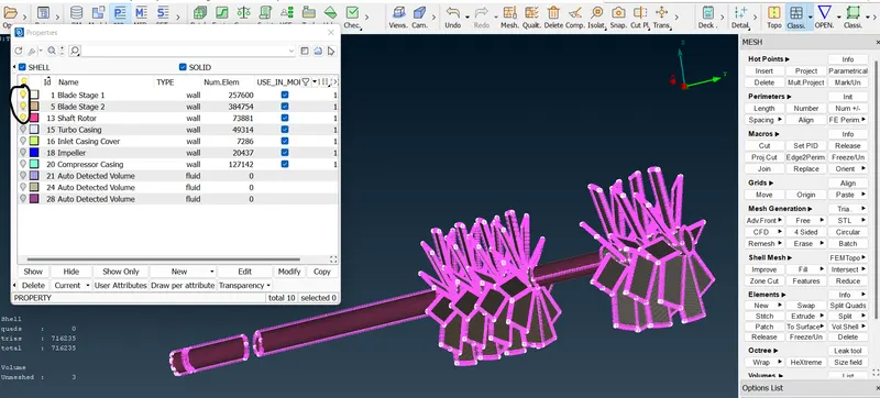
- Select blade stages 1,2 and shaft rotor->give mesh length as 1mm.
- Select spot mesh and visible.
- Output:
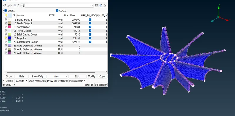
- For impeller give 2mm and do spot mesh.
- Output:
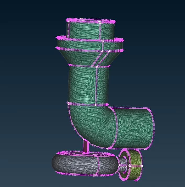
- Overall surface mesh output:
- Now start with volume mesh.
- Volume mesh->volumes->define->volume detection popup will come->give ok.
- After giving the ok volume box will come. Select internal surfaces which are needed and delete others.
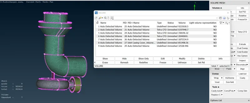
- After deleting unwanted volumes, these are remaining.
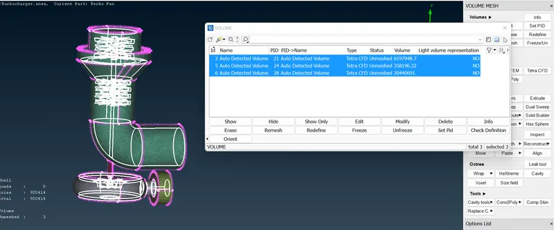
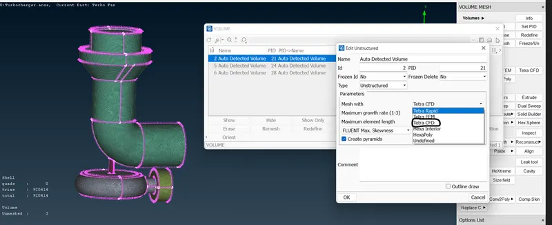
- Double click on unmeshed status and select TETRA CFD or TETRA RAPID and click ok.
- Do like these for other volumes.
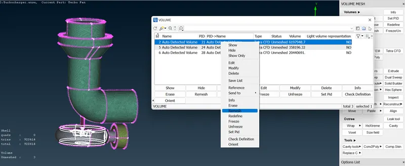
- Do right-click and select re-mesh for each of them.
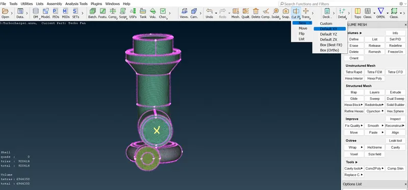
- To see the volume mesh inside the turbo model,
- Go to the cut plane option->new->default XY->select anywhere between the marked X in the model.
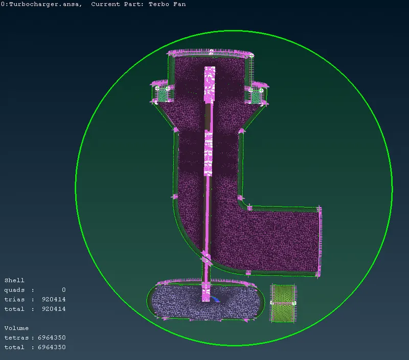
- One popup box will come, In that create a new part and give ok.
- It will show the inside half part of the volume mesh.
Final result:
Learning outcome:
- Learned usage of the intersection option.
- Learned the difference between project and cut options.
- Learned the mesh types and the different usages.
- Learned ANSA tools in a deep way.
Conclusion:
- All the geometrical errors, intersection errors and most of the warnings have been resolved.
- After all of that target mesh length and volume mesh have been created as given in the challenge.
- Final model has been attached https://drive.google.com/file/d/1-RttU53lcxepyOBdu6eW0OtV6L6W7QLj/view?usp=sharing.