Project 1 : CFD Meshing for Tesla Cyber Truck
AIM:
- To perform mesh for the given TESLA CYBER TRUCK model,
- Check and solve all the geometrical errors,
- Assign appropriate PIDs,
- Perform meshing with an element quality criteria.
PROCEDURE:
- Import geometry from file->open->file location->project_cyber truck.ansa
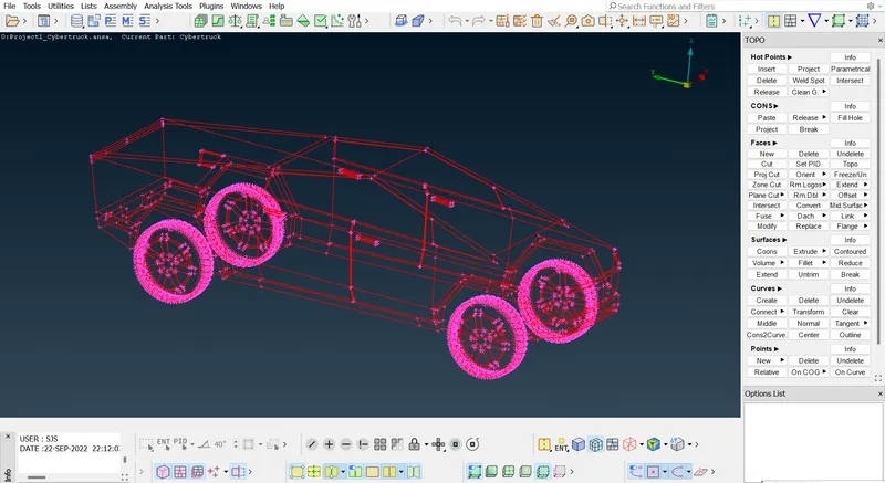
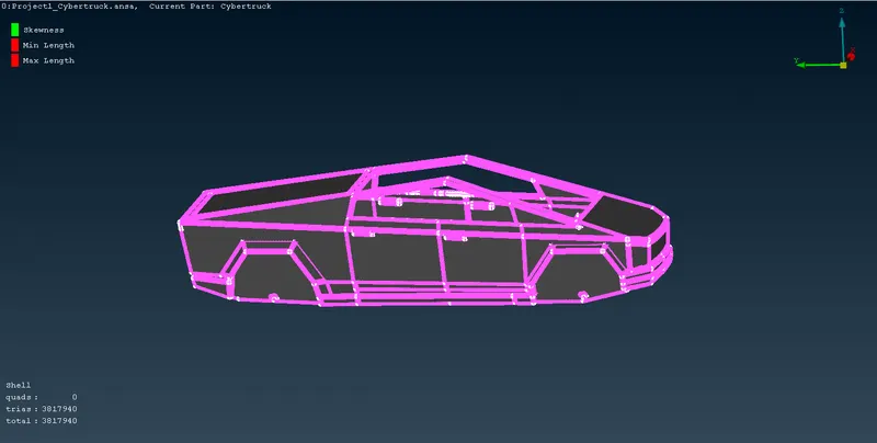
- Initial model of the cyber truck with the wireframe model.
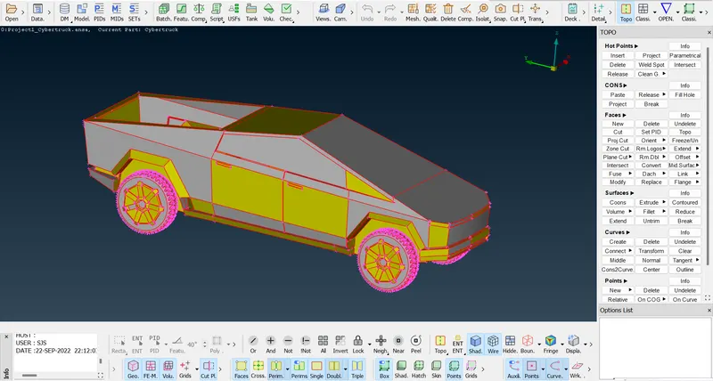
- Enable shadow mode and labels to show the tool name under the tools.
GEOMETRY CLEANUP:
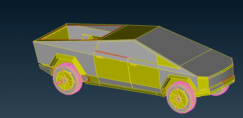
- Click TOPO->FACES->TOPO to clear some of the small errors automatically.
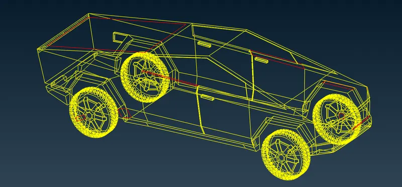
- Click ctrl+shift to see the model in the wireframe mode shortly.
- From this we can easily find the red coons.
- To close these red coons we can use either the FILL HOLE option or the FACES->NEW option.
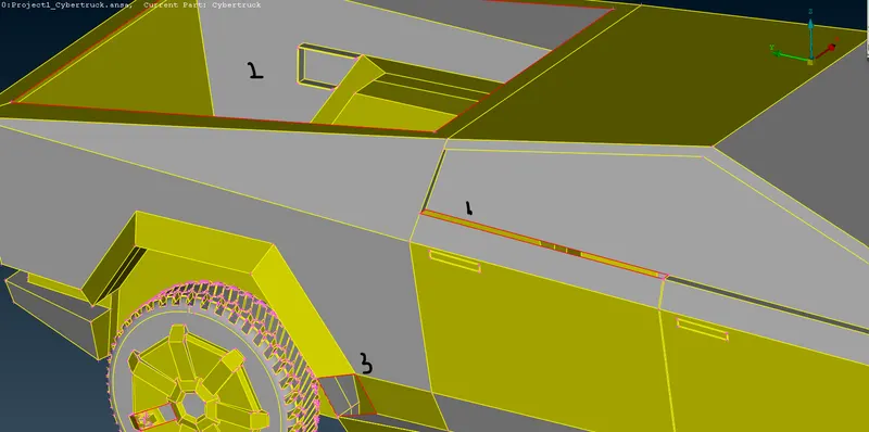
- All the red coons have been cleared.
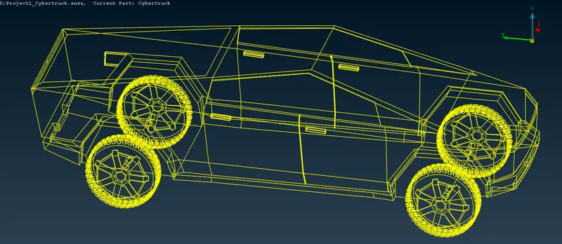
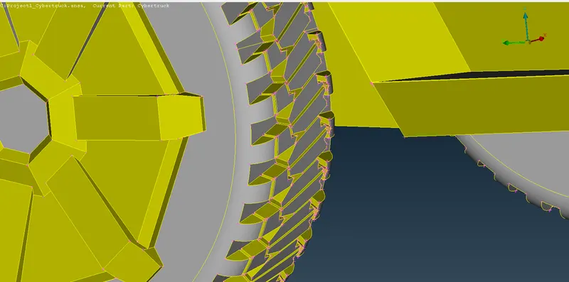
- Go for resolution change and make the shape perfect.
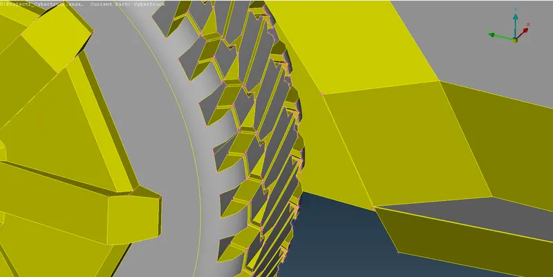
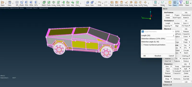
- Resolution has changed.
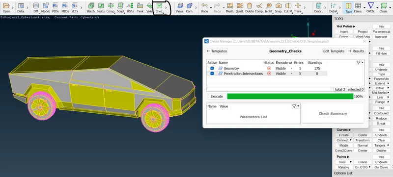
- Go for a geometry check and see the intersection and geometry errors.
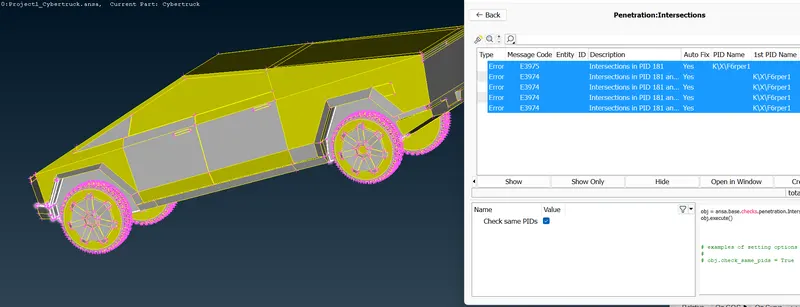
- Here it is showing 5 intersections errors and 1 geometry error,
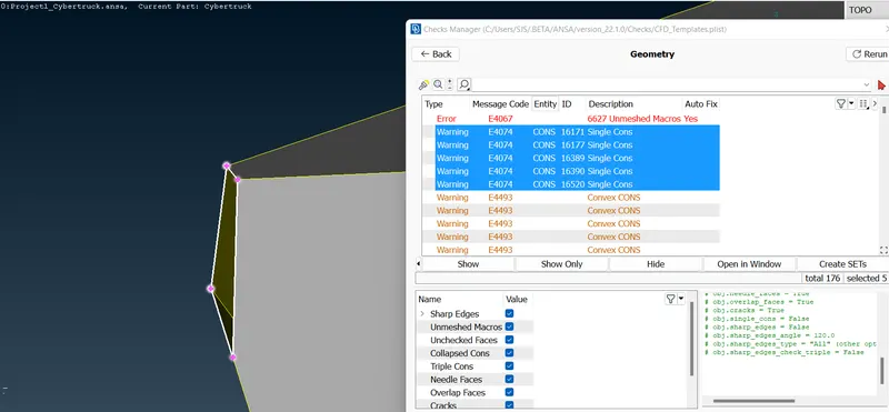
- We can neglect this single geometry error because still we haven't started the mesh part.
- Remaining all red coon warnings are showing this same unclosed part, so we can close it directly.
- We are only going to focus on the outer surface so we can directly delete the inner surfaces.
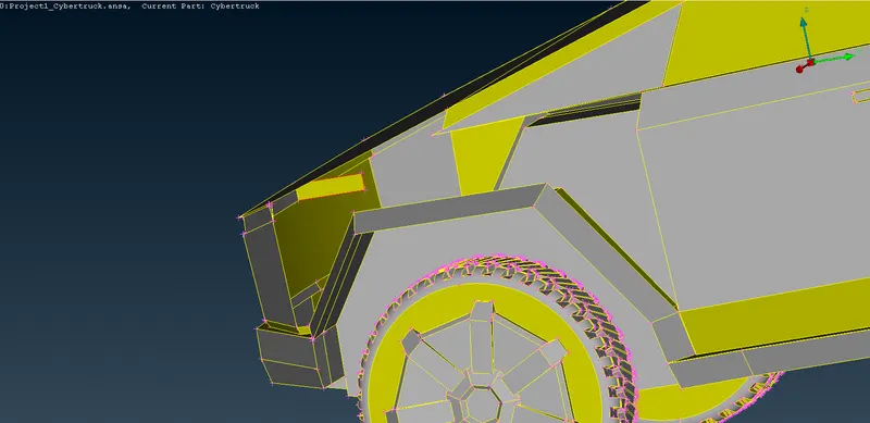
- After deleting the inner surface it is making red coon.
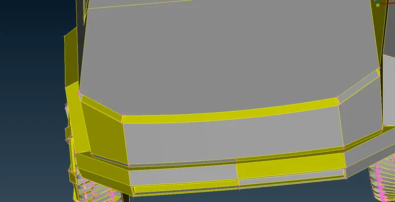
- Here we can use the fill hole, New options to create the new surface or either we can delete the upper surfaces to make it a single surface.
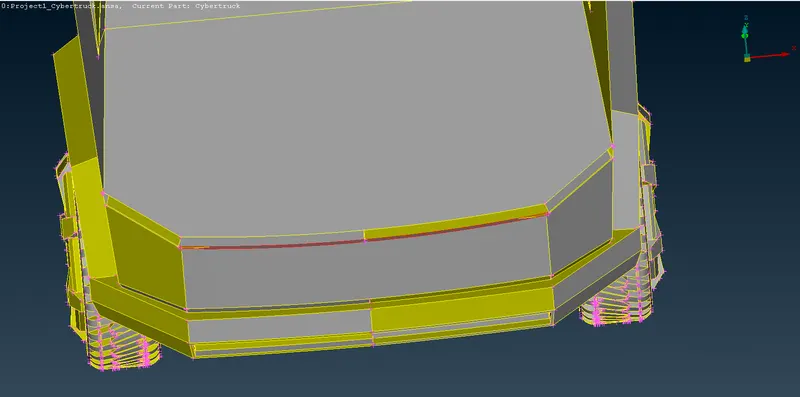
- New surface has been created.
- These are the intersection errors shown in the geometry check.
- Give first preference to the intersection errors and clear them.
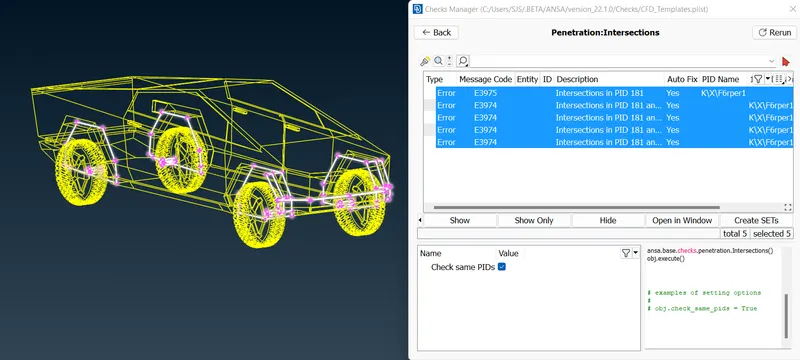
- To clear all the errors, Either we can work on the full model or we can cut the half section and work on the symmetry model.
- The same intersection error is showing on the other side also.
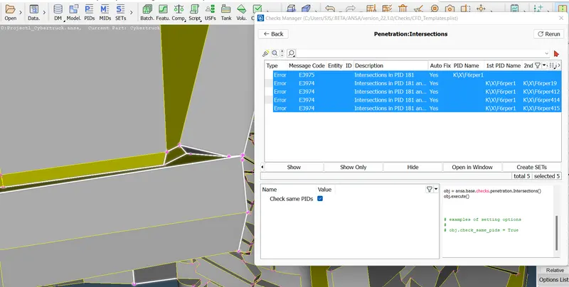
- After hiding the above surface, we can clearly see how the intersection is happening.
- Here we have to delete the unnecessary surfaces and create the new surface without any intersection.
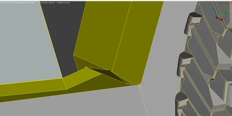
- The surface has been recreated.
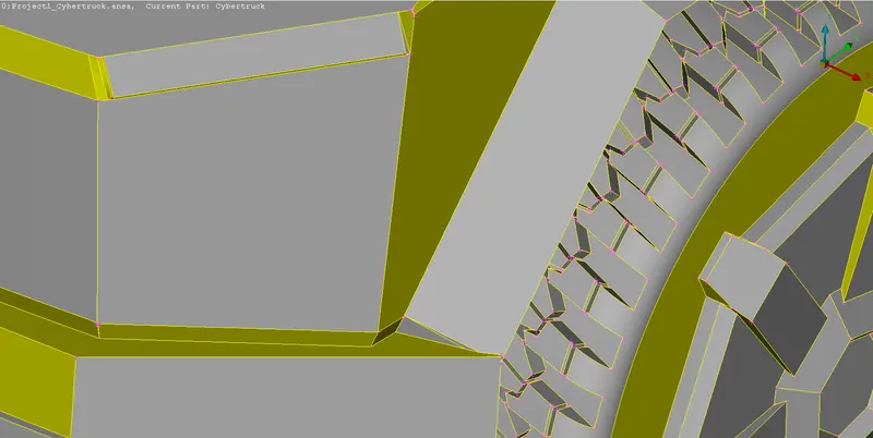
- Now go for a geometry check.
- Ther is no intersection error is shown in the recreated part.
- So do the same procedure for another side.
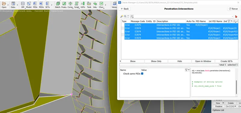
- Now there is no intersection errors are shown in the recreated section.
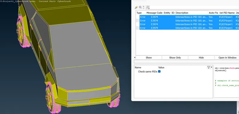
- Remaining are showing inside the truck.
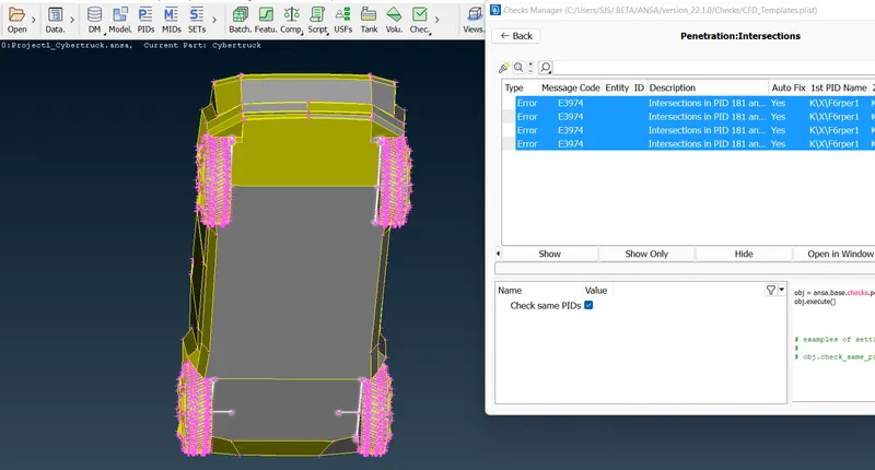
- Check inside and clear the intersection.
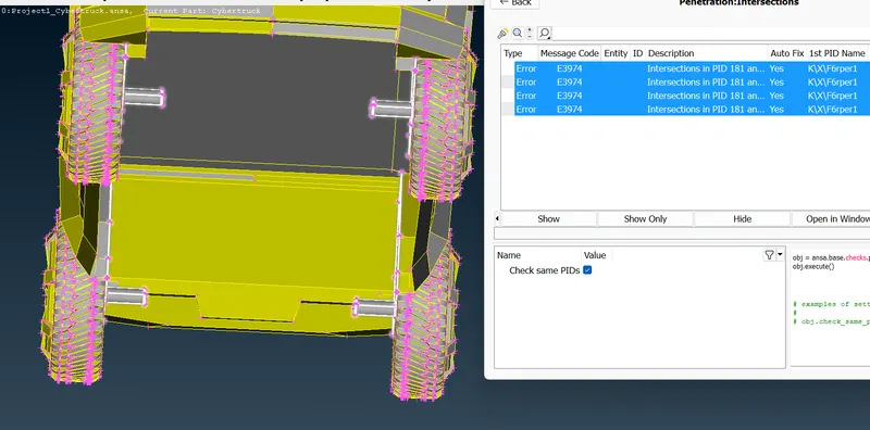
- All the 4 shafts are intersecting the surface.
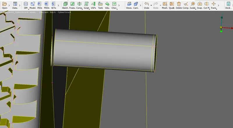
- After hiding the surface we can see the difference clearly.
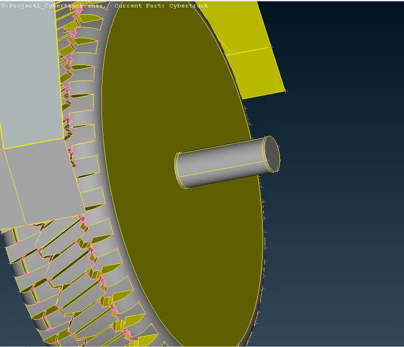
- Delete the extra surface and close the surface using the fill hole option.
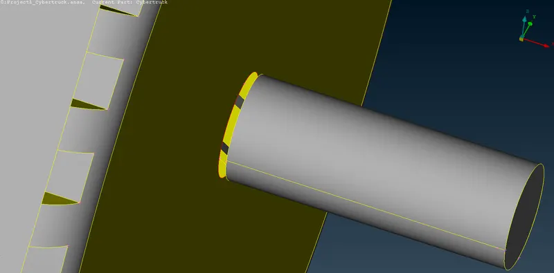
- Now it's done for this shaft. Do the same procedure for other also.
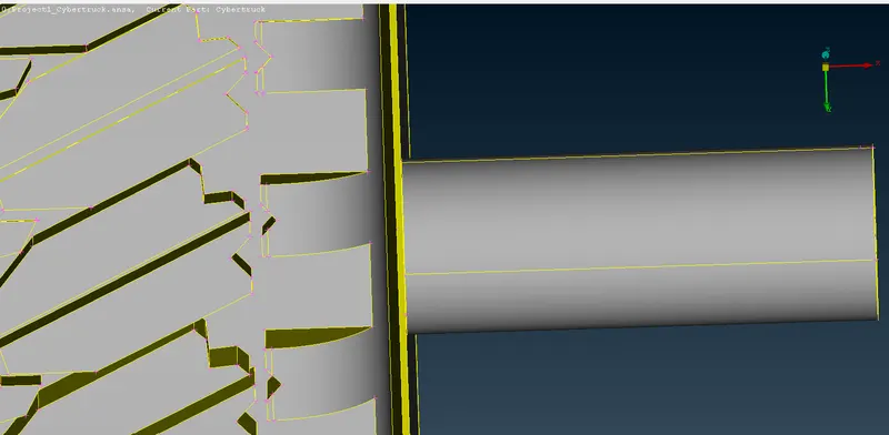
- After cleared all the intersection errors to do a geometry check,
- Now it's showing 0 intersection.
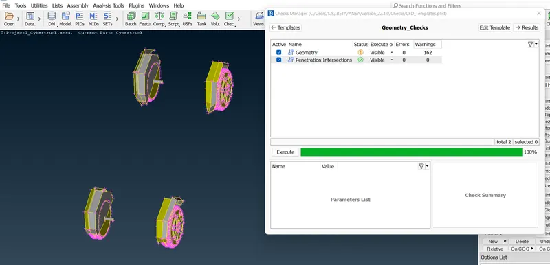
- Full body geometry check.
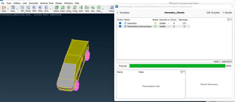
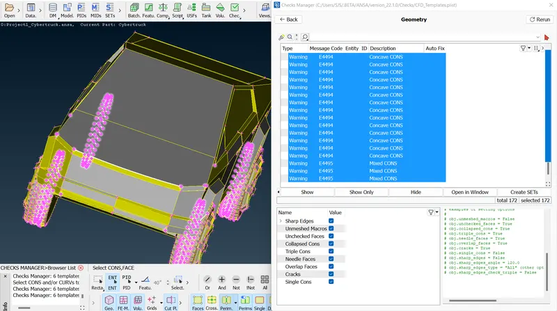
- All the warnings are showing because of the shape.
ASSIGNING PIDs:
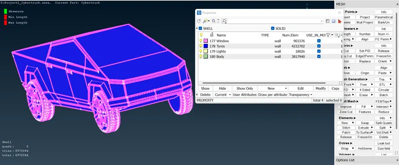
- PID->NEW->SHELL PROPERTY->CRAETE NAME->OK.
- PIDs has been created, Do right click->apply->select the surface->ok.
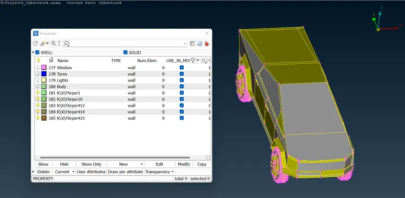
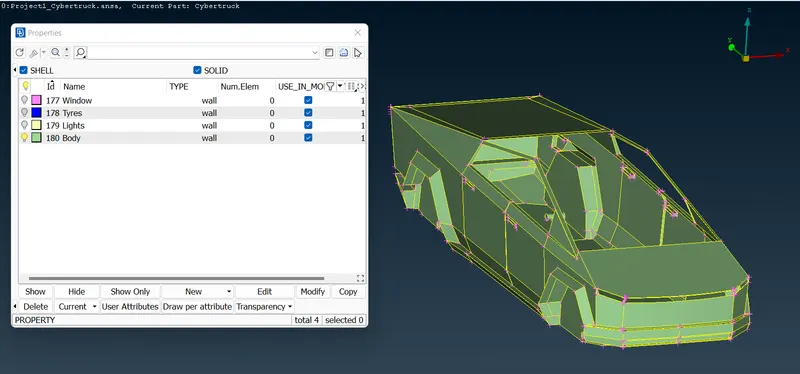
- PIDs has been assigned.
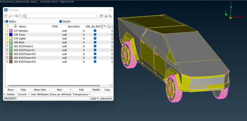
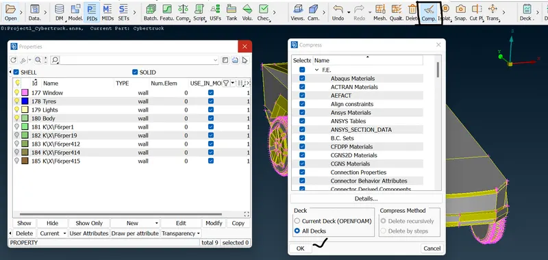
- Clear unassigned PIDs using the compress tool.
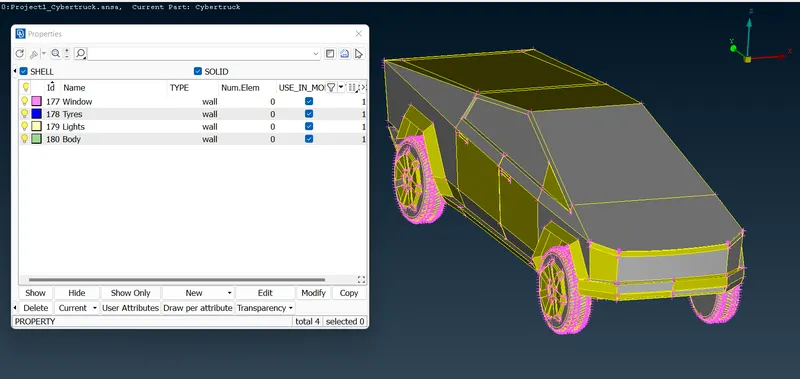
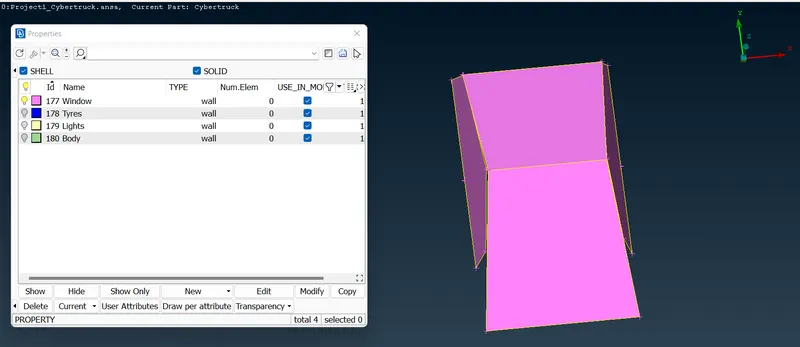
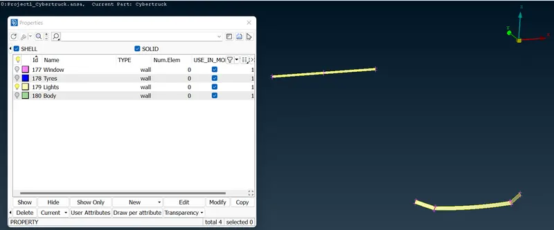
WINDOW'S:
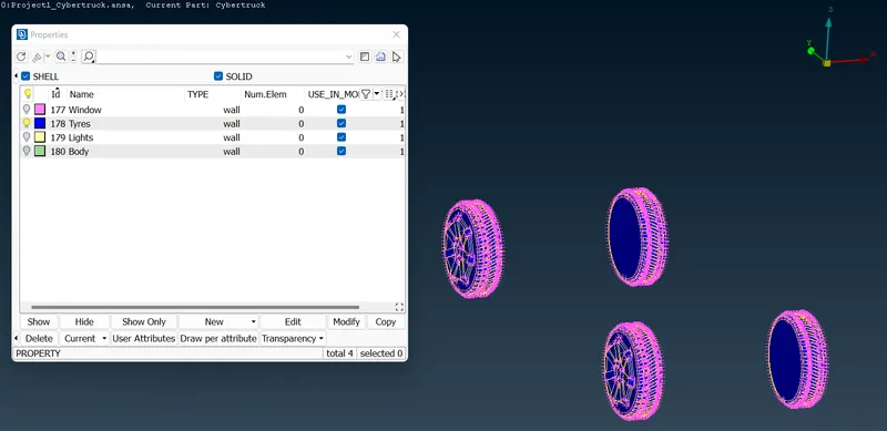
TYRES:
LIGHT'S:
BODY:
MESHING PART:
- For meshing we can follow the same target length as given in the BMW challenge.
- TYRE & WINDOW = 2mm
- LIGHT = 4mm
- BODY = 3mm
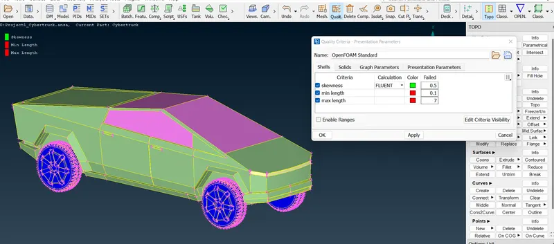
QUALITY CRITERIA:
- The quality criteria is fixed for the whole CYBER-TRUCK.
TYRE & WINDOW:
- Mesh Parameter:
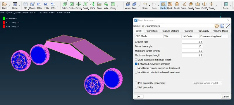
- Classic mesh->spacing->auto CFD->give perimeter & macros->mesh generation->CFD->visible.
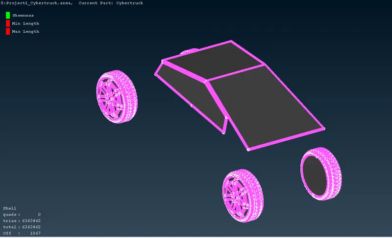
- Still there are 1067 off elements present. Do RECONSTRUCT/RESHAPE to improve the off elements.
- After many improvement also it is showing 4 off elements.
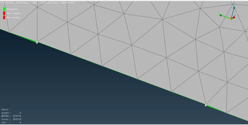
- Delete the part and recreate it in the other 3 sides in the 2 windows.
- After done with the changes we have always go for a FREE MESH->VISIBLE.
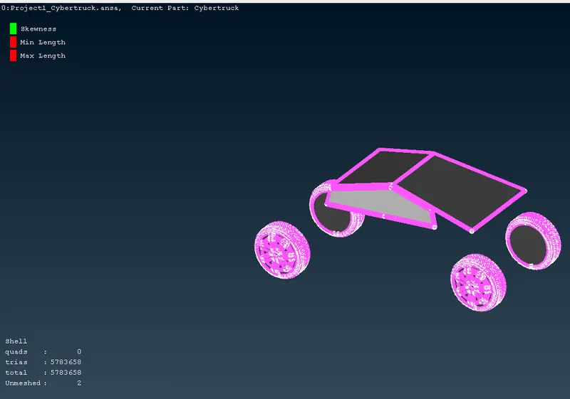
- Final mesh output with no off elements.
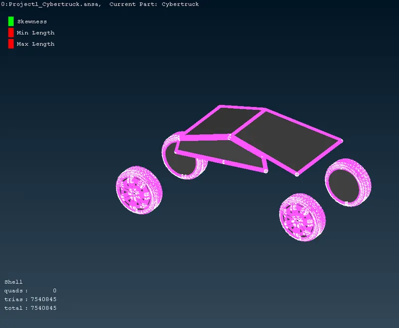
LIGHTS:
- Do the same procedure as followed above,

- Mesh parameter:
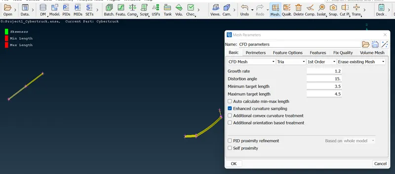
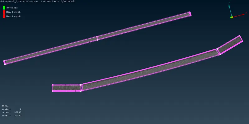
- Meshed with no off elements.
BODY:
- Mesh parameter:
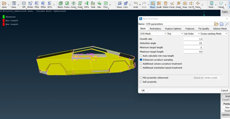
- 3553 off elements are showing, try to improve with reconstruct and reshape.
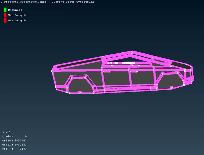
- After done with many improvement off elements are reconstructed.
TESLA OUTPUT:
CREATING TUNNEL:
- We are going to follow the same procedure as we did in the BMW tunnel,
- Full length we can take it as 5910 and side length as 2040.
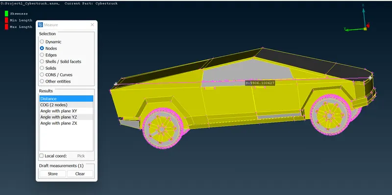
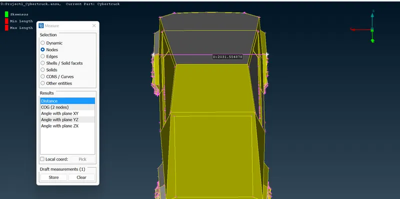
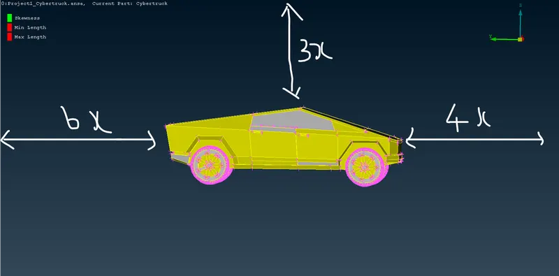
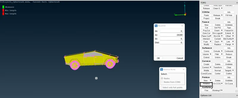
- To create relative point in the bottom surface, first create a hot point and take it as a dependent.
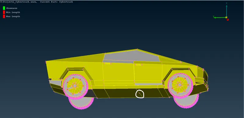
- Go to TOPO->POINTS->RELATIVE->and select the mid-hot point.
- For the bottom point I have taken 1500.
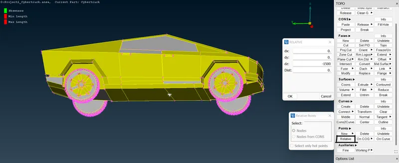
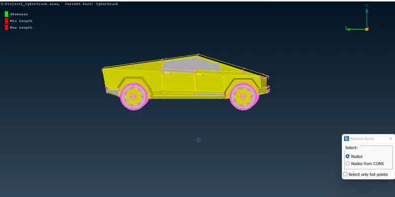
- Create the front tunnel,
- [Mid hot point+4x] 2540+23640=26180.
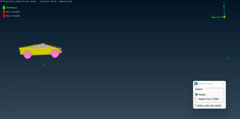
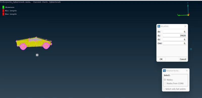
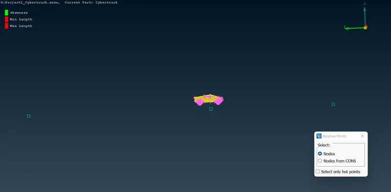
- To create back tunnel give the length as 39,020mm.
- [Mid hot point+6x]
- Now sides we have to take X-full length,
- X=5910mm.
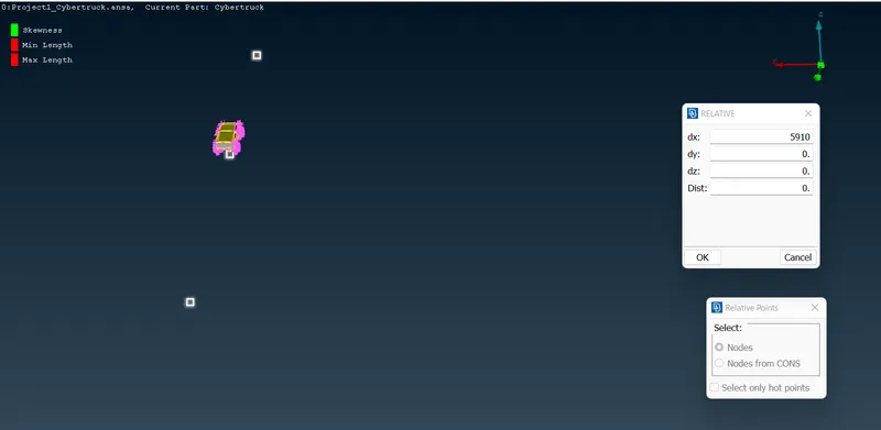
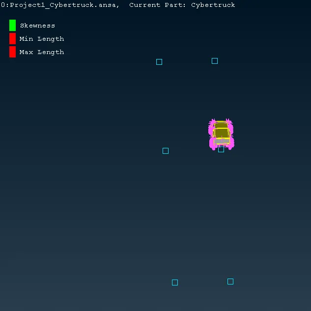
- Do the same with the negative value.
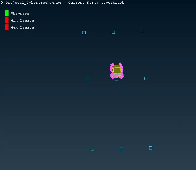
- Create only a single relative point in the upper,
- 3x+1500+2040=21270mm.
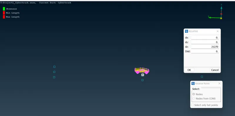
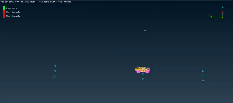
- Now create a COONS to connect the points.
- TOPO->CURVES->CREATE->SELECT THE POINTS->MIDDLE CLICK.
- Finally create a new surface and delete the created coons.
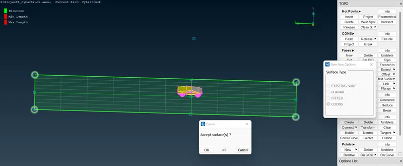
- Automatically it will ask for the PID, Create it newly.
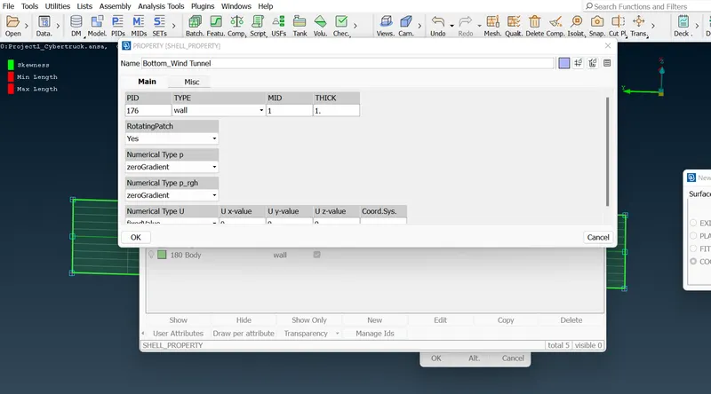
- Surface has been created with PID.
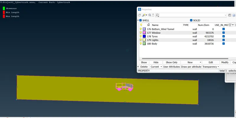
- To copy the same bottom surface for the upper point go to TOPO->FACES->OFFSET->FACES.
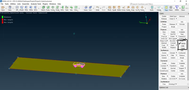
- Click on the surface and middle click.
- It will ask the upper value to create a surface.
- Give negative value as the direction arrow shows the other direction.
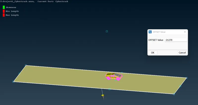
- The surface has been created successfully.
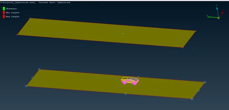
- Now create the other sides and assign PIDs.
- Full Tunnel view with assigned PIDs.
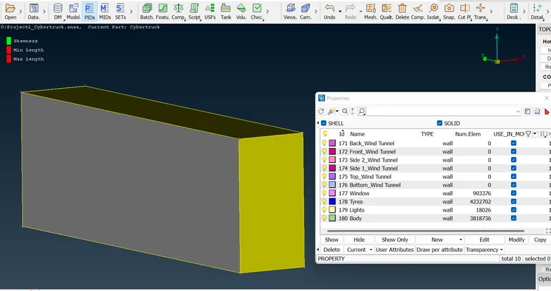
WIND TUNNEL MESH:
- In the mesh parameter also we can follow the same procedure as followed in the BMW challenge.
BOTTOM TUNNEL:
- For the bottom tunnel, the minimum length is 45 and the maximum is 55.
- Mesh Parameter:
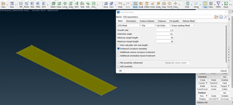
- Go to classic mesh->perimeter->spacing->auto CFD->mesh generation->CFD->visible.
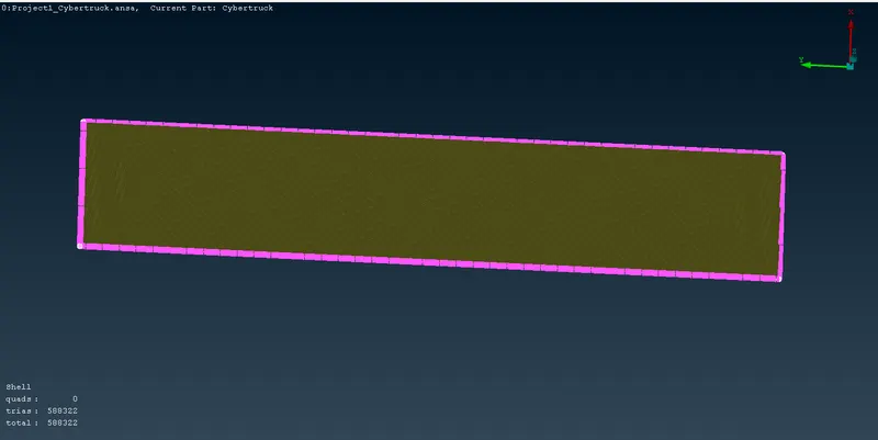
- Meshing is completed for the bottom surface tunnel.
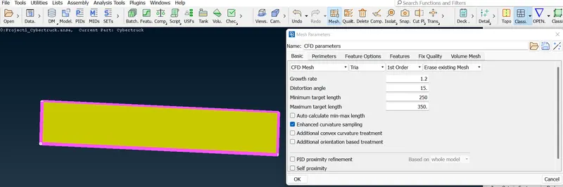
- Do the same for upper surface tunnel. But change the length minimum as 250mm and maximum as 350mm.
TOP TUNNEL:
- Here we are changing the length depending upon the side wind tunnels.
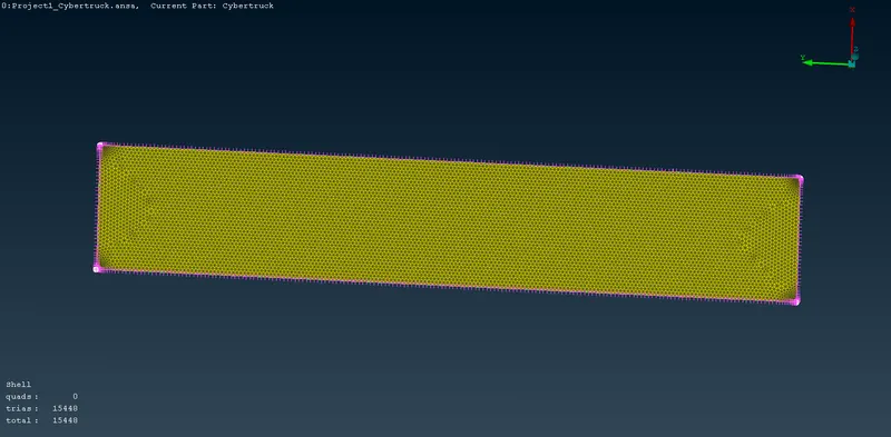
- Mesh done for the upper tunnel surface also.
4 SIDE TUNNELS:
- For the sides we are going to use MANUAL CFD to gradually increase the range from the lower to the higher.
- The range we are going to define is from 20 to 100. Before giving an ok we have to select the direction from which should start.
- For that only we have used the smaller range to the bottom surface and higher range to the upper surface.
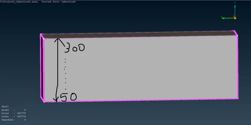
- Manual CFD limits:

- Select the direction from the lower to the higher range.
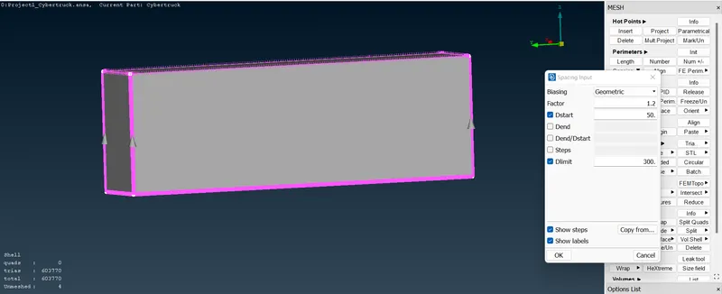
- Reference view:
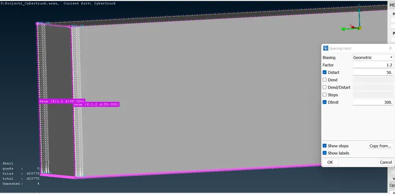
- Go to spot mesh and visible.
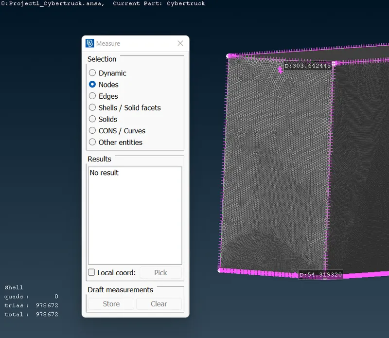
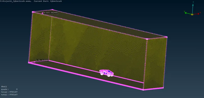
- Final mesh view for WIND TUNNEL.
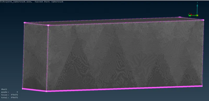
- Used the measure tool to show the gradual limit.
FINAL OUTPUT:
https://drive.google.com/file/d/1rlhEyP8vSlhdso7kQMuoYhbX4aJYXKEH/view?usp=sharing
 https://drive.google.com/file/d/1rlhEyP8vSlhdso7kQMuoYhbX4aJYXKEH/view?usp=sharing