Week 2 Challenge : Surface meshing on a Pressure valve
AIM:
- The surface meshing on a pressure valve by solving the geometrical errors and topology cleanup accordingly with a different target length and element type.
Procedure:
- Open ANSA software and enable labels to show the tool's name.
- Import geometry from file->open->file location->challenge2.ansa
- After importing the geometry change ENT mode to PID mode for better usage.
- Enable shadow option for the visibility of the geometry surface.
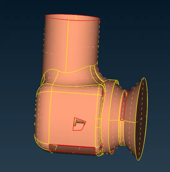
- By disabling the shadow option, double cons, triple cons, and cross hatches we can find the single cons easily.
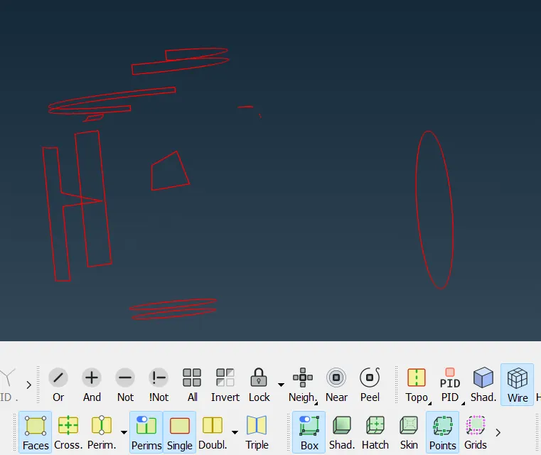
- By clicking the ctrl+shift option, The geometry will show like this.
- The unfinished surface's/red con (holes) will be created newly or by the fill hole option.
- Always check before creating the surface by middle click and make sure which option is perfect for the cons.
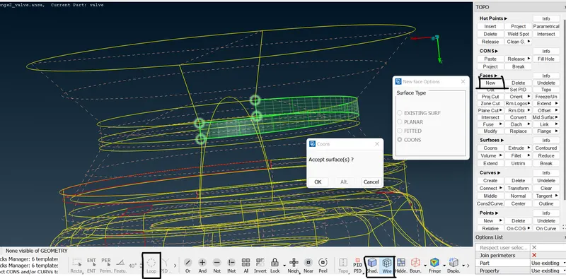
- Here the surface is created newly with the following sequence TOPO->FACES->NEW->COONS->LOOP->SELECT THE SURFACE and give OK.
- After creating the surface.
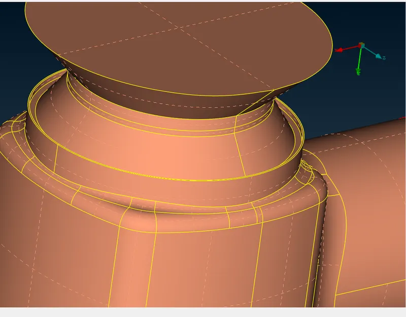
- The same sequence has been followed here to create the surface.
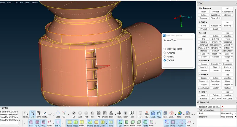
- Checking the surface model before creating.
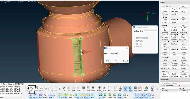
- Used Fill Hole option, Because if we use a new surface here that will make unwanted cross hatches.
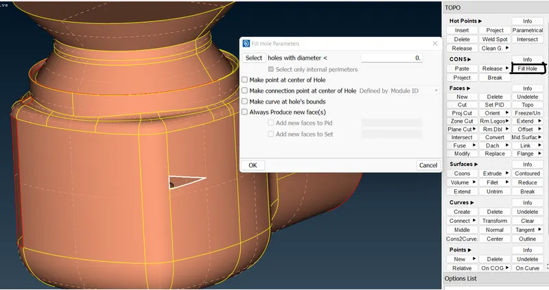
- Both Fill Hole and New options will be suitable to create the surface here.
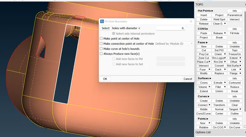
- This is the best example and difference between the New and Fill Hole option.
- In the small red con creating a new surface is a good option but if we see the below red con creating the new surface is not a good option. So instead, here we can use the Fill hole option.
- For all the red cons or creation of the surface is followed by the above sequence.
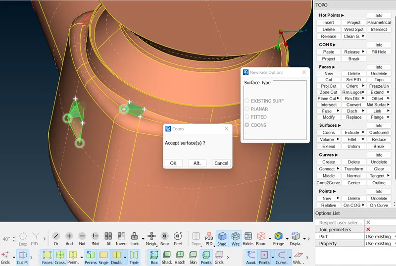
- Fill Hole option is used for this red con.
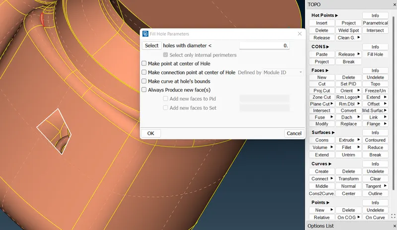
- With a surface view.
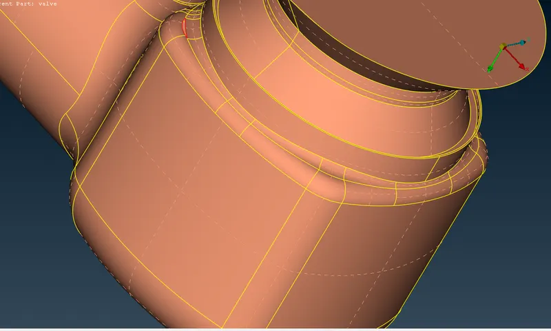
- Here, I have deleted the above surface 1 and merged both the 1 and 2 holes by fill hole option for the better creation of the surface.
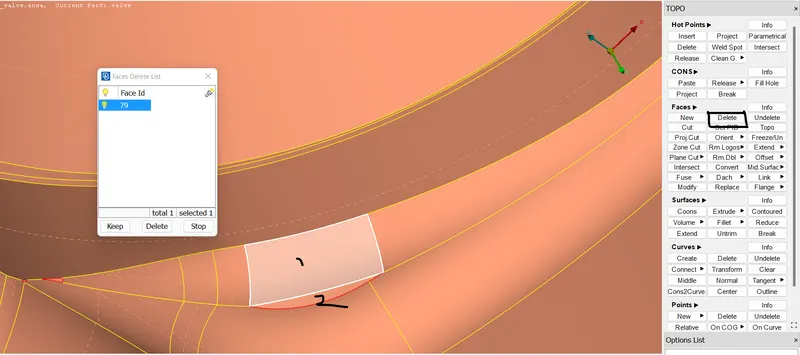
- After creating the surface.
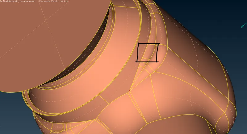
- TOPO->FACES->NEW->COONS->SELECT THE SURFACE->GIVE OK.
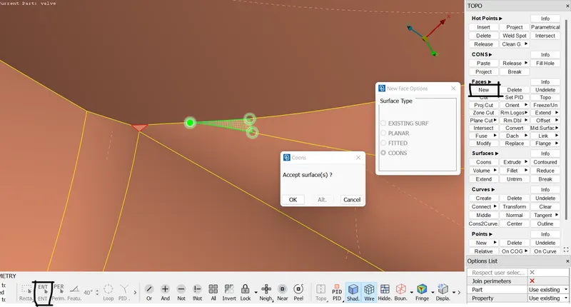
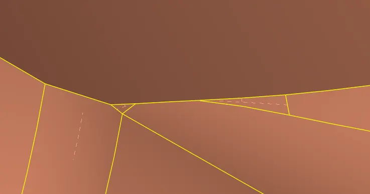
- To close the open surface, we can use both options. Here Fill Hole option is used.
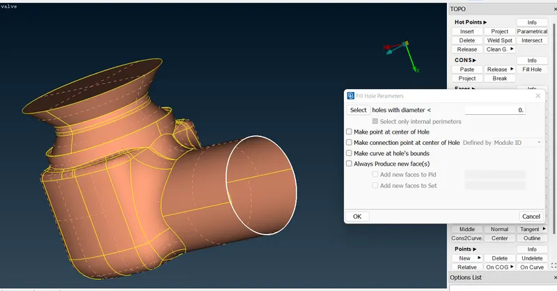
- Closed view.
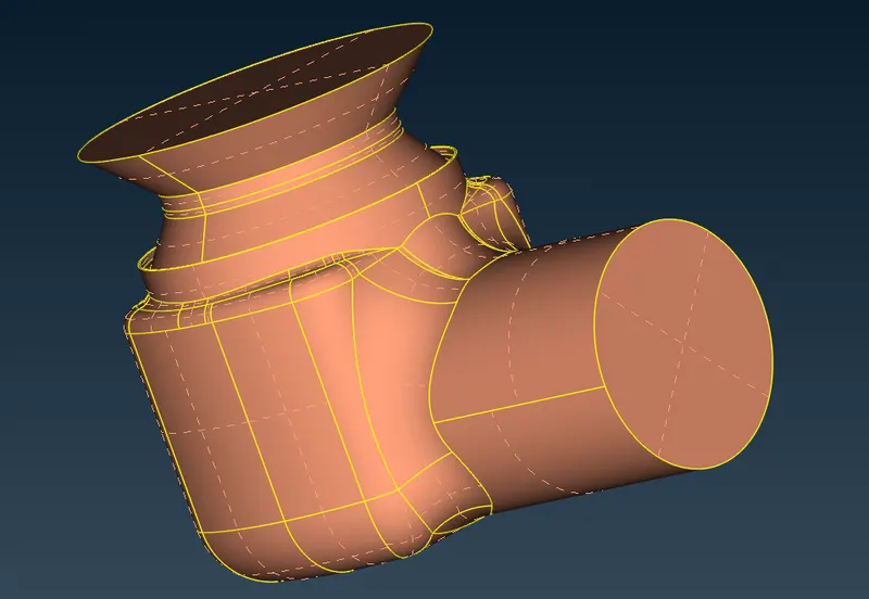
- For these complex red cons we should always create a surface by 2 times.
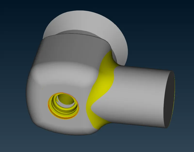
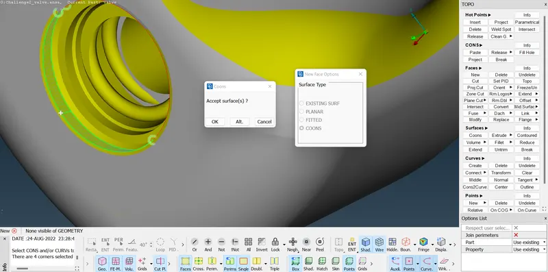
- Selected half circle in the upper and lower surfaces and used the New option to create the surface.
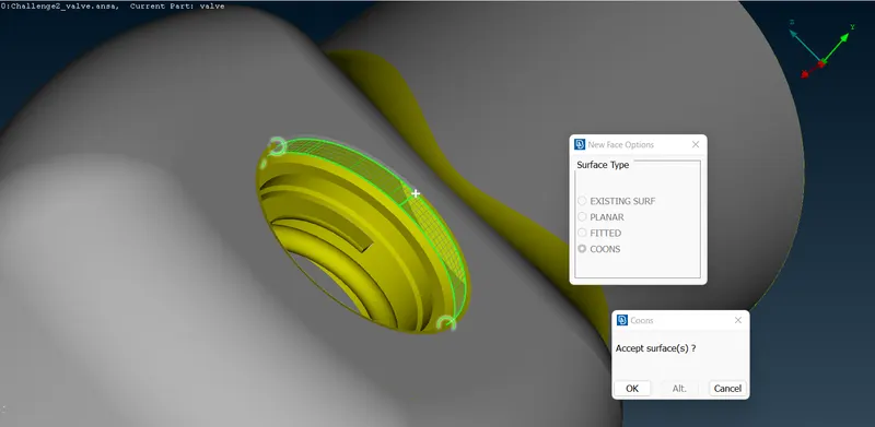
- Remaining half is done through the same method or we can also use the Fill Hole option.
- Final View.
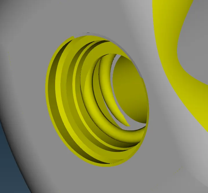
- After clearing all the red cons, We have to find the other errors by using the Check Manager tool.
- Inside the valve some intersection errors are shown.
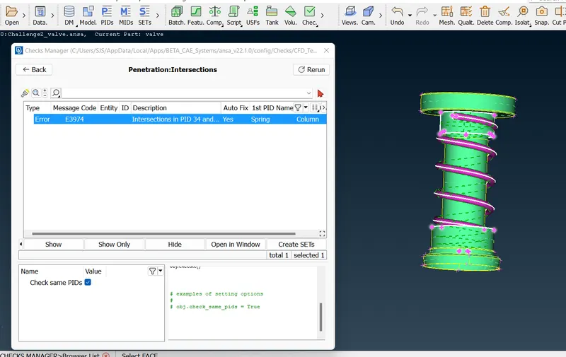
- So, delete the other surfaces of the valve and lock the remaining to do they intersect.
- Go to the PIDs tool and create the surface names(Also, we can change the color by editing).
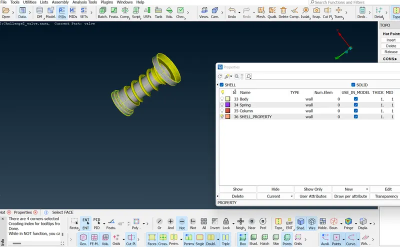
- To apply the name for their respective region select the Not option and the PID Region.
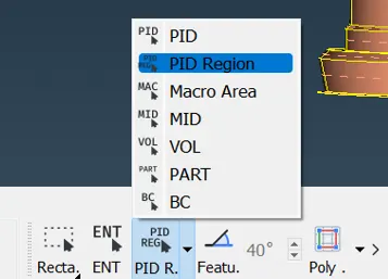
- Select the spring and middle click to hide.
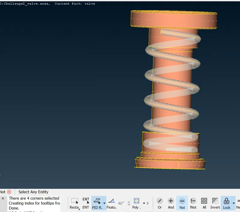
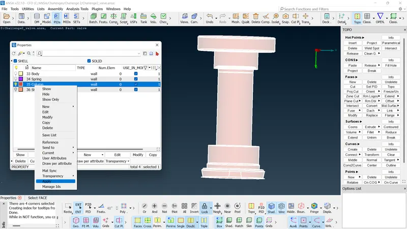
- Select column and apply.
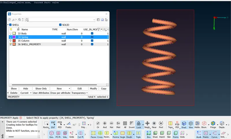
- The same way is followed for the spring.
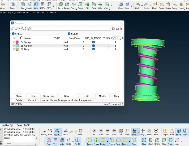
- Now naming is done. After this, If we choose by the name it will hide the other parts.
- Go to TOPO->FACES->INTERSECT->and select the 1st surface as COLUMN and the 2nd surface as SPRING->MIDDLE CLICK.
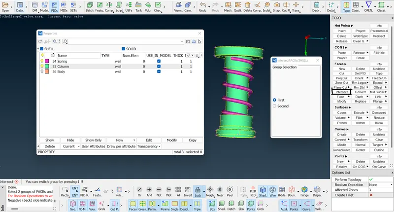
- Delete the unwanted or extra surfaces and keep the other surfaces.
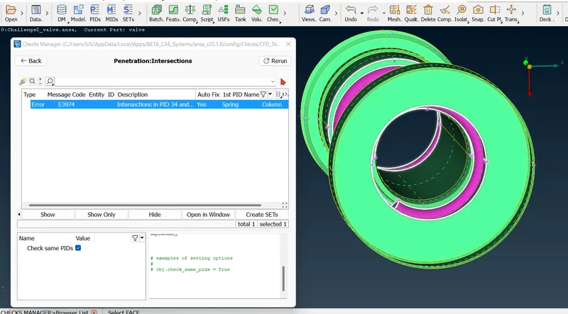
- After that go to check manager and execute.
- Finally intersection errors are removed.
- Now check the warnings and if it is removable go forward.
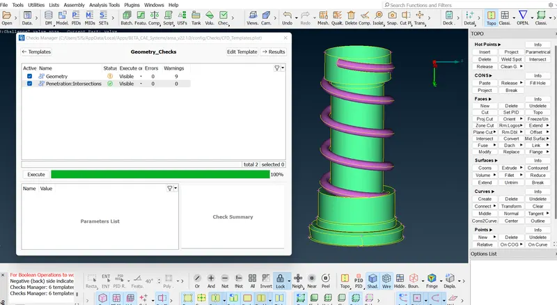
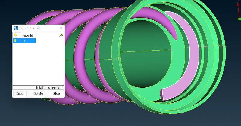
- Delete the extra unwanted surface.
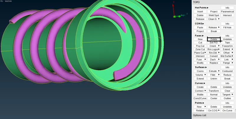
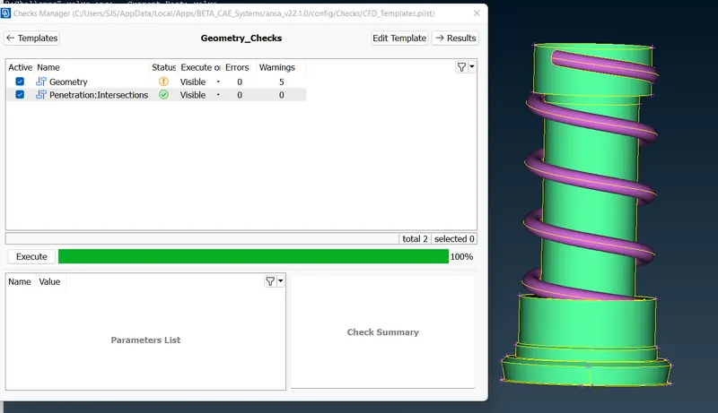
- Now the warning section shows only 5.
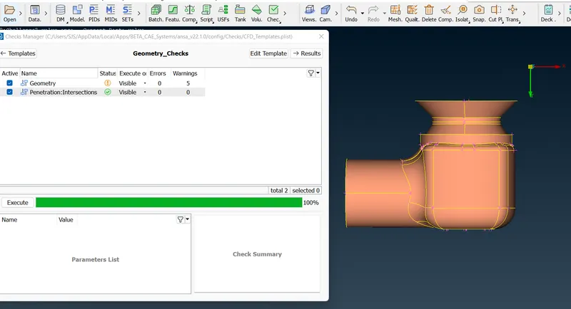
- Click the ALL tool and check the errors globally.
- The errors are 0.
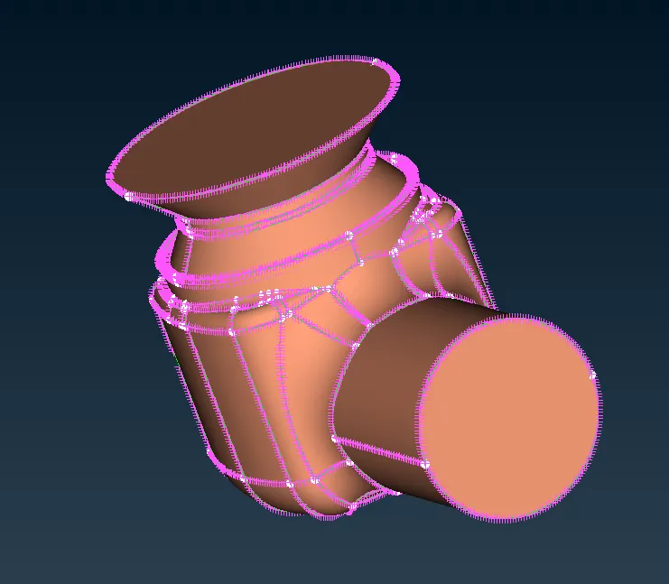
- Make sure, before meshing all the in and out flows should be closed.
- Here we have to close the hole by surface.
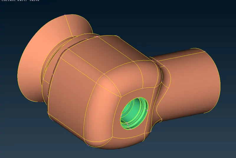
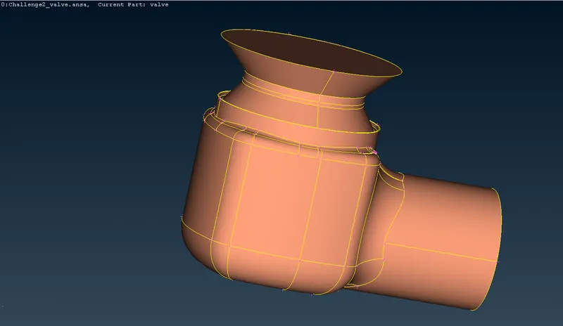
- Final model.
- Start the meshing part. Go to CLASSIC->MESH.
- Give target lenth one by one and element type as 'TRIA' and mesh the model.
TARGET 1 :
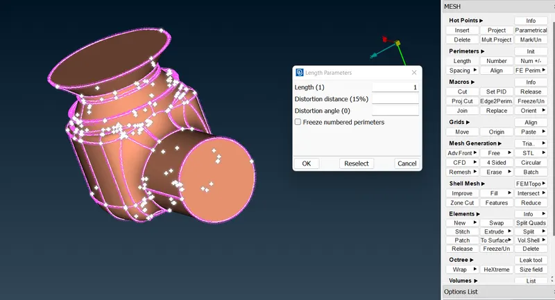
- Go to MESH->PERIMETERS->LENGTH.
- Give 1st target length=1 for both perimeters and macros.
- Select the mesh tool and set TRIA as an element type.
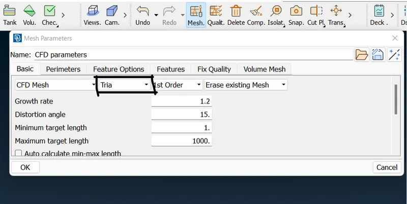
- In mesh generation click CFD Mesh->Visible.
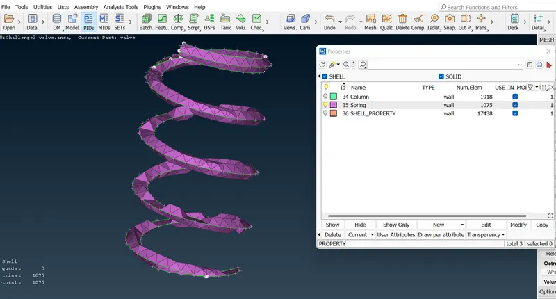
- Output of 1mm target length meshing.
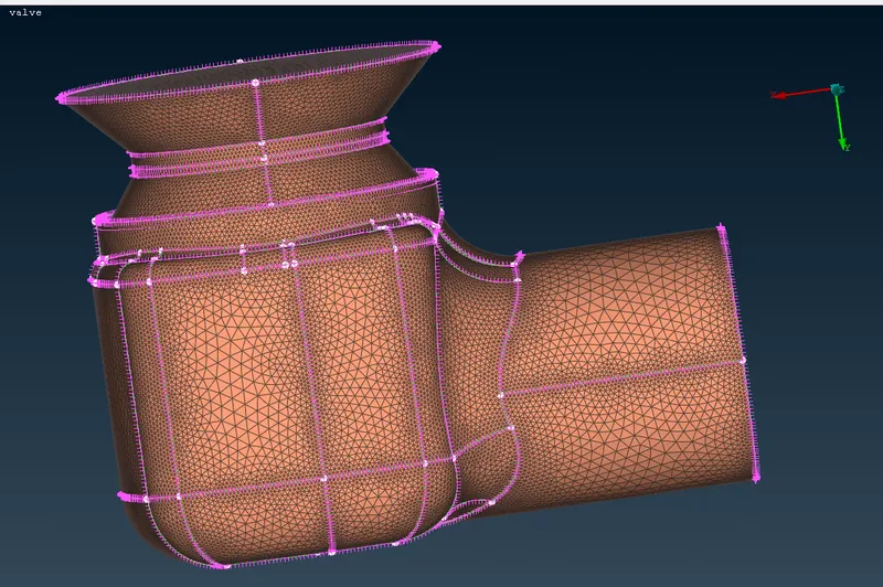
- While checking the mesh for the spring alone it is very fine clear and curvy.
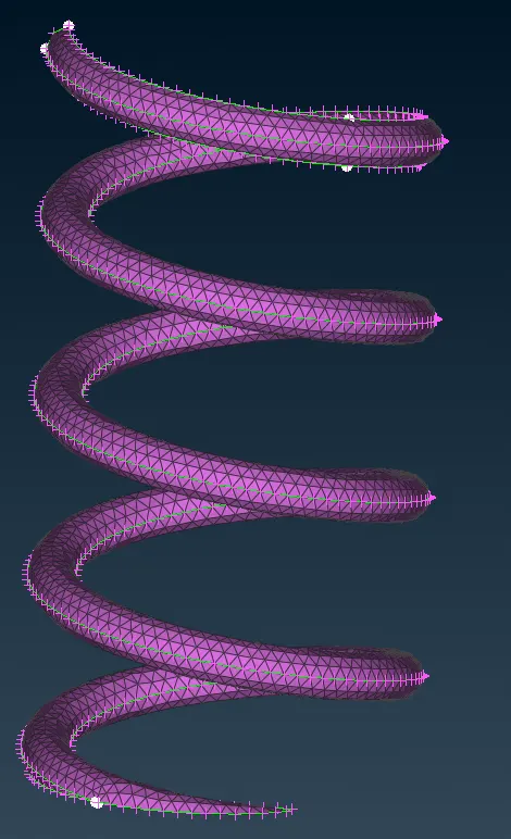
TARGET 2:
- Give 2nd target length=3 for both perimeters and macros.
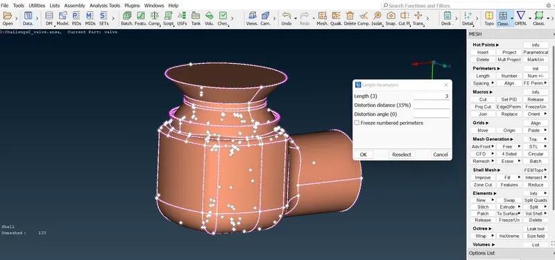
- Target length 3mm mesh model.
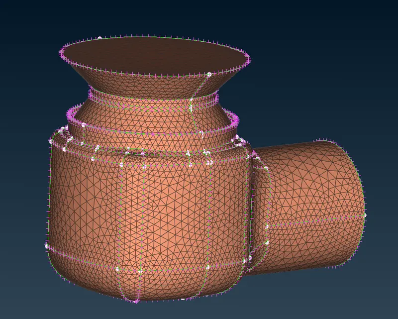
- Here the mesh in the spring is not that fine and curvy compared with 1mm mesh.
TARGET 3:
- Always erase the previous mesh model.
- Set final target length=5 and give ok.
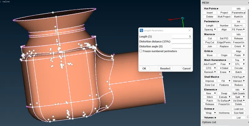
- Select CFD Mesh and click visible.
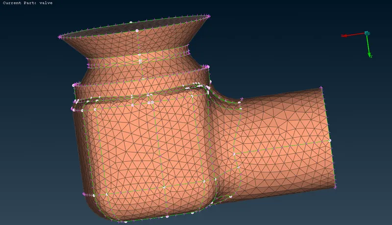
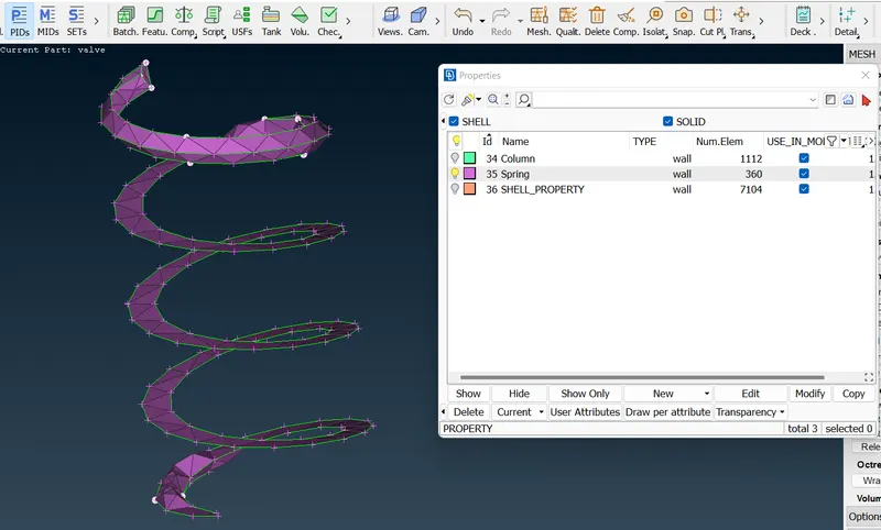
- In this 5mm mesh, the spring is completely not fine and curvy compared with 1mm and 3mm mesh.
RESULT:
- The best mesh in all the 3 cases is a target length of 1mm.
- The reason behind the answer is based on the spring mesh.
- If we closely see the triangles present in the 3 cases spring and the whole model, the target length of 1mm is giving the curviest spring.
- From this we can conclude the best result as a 1mm target length.