Week 4 Challenge : CFD Meshing for BMW car
Aim:
To check and solve all geometrical errors on half portion and Assign appropriate PIDs. Perform meshing with the given Target length and element Quality criteria.
After meshing the half model, Do symmetry to the other side.
Objective:
We have to follow the given parameters and then to create a eight type of mesh for the given geometry model.
Target lengths for the different parts of a model are as follow:
- Body - 3 mm
- Lights - 4 mm
- Grills - 1 mm
- Rims and Tyres - 2 mm
- Optical Rear-view mirror - 2 mm
- Window - 2 mm
- Silencer - 3 mm
- Logo - 1 mm
First step is we have to uploaded the given geometry model in ANSA.
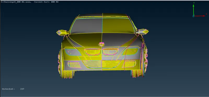
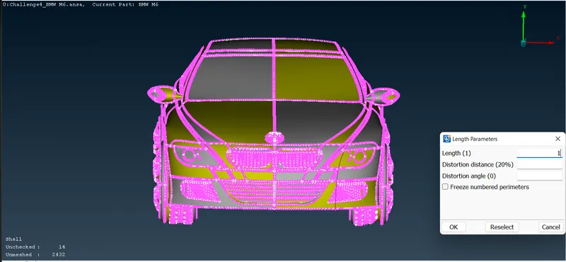
The given model is don’t have a perfect perimeters shape so we have to change that. First, we have to go mesh deck – perimeters – macros – middle click we will give 1mm.
Now the geometry model is getting perfect shape.
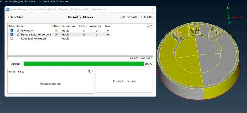
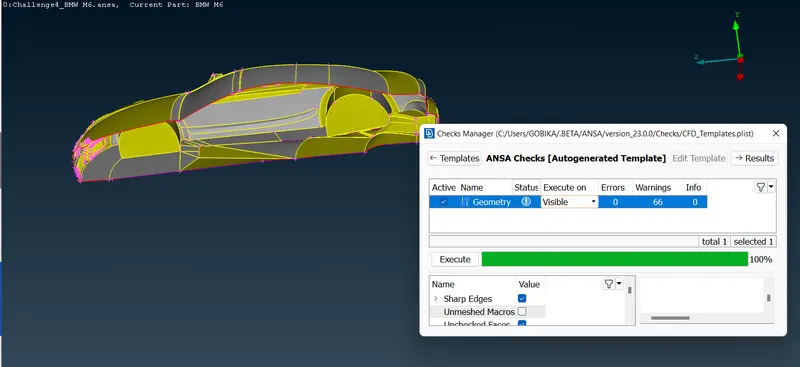
First we to open our model in ANSA, and then we will perform checks on the geometry to see all the errors that are present in the model. Beside script tool
there is arrow bottom, click on it and select checks and select geometry. Then from the bottom part of the window we will select the things which we want to check then click execute.
We can see many errors listed. Let’s resolve them.
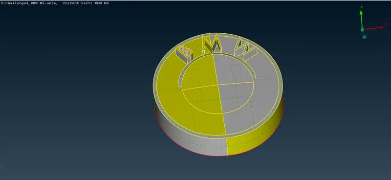
We have to Isolate each and every part of the car such as front Grills, Logo, Wheel and Rim, Lights, Window, Mirror, Silencer and body.
Then perform surface clean-up of each part by deleting overlapped, unwanted surfaces and penetrated surfaces by using universal delete option, fill the
gaps present by creating new surface from new option on the left tabular column followed by selecting either Existing Surf or COONS or FITTED option.
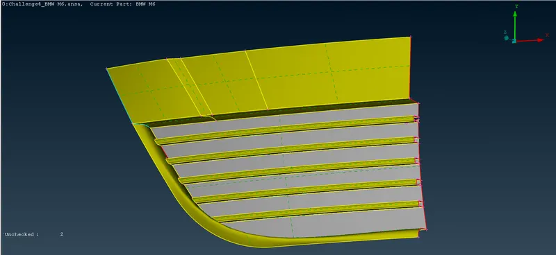
After clean-up check whether any triple cone or single cone exist if any single or double cones are there so necessary step to eliminate those
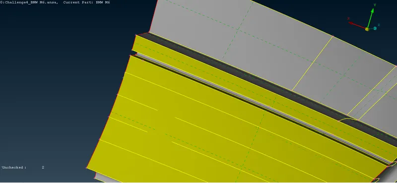
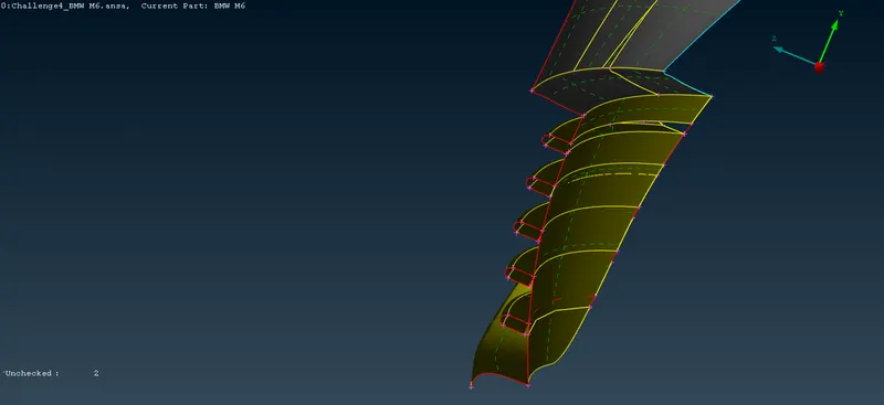
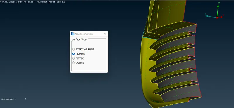
check whether any triple cone or single cone exist if any single or double cones are there so necessary step to eliminate those
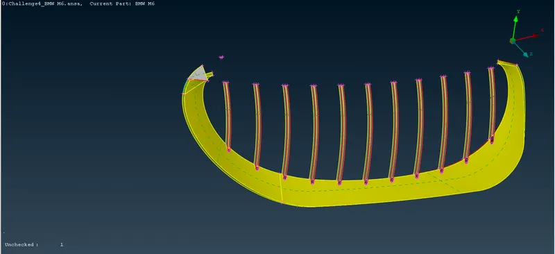
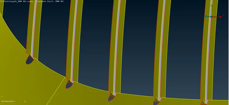
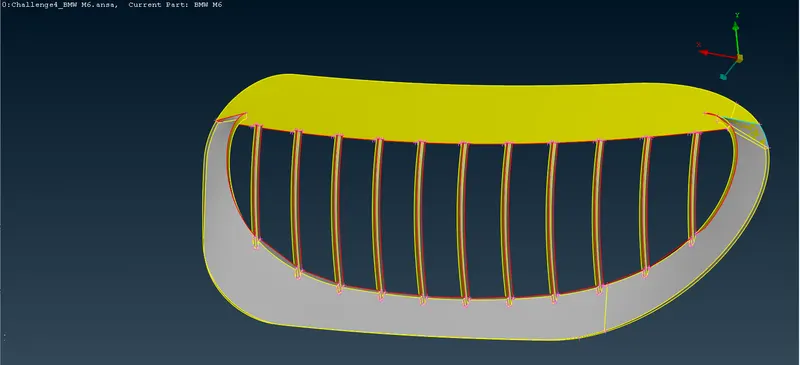
Then perform surface clean-up of each part by deleting overlapped, unwanted surfaces and penetrated surfaces by using universal delete option, fill the gaps present
by creating new surface from new option on the left tabular column followed by selecting either Existing Surf or COONS or FITTED option.
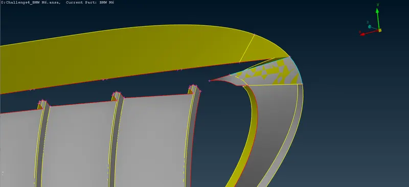
Remove small faces, unwanted hot points and delete unwanted cuts on the surface of each part
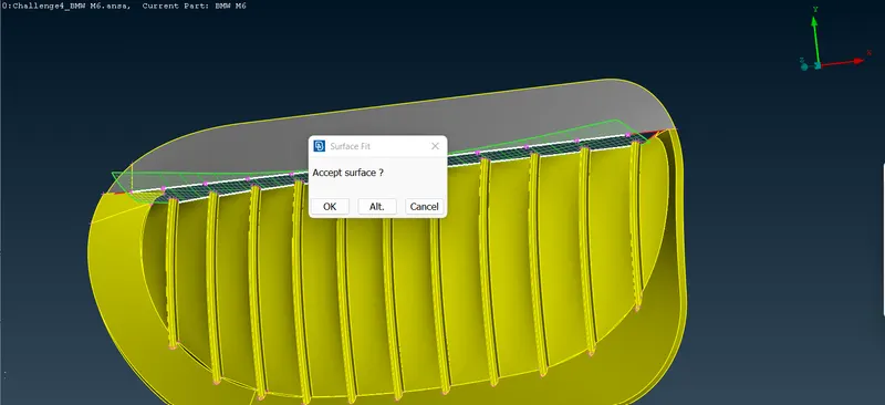
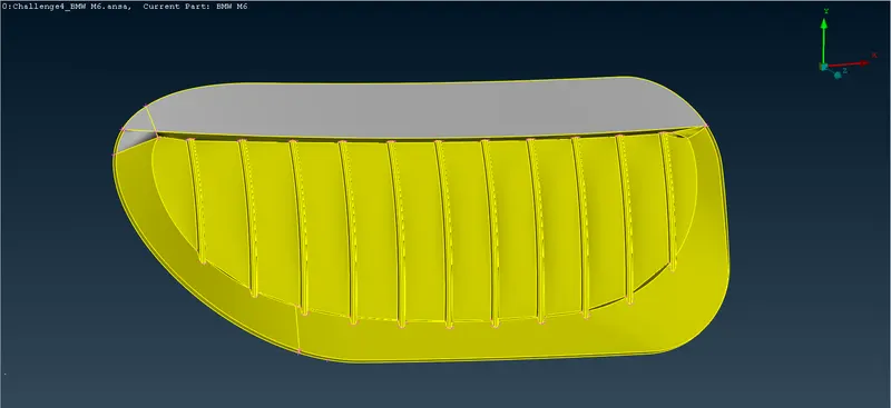
To perform surface clean-up of each part by deleting overlapped, unwanted surfaces and penetrated surfaces by using universal delete option.
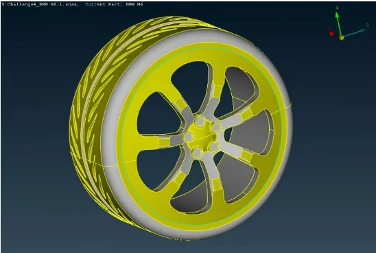
In this tyre part cleared the triple cons and extra surfaces
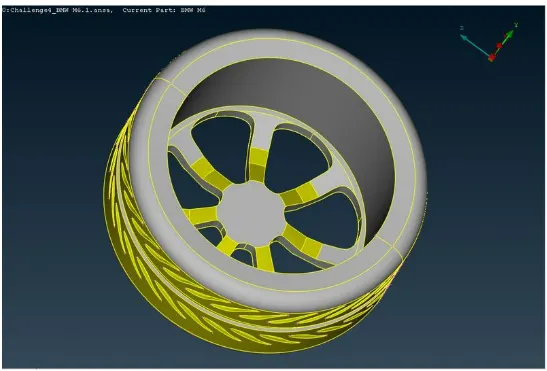
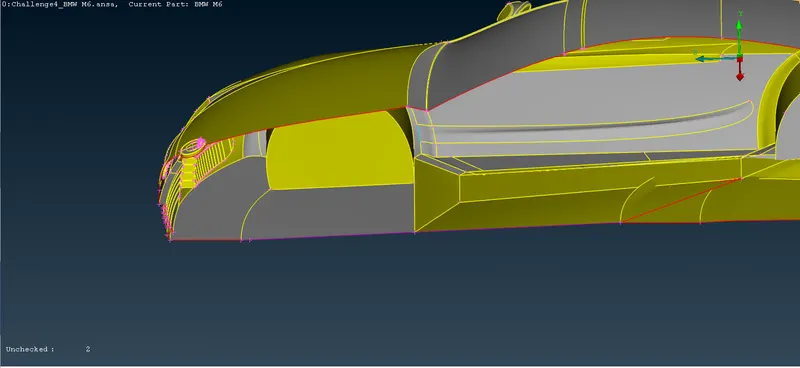
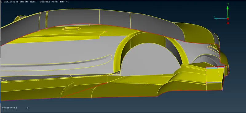
Remove small faces, unwanted hot points and delete unwanted cuts on the surface of each part
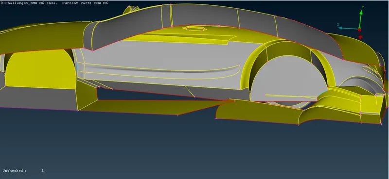
Use Cons2Curve or Create curve option to get the traces of deleted faces which help to create border line for deleting cons
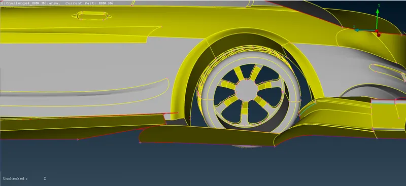
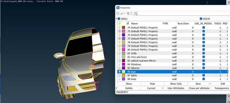
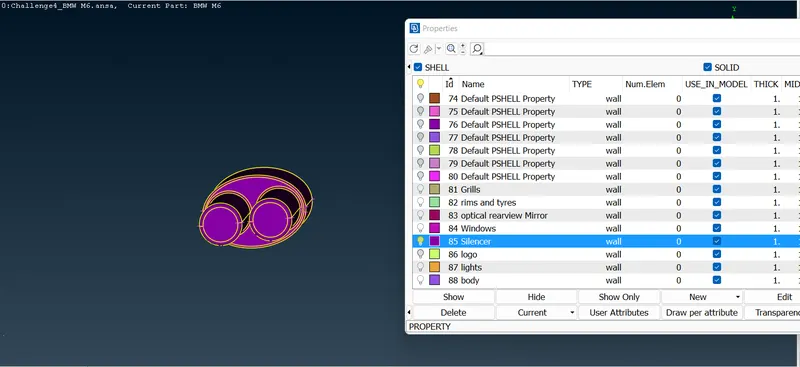
After completing the clean-ups provide each part with suitable PID name by selecting the Property from top tabular column and creating new PIDs and by renaming
existing PIDs. Then assign each PIDs appropriately. The figure shown below represents the completed geometry.
The empty PIDs with the default names were removed by Compress option
Target lengths for the different parts of a model are as follow:
- Body - 3 mm
- Lights - 4 mm
- Grills - 1 mm
- Rims and Tyres - 2 mm
- Optical Rear-view mirror - 2 mm
- Window - 2 mm
- Silencer - 3 mm
- Logo - 1 mm
After the topo clean-up next step is surface mesh it will be generated first under Classic Mesh Model. The PIDs were grouped by mesh size for convenience.
For each size: perimeters, macros, mesh parameters and quality criterion were defined as follows.
Go to Perimeters - Length - Perimeters, the whole geometry can be selected with the box select tool. After selection, the middle mouse button is pressed and mesh
length (1mm) is entered.
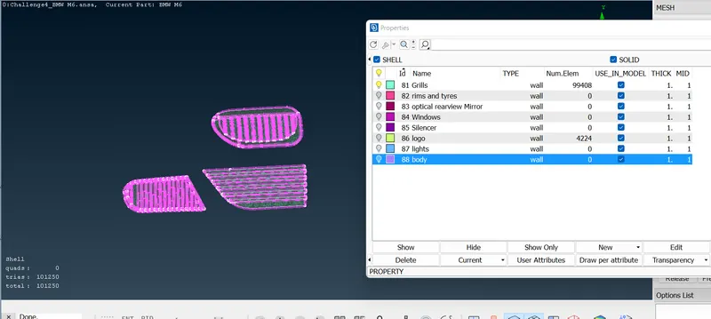
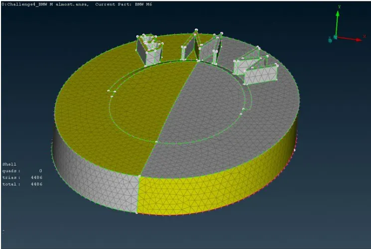
Go to Perimeters - Length - Perimeters, the whole geometry can be selected with the box select tool. After selection, the middle mouse button is pressed and mesh length (2mm) is entered
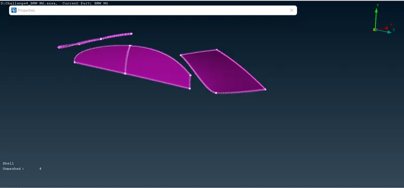
The same process is repeated for Perimeters as well. Note: While selecting edges for perimeters, the edges which are in contact with other PIDs are deselected.
The mesh is generated for the following parameters using the spot mesh, this is done by going to Mesh Generation - Spot Mesh - Visible The quality criteria of the meshed elements
are checked by switching over to the hidden.
Once we completed the half symmentry topo clean-up and surface meshing we have to use transform option - copy entities - select 3 nodes - apply - finish. This option is
used to create symmentry.
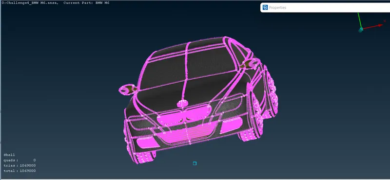
Freeze option is used to freeze the meshing because each and every part having different meshing length so this option is used to hold the mesh part.
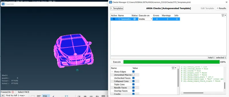
Once we complete the Surface meshing for the car and then the wind tunnel is used for CFD simulations, and has to be created in ANSA. The wind tunnel is a cuboid,
and the car is placed inside it. The inlet of the wind tunnel is 4 times the characteristic length of the car from the front of the car, the outlet of the wind tunnel is 6 times the characteristic
length of the car from the back of the car. The height of the wind tunnel is 3 times the characteristic length of the car from the top of the car. While, the width of the wind
tunnel is 1 time the characteristic length of the car from the sides of the car.
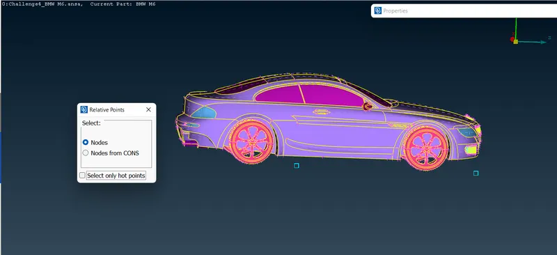
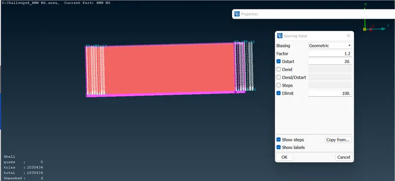
In order to create one or more meshing the surface mesh unfortunately deleted. So, we have to use spacing input option it is used to create the required mesh
size by using macros and perimeters length.
The mesh is generated for the following parameters using the spot mesh, this is done by going to Mesh Generation - Spot Mesh - Visible The Mesh quality was not
checked as quality of elements at the boundaries do not matter as no data is obtained near the planes.
using: TOPO - Points - Relative These points were joined to form a linear curve using: TOPO -Curves - Create The curves were used to create surfaces using:
TOPO - Faces - New This is the final result wind tunnel image:
A variable element length is required for these edges, as they join the lower, more finer mesh region with the upper, less fine region of the wind tunnel. Hence, mesh
lengths are uniformly increased from the lower surface (20mm) to upper surface (100mm), with a factor of 1.1. This is done by going to: C. Mesh - Perimeters - Spacing - Manual - with the following settings, and selections.
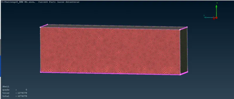
store the mesh length:
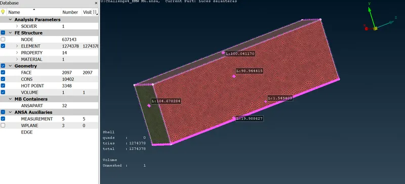
Conclusion:
Finally, We have successfully completed topology clean-up on the given BMW car model and resolved single cons and removed all overlapped surfaces.
Successfully generated surface mesh, which is pre requisite for volumetric mesh and created wind tunnel and meshed it. Also learned what is volumetric mesh
and how to performed volumetric mesh. Thus, we have successfully generated volumetric mesh for the give BMW car model.
Drive link: https://drive.google.com/file/d/1YOfQooIdIV5LeGB_gb9Mra18yxv4OpmU/view?usp=sharing