Week 4 Challenge
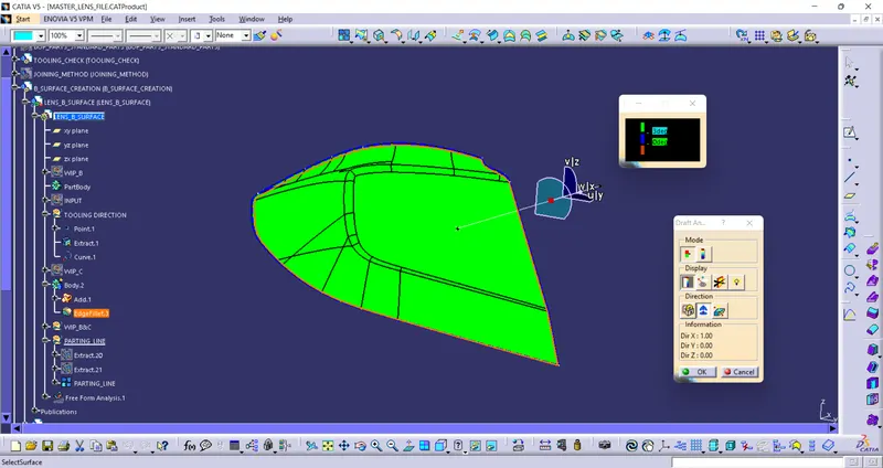
1. Tooling direction: Tooling direction is the axis along which the core and the cavity are being parted out after the mould is being injected or manufactured. Generally, there are more than one tooling direction in the industrial purpose for a component given the features and the undercuts being provided. Also, the draft angle are provided on basing the tooling direction as reference axis, hence, the tooling direction is one of the primary steps in developing the component.
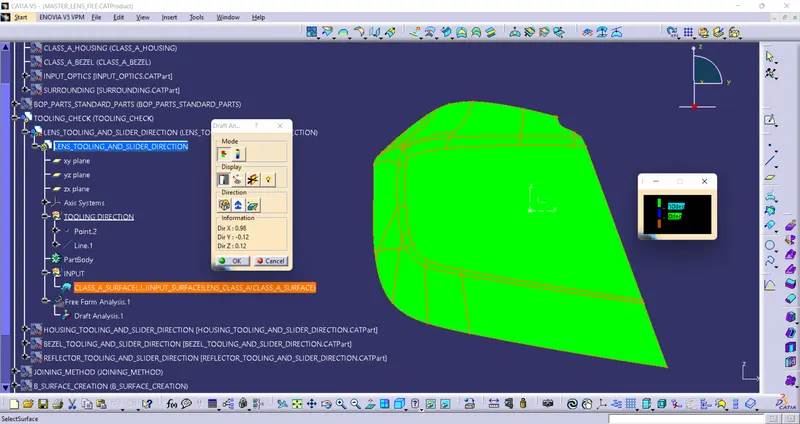
2. From the given class A surface, we are defining the tooling direction. Generally, for plastics design an angle of 3 degree and for sheet metal 10 degree is the optimum radian. But since here we are asked for 10 degree, after creating the tooling direction, we are adjusting the compass for tooling clearability. Hence, this way we obtained the given class A surface with 10 degree draft.
3. In plastic injection molding, a parting line is where two halves of a mold meet when closed. A plastic product formed by the injection mold is divided into two parts, and the line separating the product is called the parting line. Plastic is then injected at high pressure into the mold, and it solidifies with any surface features or defects in the mould. So in the case of the parting line, it will appear as an ever slightly raised line on the surface of the part. It is almost impossible to completely avoid or eradicate the parting line, but the effect can be reduced somewhat through the following solutions: camouflage the line by incorporating it with other parallel or linear design features; locate the parting line under a protruding feature like a rim or cap; disguise with rough surface textures and matte finishes; sand the lines smooth and repainted afterwards. Secondary operations to remove parting line flash including hand trimming, vibratory tumbling, media blasting and cryogenic deflashing.On most occasions, the parting line of a molded product is perpendicular to the opening direction of the mold used to make the product. When the machinist opens the mold and removes the cooled and solidified part, the moving half of the mold moves and separates from the fixed half (which is stationary).
4. B surface and part creation from the given Class A surface.
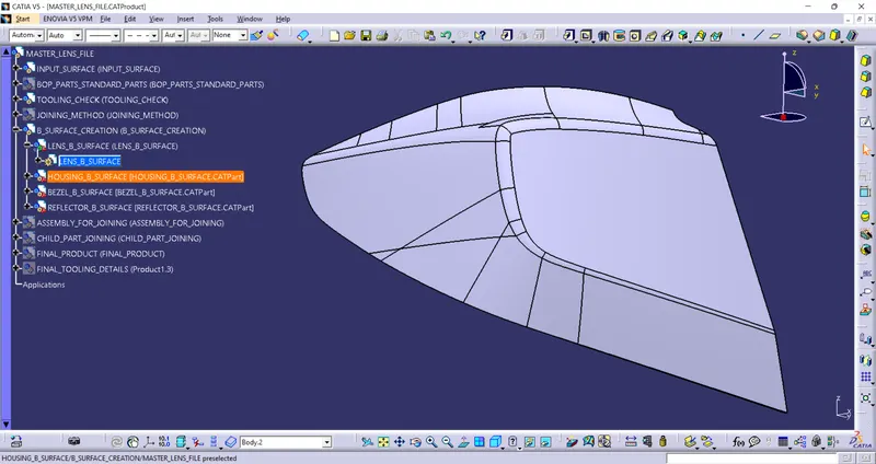
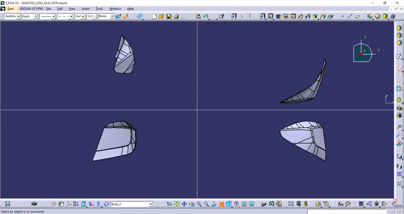
5.
Parting line for the core and cavity lens mould.
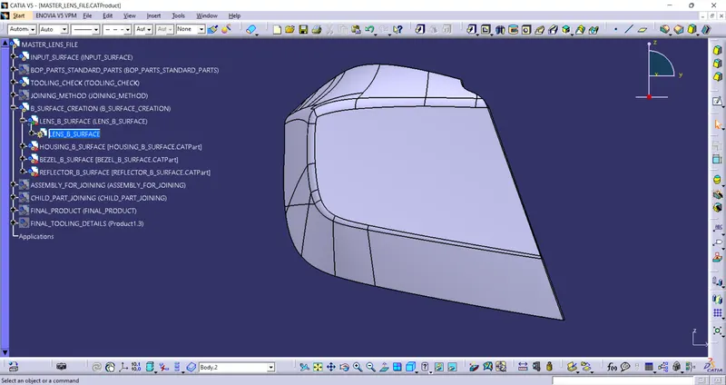
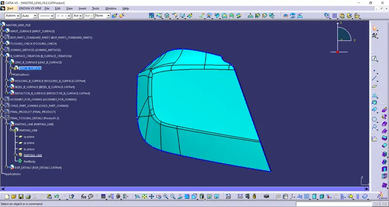
6. Prepare a report on how you have created the part and how did you approach creating a parting line and doing draft analysis.
PART MODELING:
The part modeling has been carried out by the following procedure,
1. The initial class A surface is offset by 4mm and then the surface patches are fixed.
2. From the class A as reference and with the draft direction as 3 degree, the C surfaces are developed using the sweep command.
3. Then the B surfaces are extrapolated and ensured that they intersect the C surface swept from class A.
4. Then they are trimmed together and then joined together with the Class A surface.
5. The surface is closed in the part body to obtain the final part from the class A.
6. Fillets to the edges are provided for smoother surfaces.
DRAFT ANALYSIS AND PARTING LINE:
The draft analysis is carried out from the part model for a 3 degree draft.
The parting line is chosen from the surface by the factors considered as,
1. The parting line is visible from the perpendicular axis of the tooling direction.
2. From the shape of the component, the surface has a cavity and then this surface is below the parting line.