Week 4 Challenge
1. The tooling direction is the direction where mold open and closed. This is maain axis of the injection mold in which the direction of core and cavity lie and the open and closed in this direcction.
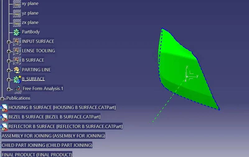
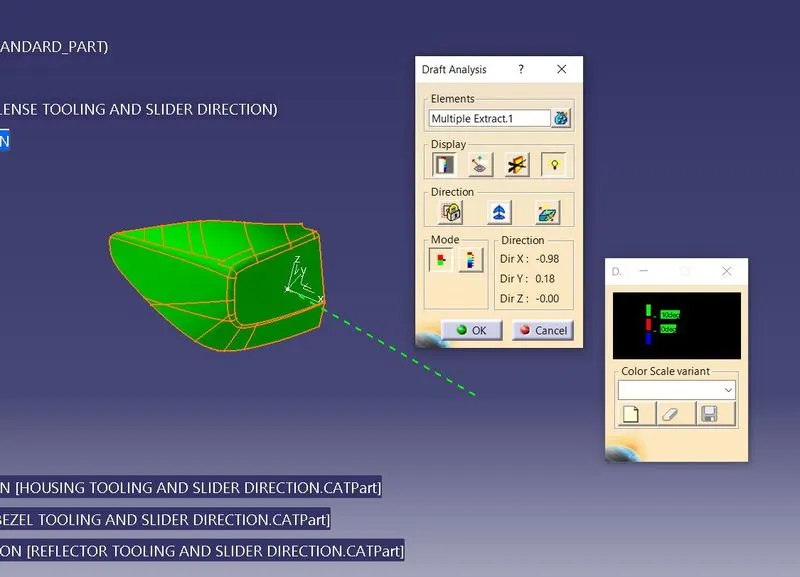
2. The green line shows the maain tooling direction of the lense ( Class-A sorface) and we keep the draft angle 10 degree.
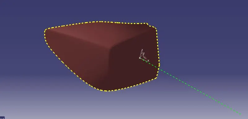
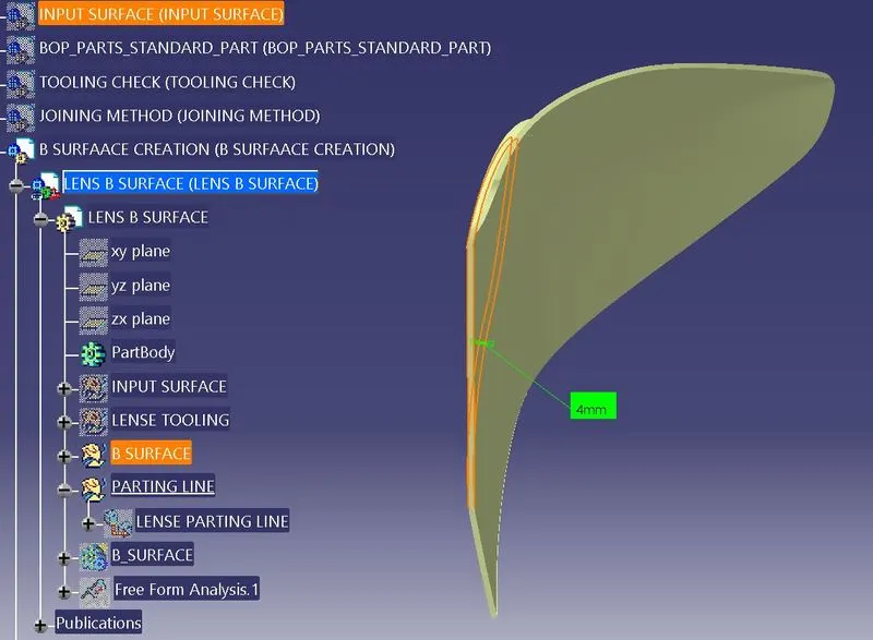
3. The parting line is that line where core and cavity plate match at a single plane or surface, This plane or surface is called pating plane or parting surface. In the below image yellow line shows the parting line of the mold r product.
4. This is closed B surface which I have to created and the wall thickness is 4mm which is shown on the below image.
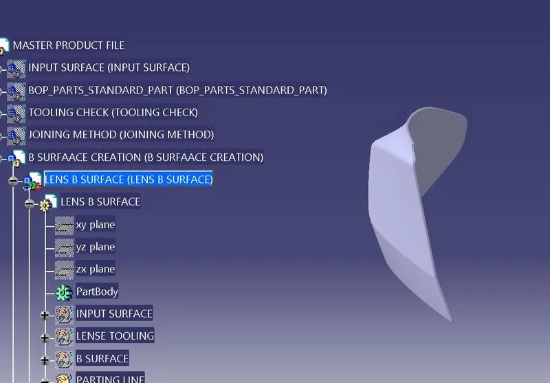
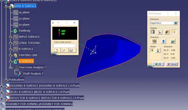
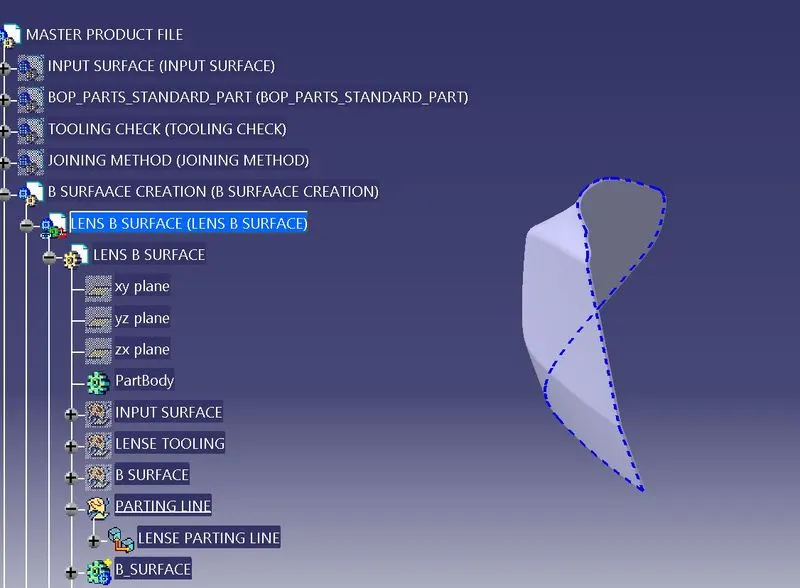
5. The parting line of the thickened lense which show in blue colour.
6. Frirst we have to create master product file and also follow the tree structure which industries has use. Now copy the input class A lense in the input section, now create the tooling direction in GSD workbench and analysis the draft 10 degree.
Now I have to join this surface with 0.001 tolerence and then copy it new WIP section, now using his surface, I have to create B class surface through offset command, there are some error show so I have to close this surface using multisection surface command, Now again creating C surface with 3 degree draft with tooling direction cand closed the all surface under GSD workbench command.
Insert new body and theen go to part workbench and using closed command make aa solid body aand checking parting line and draft anaalysis which is shown in below image.
I have also publish A class, Tooling direction, parting line under their respective tree structure.