Week 4- Challenge
AIM :
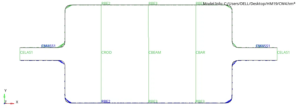
Create 1D elements on the following component with given cross-section and DOF
a. Rod element:- with only translational DOF and RBE2 link
Cross-Section: BOX- Dimension a= 12 mm
dimension b=10 mm
Thickness t= 0.75 mm
b. Beam element:- with all DOF and RBE3 link
Cross-Section: I Section- Dimension a= 8 mm
Dimension b= 10 mm
Dimension c= 8.5 mm
Thickness t1= 0.75 mm
Thickness t2= .6 mm
Thickness t3= .6 mm
c. Bar element:- with only x and y DOFs With RBE3 link
Cross-section: CROSS section- Dimension DIM1= 5 mm
Thickness DIM2= 1.2 mm
Dimension DIM3= 10 mm
Thickness DIM4= 1.2mm
d. & e. apply the mass of magnitude 10 with RBE2 link
f. Join the two components with Spring elements
Procedure:
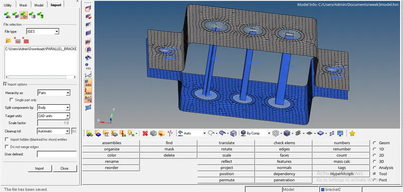
Import the given IGS file in to the Hypermesh from model import option shown in the fig1.01
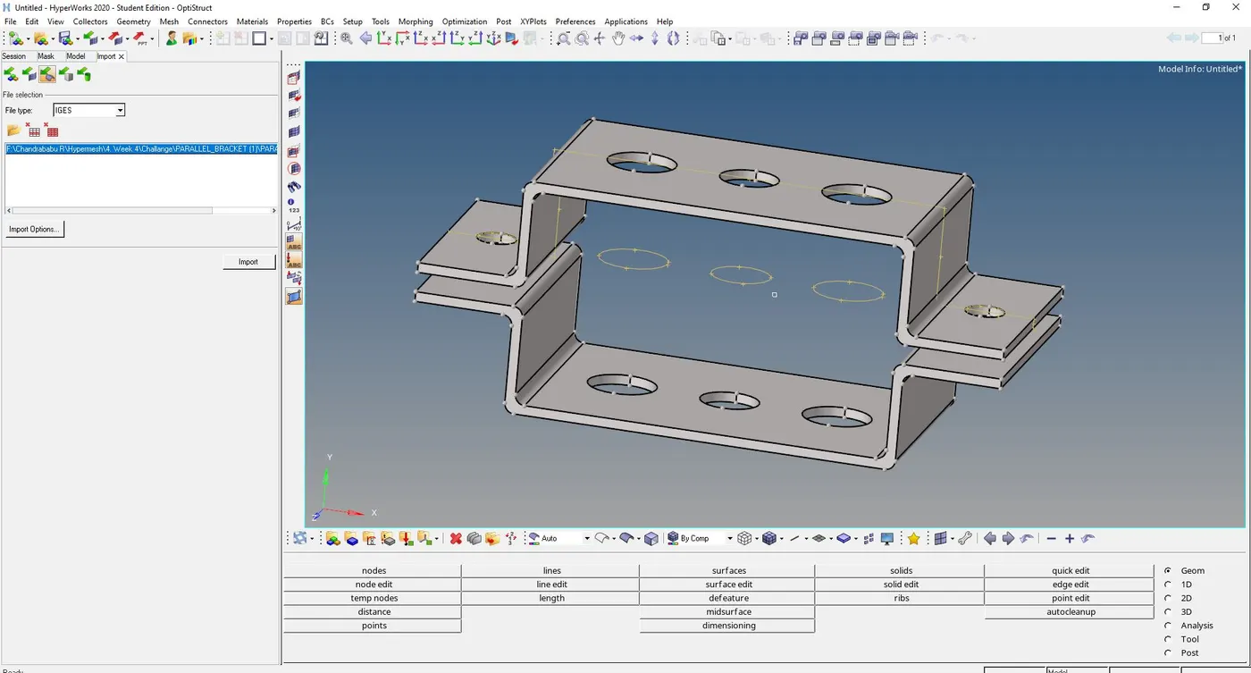
1. MidSurface Extraction: For the given component extract the midsurface from the given slide which is a sheet of 5mm thickness.
for extraction of mid surface Auto midsurface (Geo>midsurface>Automidsurface) and select the surface, click extract so that it will create midsurface. We can change the type selection by Extraction option shown in the fig.1.1. and fig1.2 show the mid surface of given Comp.
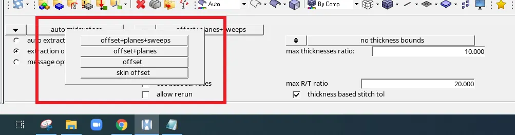
Fig.1.1: Extraction Options
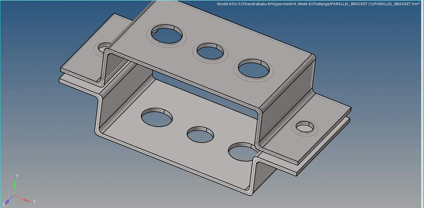
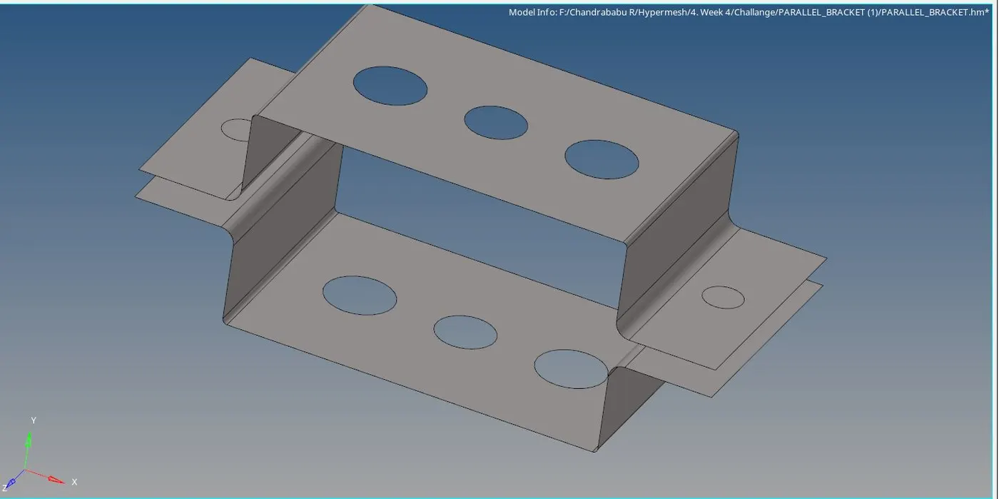
Fig.1.2: Mid Surface
2. Assigning Property: Whatever extracted surface is in a single component. so that organization is required as per the thickness. to do that use the tool Organize (tool>organize) select the type and Dest Component and click on move. similarly for any type of the entity can move Show in the fig2.1.
Create the washer zoon by using Geom>Quick Edit>Washer split by selecting edges. we can see that washer splits in the fig2.1
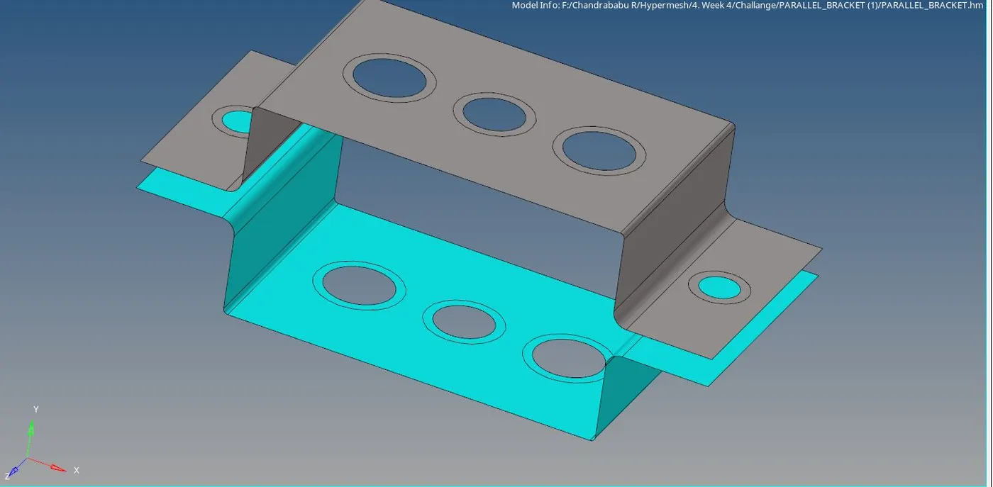
Fig.2.1: Assigning Property
3. Meshing: Here 2D meshing done by Automesh (2D>Automesh)
Select the surface (Shift+Left mouse button And Drag) and give the element size, Click mesh the following fig3.1 shows mesh elements
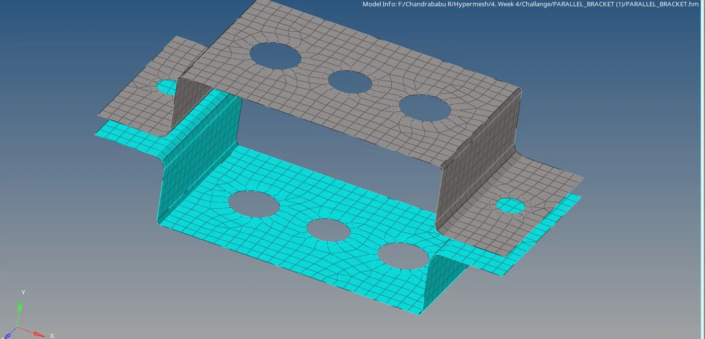
Fig.3.1: Meshing
4. Creating RBE2 and RBE3 And joining:
RBE2: is the 1D element with infinite stiffness also called Rigid element
Create RBE2 by Regids(1D>Rigids). For the location we can select as a noe or multiple nodes with degree of freedom shown in the fig 4.1

Fig.4.1:RBE2
RBE3: RBE3's are interpolation constraint elements, where the motion of a dependent node is defined as the weighted average of the motions of a group of independent nodes. The dependent degrees of freedom and weighting factors can be specified or automatically calculated based on the geometry.
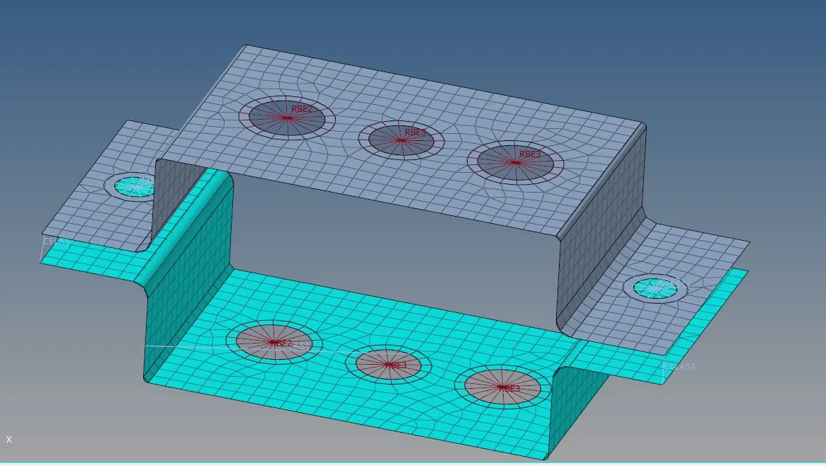
Join all respective nodes of RBE2 and RBE3 as per memstion cross section with locations for Bar and Beam we can use bar (1D>bar), inside we have defined the type of element from CBAR, CBEAM.
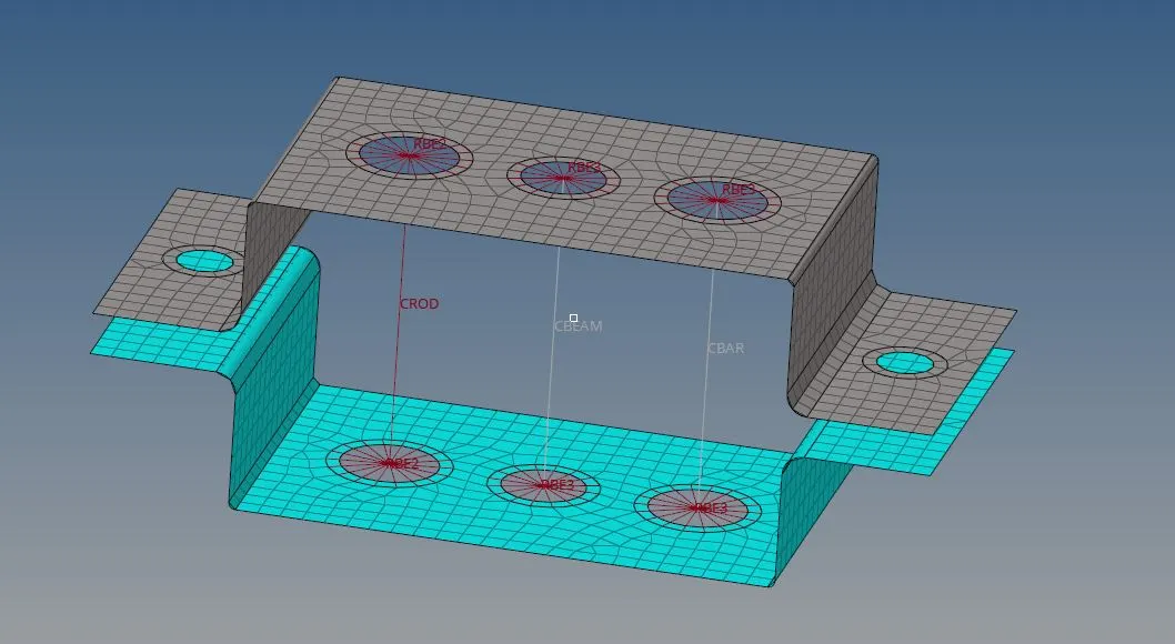
cross-section and DOF:
LS REQUIRED :
a. Rod element:- with only translational DOF and RBE2 link
Cross-Section: BOX- Dimension a= 12 mm
dimension b=10 mm
Thickness t= 0.75 mm
1) Create RBE2 links. Go to 1D->rigids->Select the nodes->Create
2)To create box, go to hyperbeam->standard section->select hyperbeam from drop menu->thinwalled box from bottom drop menu->create.
3)Hyperbeam will open. Give the dimensions of your section and click model view to open hypermesh.
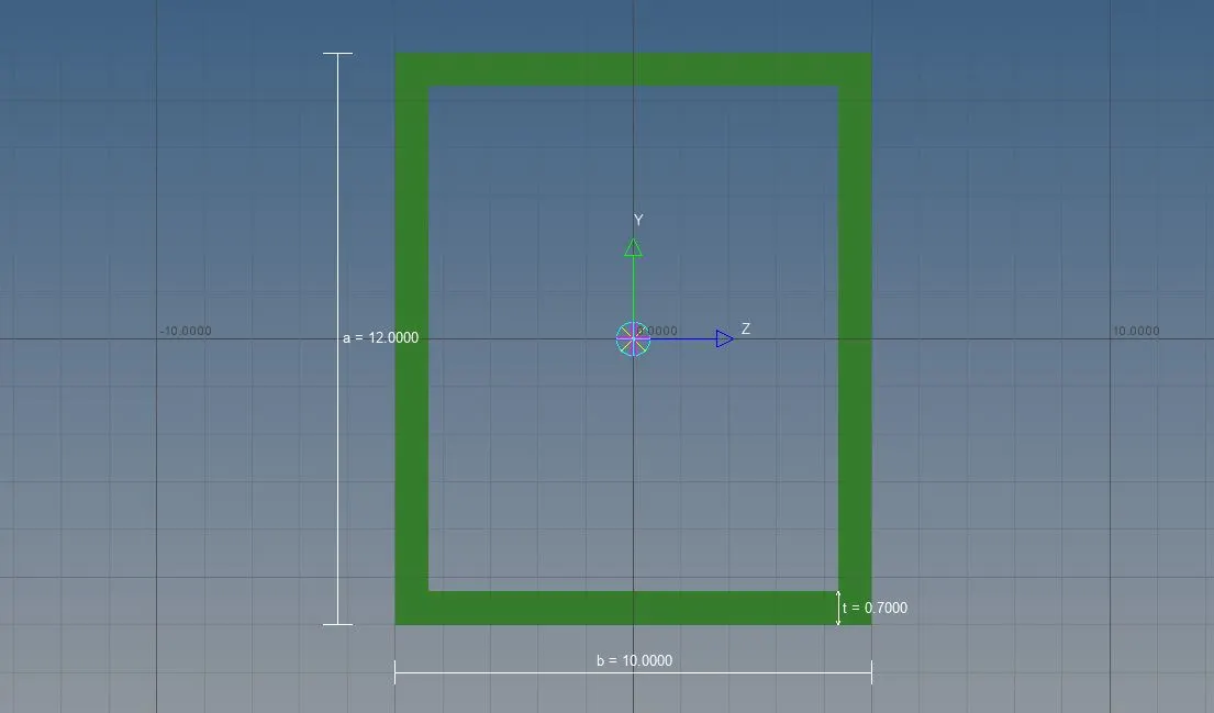
4)Create a new property of rod. select card image as PROD. Assign the beam specification as created in hyperbeam.
5)Go to 1D->rods, select property that you created. Change element types to CROD, select the nodes.
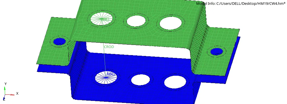
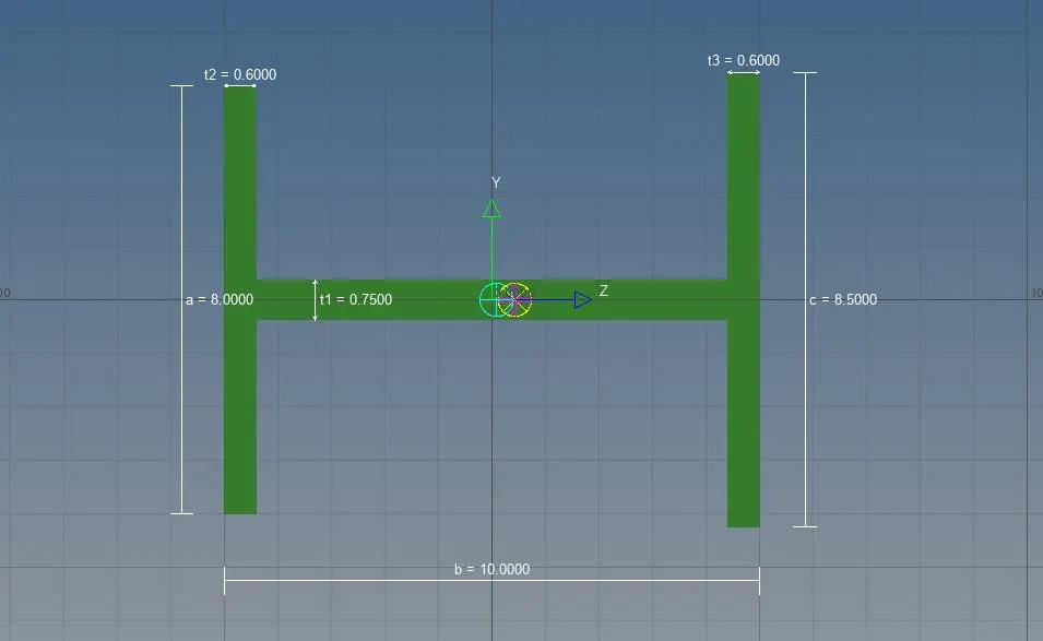
b. Beam element:- with all DOF and RBE3 link
Cross-Section: I Section- Dimension a= 8 mm
Dimension b= 10 mm
Dimension c= 8.5 mm
Thickness t1= 0.75 mm
Thickness t2= .6 mm
Thickness t3= .6 mm
1)Create RBE3 elements. Uncheck all DOFS. Select the nodes and create.
2)Go to hyperbeam->create->standard selection->Hypermesh->I section. Give the dimensions and go back to hypermesh.
3)Specify the dimensions in the new created property. Card image PBEAM. Go to bars, select the nodes and give property beam, change element types to CBEAM. create the element.
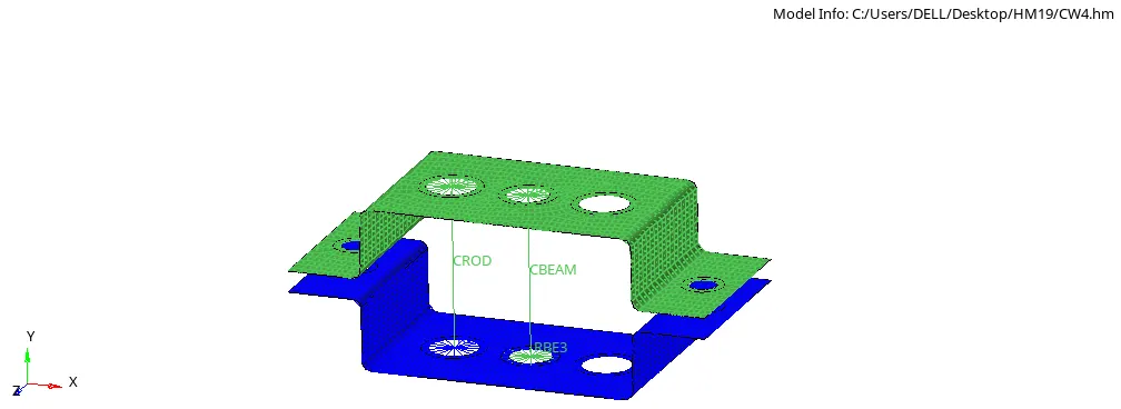
c. Bar element:- with only x and y DOFs With RBE3 link
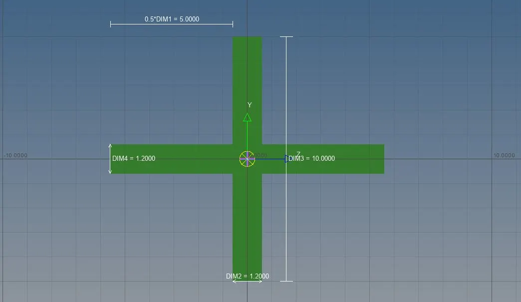
Cross-section: CROSS section- Dimension DIM1= 5 mm
Thickness DIM2= 1.2 mm
Dimension DIM3= 10 mm
Thickness DIM4= 1.2mm
1)Create RBE3 links as mentioned above and deselect x and y dofs.
2)Create the cross figure in hyperbeam and give the dimensions as above mentioned.
3)Import the porperty of new created element. Change the card image to PBAR.
4)Go to 1D->bars->select the property as bar->elemen types as CBAR->node A->node B->N1,N2,N3.
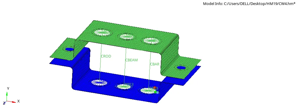
create different properties for Beam,bar and rod and assign sections respectively shown in the fig below.
V) SPRING:-
1)Create a new property spring, give card image as PBUSH. Assign the values.
2)1D->springs->elem type-CELAS1->property-spring->select nodes
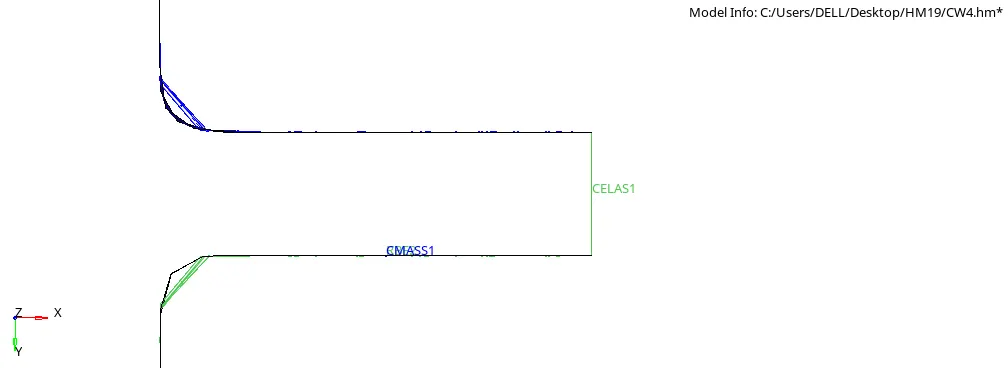
FINAL IMAGE
RESULT :