Week 4- Challenge
OBJECTIVE: TO Create1D elements on the following component with given cross-section and DOF
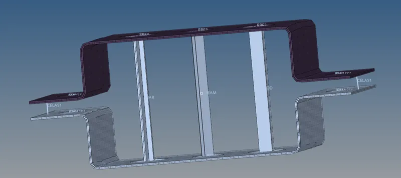
a. Rod element:- with only translational DOF and RBE2 link
Cross-Section: BOX- Dimension a= 12 mm
dimension b=10 mm
Thickness t= 0.75 mm
b. Beam element:- with all DOF and RBE3 link
Cross-Section: I Section- Dimension a= 8 mm
Dimension b= 10 mm
Dimension c= 8.5 mm
Thickness t1= 0.75 mm
Thickness t2= .6 mm
Thickness t3= .6 mm
c. Bar element:- with only x and y DOFs With RBE3 link
Cross-section: CROSS section- Dimension DIM1= 5 mm
Thickness DIM2= 1.2 mm
Dimension DIM3= 10 mm
Thickness DIM4= 1.2mm
d. & e. apply the mass of magnitude 10 with RBE2 link
f. Join the two components with Spring elements
PROCEDURE:
1.open the hyperworks import the given model which will be in iges format.
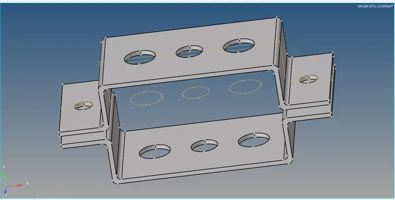
2.from geometry select midsurface and do midsurfacing for top portion and rename it as brac1.
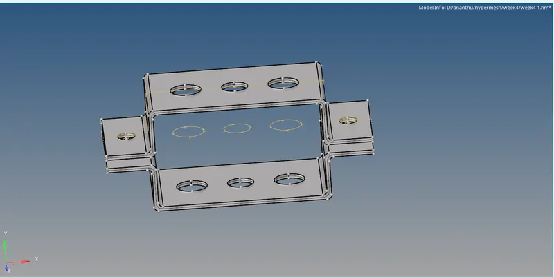
3.create a component named brac2 for the 2nd portion of the bracket to be mid surfaced.
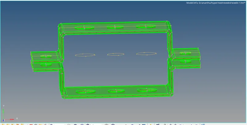
4.delete the solid entities and keep only the midsurface.from organise menu move the midsurfaced area to the created brac2.
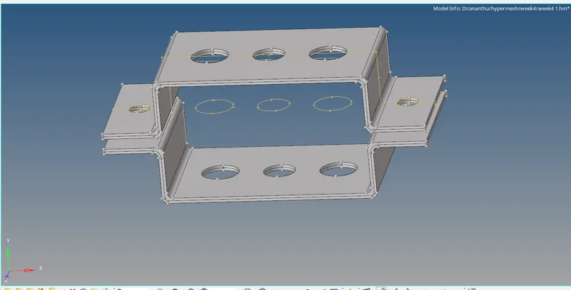
5. after removing the solids and assigning the second midsurface to the component we created we can change the colour assigned by us to the brac2.
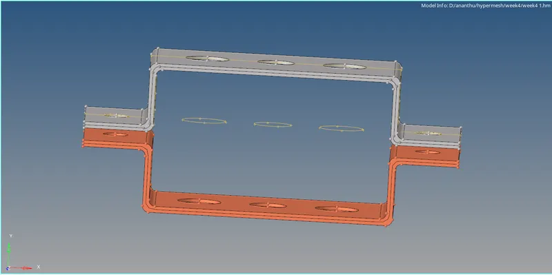
6. remove all surfaces except the midsurface obtained.
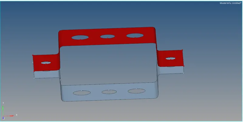
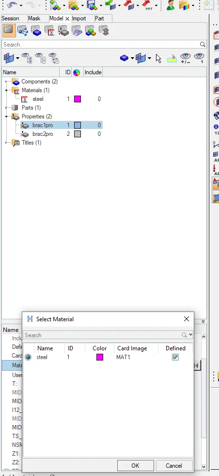
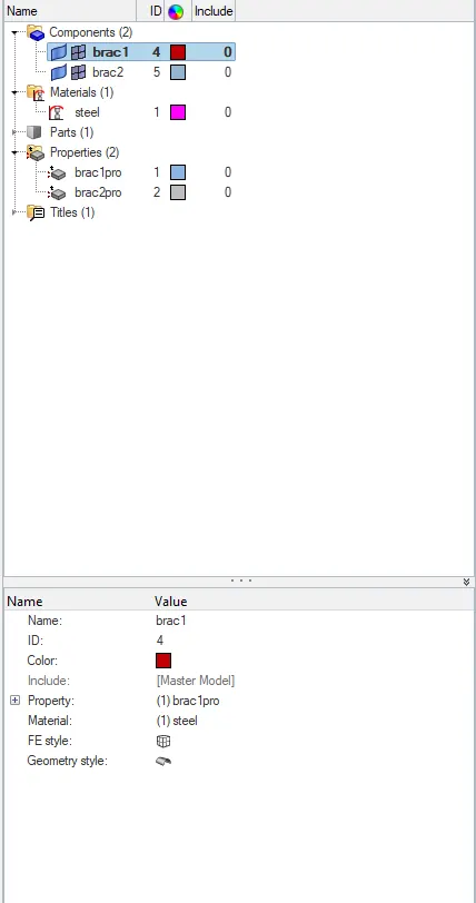
7.create the material required to make the surface 2D .steel has been selected with card image as MAT1 and also we created two new properties for bracket 1 and 2 then we assigned their material as steel with 2 and 2.5 thickness respectively.then we select properties for one and two brackets which will automatically update material as steel from properties assigned.
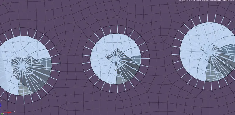
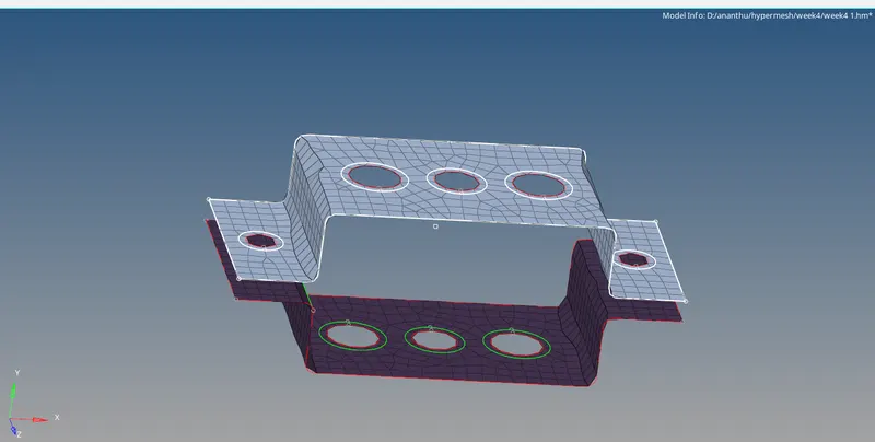
8. add washer splits and do 2D mesh .
9.at point A rbe2 link has been made with only transilational degrees of freedom.
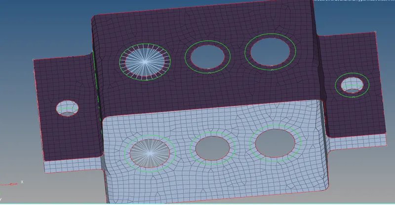
10. at point B and C rbe3 links are made .All degrees of freedom at point B and only x and y axis's at point C.
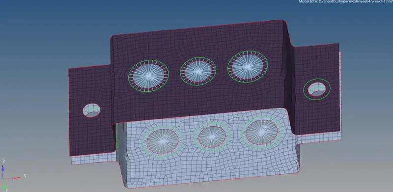
11.at point d and e create rbe2 links and from mass set mass magnitude as 10 and create a node to apply the mass at point d & e respectively.
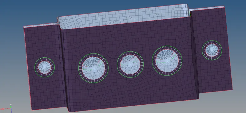
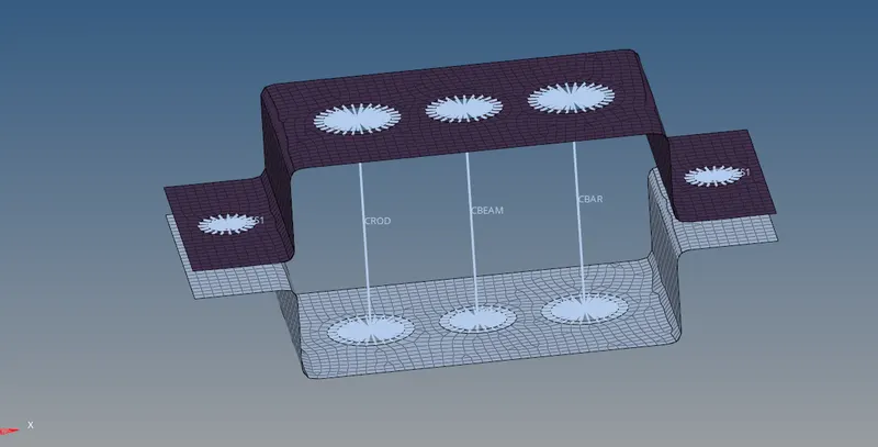
12.at point a b and c create rod beam and bar respectively.
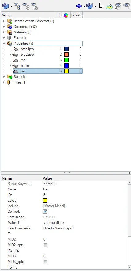
13.create properties for rod ,beam and bar set card image as prod, pbeam and pbar respectively.
14.select material for rod beam and bar as steel and select there corresponding beam section.
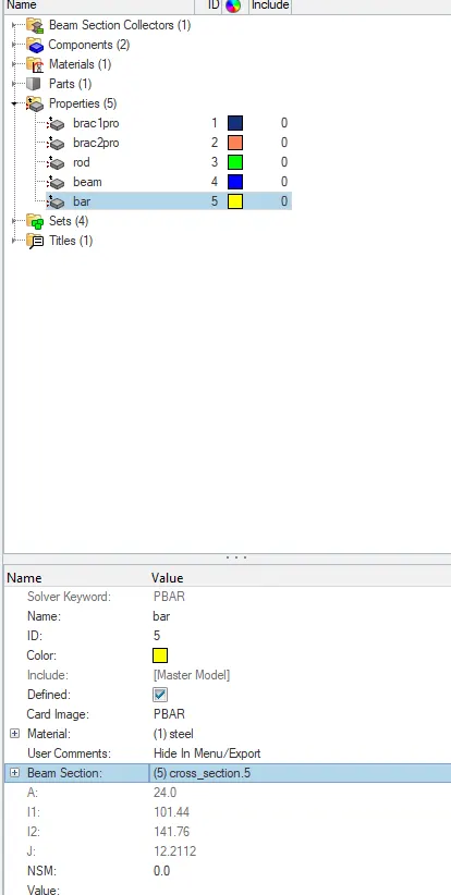
15.update the details of rod beam and bar in the model and update it.
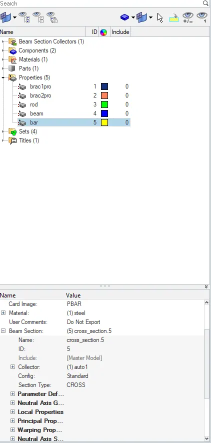
16.select properties of the beam bar and rod and update it to get the I SECTION CROSS SECTION AND ROD.
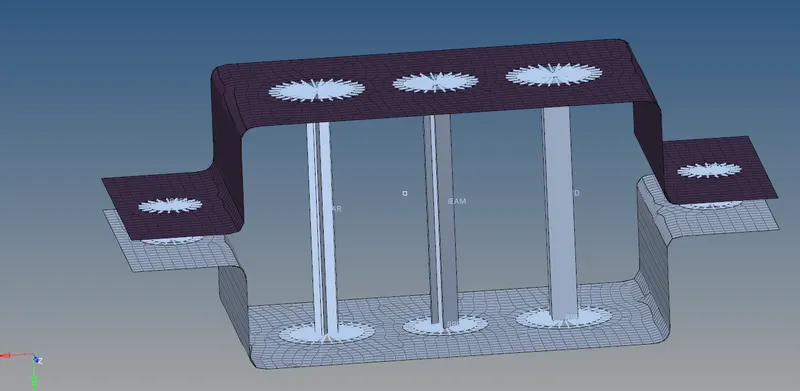
17.at point f elastic components where made from selecting spring menu and selecting 2 nodes.
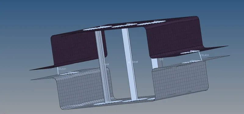
CONCLUSION: following cross sections where made on the given model with the given dimensions.