Week 12:Project 2-Meshing of Rear Wheel Holder challenge
OBJECTIVE:
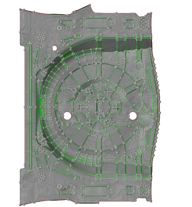
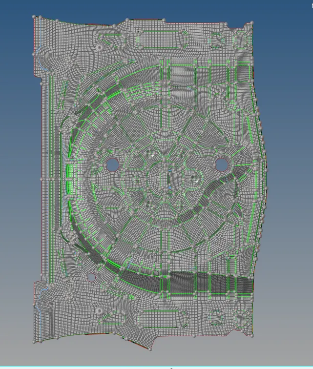
To mesh the component given below and assign thickness.
Target Element Length = 5 Units
| S.N | Quality Criteria | Value |
| 1 | Aspect Ratio | 5 |
| 2 | Skewness | 45 |
| 3 | Warping | 15 |
| 4 | Taper | 0.5 |
| 5 | Min. Length | 2 Units |
| 6 | Max. Length | 8 Units |
| 7 | Min angle Quad | 45 |
| 8 | Max angle Quad | 135 |
| 9 | Min angle Tria | 20 |
| 10 | Max angle Tria | 120 |
| 10 | Tria % | 10 |
PROCEDURE:
1. ANALYSIS OF THE COMPONENT
- the given component is the floor panel of a car.
- the component is sheet metal with same thickness.
- the component has a thickness of 0.75 .
- the given component has many circular and converging areas so the tria percentage will be high.
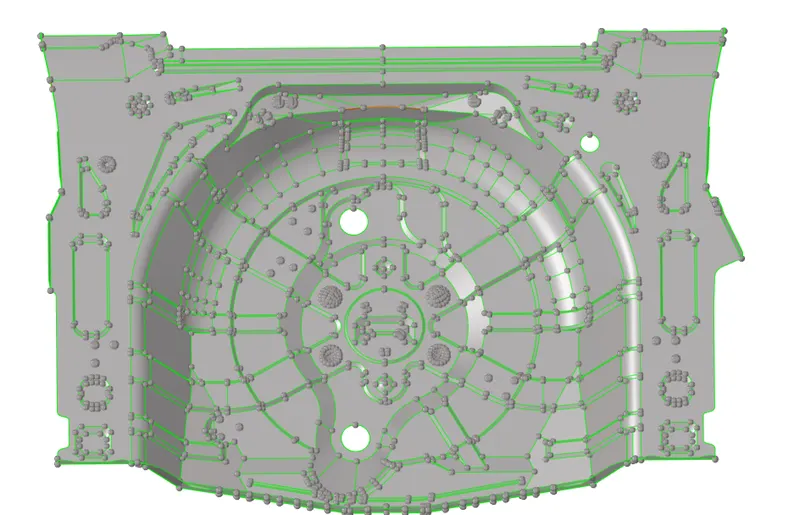
2. GEOMETRY CLEANUP
- model has to be uploaded to hyperworks and has to be checked for deformations.
- we can see many components there we have to organise it into one component.
- gaps found has to be filled using filler surface option or possible gaps can be toggled or surface can be created.
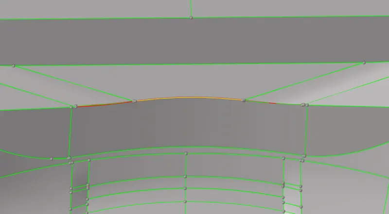
- we can observe that some surface has been not created we have to create the surface by ruled option.
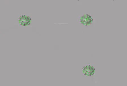
- small circular components can be deleted since it fails for the criteria.
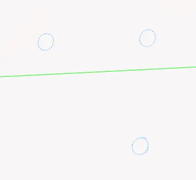
- these circular areas can be deleted and can be filled using unsplit option in quick edit.
3.MIDSURFACE GENERATION
- we can use auto midsurface to extract the midsurface and also we can go for manual mid surface.
- since it is a sheet metal and of uniform thickness we can go for auto extraction.
- go to geometry>midsurface>go to extraction option>change to offset+planes+sweeps.

- then go to extraction option and select the surface to be extracted by face and put the option in closed solid and press extract.

- midsurface will be created.
4.CLEANING OF MIDSURFACE
- deformations can be corrected by using toggle line option or by replacing points option from quick edit panel.
- if there is no connection between midsurfaces obtained we can extend it to make connections.
- if any area fail for minimum length we can even toggle some lines.
- after the mid surface extraction some areas will not be perfect we can make it perfect creating surface by using ruled option in surface.
- geometry>surfaces>ruled>create.

- surface will be created.
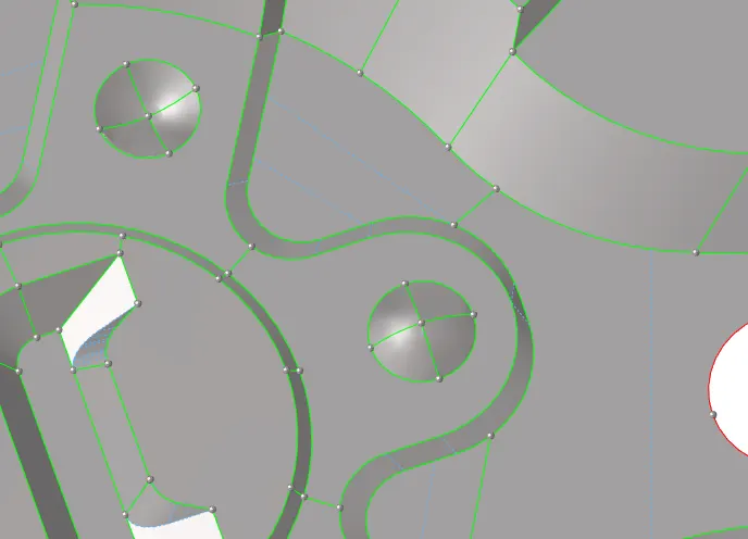
- some circle areas will be too bad.
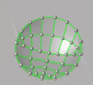
- circles has to be made perfect for meshing,feature lines should be perfect.
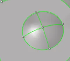
- we can do it by positioning the correct surface to the required area.
- tool>position>select nodes and set the direction properly.
- select the area to be positioned and press >position.

5.QUALITY CRITERIA
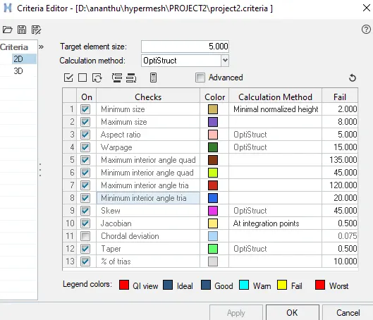
- criteria has to be set according to the objective.
- preferences>criteria file settings> assign values>apply.
- save the settings for future usage.
6.MESHING
- after assigning the quality criteria we do meshing.
- go to 2D>AUTOMESH.
- keep element size as 5.
- mesh type should be mixed and the setting should be in keep connectivity.
- size ,skew and align should be checked for good mesh.

- select the surface to be meshed and press mesh.
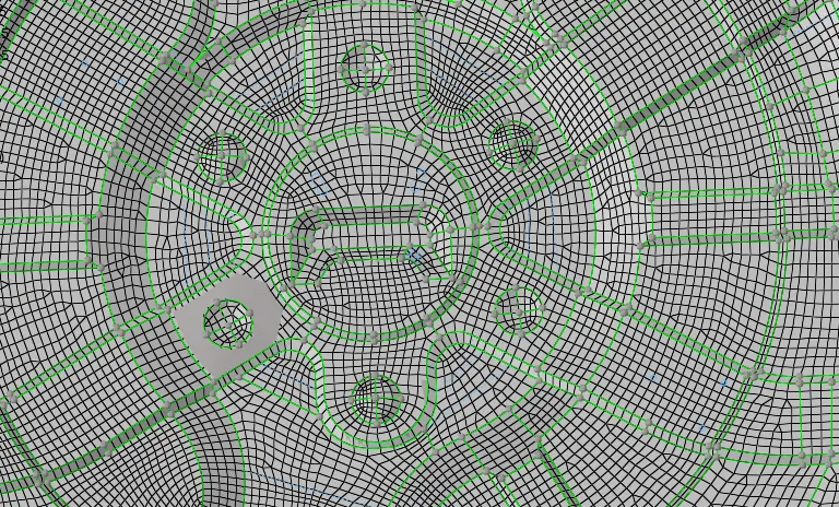
- mesh obtained will have trias.
- we should reduce maximum possible trais.
- we can drag the possible ones out or combine the opposite trias.
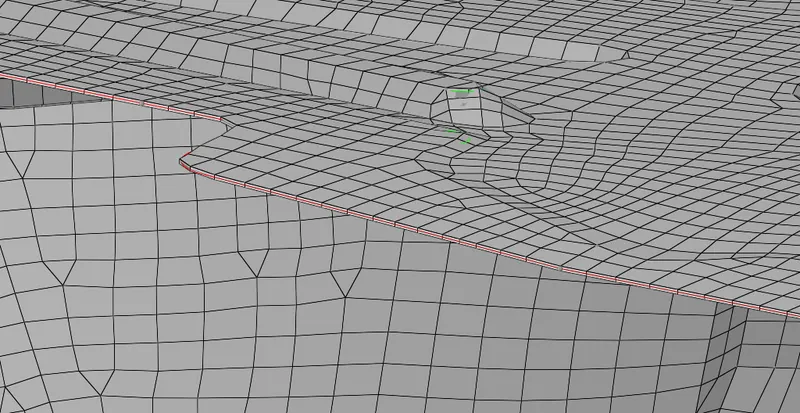
- no trias should be there at the corners and free edges in our mesh.
- opposite trias shouldnt be there in our mesh.
- no trias should be there at the fillets and hemmings if there reduce it to minimum.
- no rotational quads should be there in our meshed parts.
- connectivity of elements has to be ensured.
- for good mesh flow and proper mesh we should do smoothing.
- 2D>quality index>smooth.
- QUALITY INDEX option is used to make our mesh a better one and to reduce errors and trias.
- Place node: Used to manually move a node.
- Smooth: Used to smooth the elements to get better mesh flow.
- Swap edge: To swap the edges of the element.
- Node optimize: Place the node in an optimize position in order to reduce the errors.
- Element optimize: Optimize the elements in order to reduce errors.
- Split\collapse edges: Used to split the elements.
- Drag tria elements: To move the trias in the mesh.
- Split quad elements: To split the quad elements.
- Combine tria elements: Used to combine two tria elements.
7.CONNECTIONS
- ensure that the elements are connected each other.
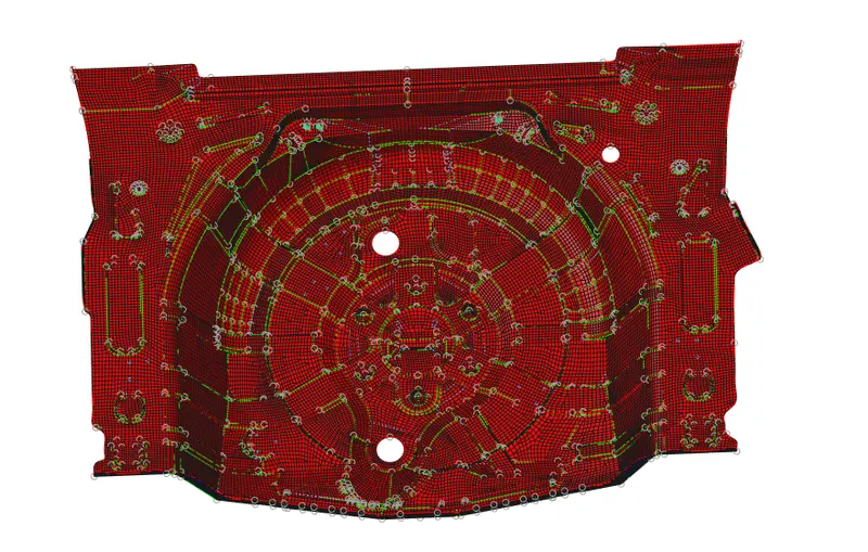
8.NORMALS AND FREE EDGES
- go to tools >normals>displayed 2D elements>colour display >press display.
- if any one side has a combination of colours then we have to press adjust for adjusting it.
- by doing so almost all errors will be cleared if not select manually and clear it.
- press reverse to exist the normals.
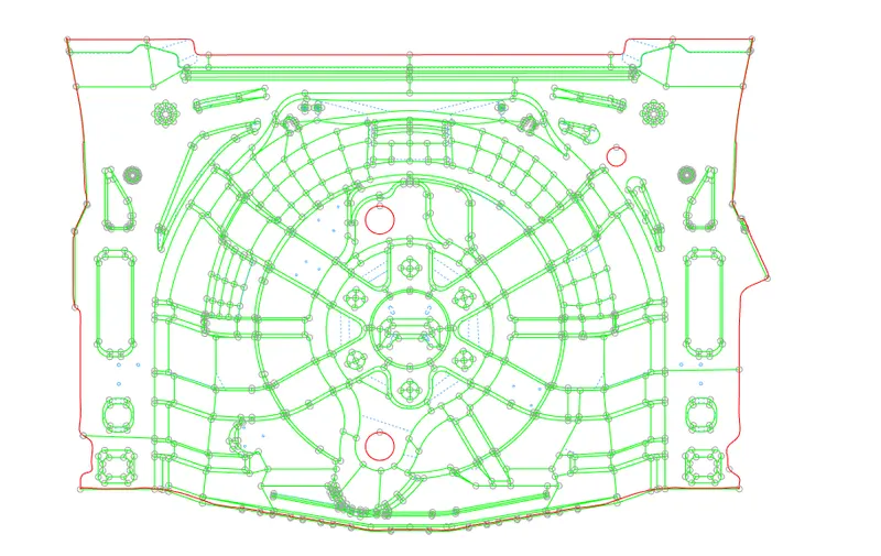
- to check for free edges ,
- go to tool> edges.
- Choose elements and then select the whole elements.
- Click on find edges.
- Now hide other parts and make edges mesh only visible.
- Now check if there is any red line on the areas other than the boundary.
- if so correct it.
9.ASSIGNING THICKNESS
- after the meshing is done we can assign the thickness.
- since the components have the same thickness we can assign thickness in one go.
- we need to assign the property for it.
- create a property card for the component.
- then press on the property card and assign the thickness of 0.75 for the component.
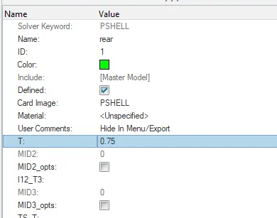
- to assign this property to the component right click on the component and press assign and select the respective thickness and press apply.
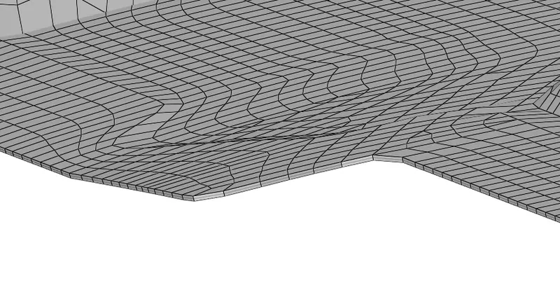
- in order to see the thickness assigned switch the view to 2D detailed element representation.
RESULT:
THE GIVEN COMPONENT WAS MESHED AND THICKNESS WAS ASSIGNED.