Meshing & Deploying 1D Connector Elements on Bracket Model using HYPERMESH
In this work, a bracket model was taken to discretize and deploy the 1D elements, to connect the two brackets. For making the connections, both RBE2 and RBE3 were used, and the two brackets were then connected using, rod, bar, beam, and spring elements. A mass magnitude 10 was also deployed.
OBJECTIVE
- To obtain the mid-surface of the bracket model.
- To discretize the model.
- To deploy the connections/1D elements.
PROCEDURE
Pre-preparation of the model for FEM
A CAD model was available of the bracket in .iges format. Using the import geometry option in Hypermesh, the model was imported into the workspace. The model had three components listed. Two of them were bracket and the other one was containing the wireframe model which was not required, and hence deleted.
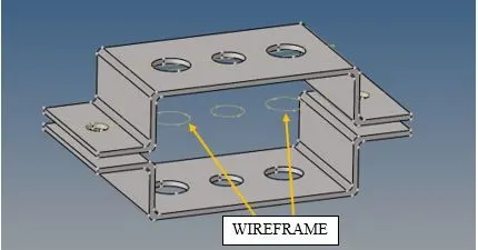
Figure 1: 3D model of the bracket.
The model was geometrically good, or it was not having any geometrical disturbance, thus mid-surface could be obtained. However, before proceeding to the extraction of mid-surface, it was required to delete the solid part of the geometry. It is because it disturbs the mid-surface that would obtain. Therefore, the solids have been deleted, at first. Also, the thickness was measured, using the ‘length’ tool in the geometrical section, which was found to be 5 units for both the brackets.
Once the model was ready for obtaining the mid-surface, using the ‘midsurface’ tool in the geometry section, the mid-surface is obtained, for both the brackets. Although the brackets were having the same thickness and material, they are put in separate components, to assign them the thickness and material separately.
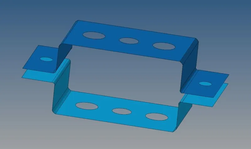
Figure 2: Midsurface obtained from the 3d model of the brackets.
Two separate colors of the brackets in fig. 2 shows that the two brackets are put in two different components. A material card was then created taking the data of steel, by clicking the right button of the mouse, in the tab area, and in the create option selecting the ‘material’ option.
Similarly, by clicking the right button of the mouse in the tab area, a separate property card was then created for both the brackets, to assign the thickness, the material and selecting the card image as PSHELL, because the kind of meshing would be a 2d mesh. The component of brackets was then assigned their respective property cards. So now the mid surface of brackets is having all of its properties assigned.
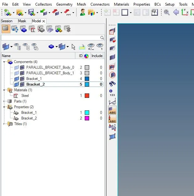
Figure 3: Separate components and properties assigned to the two brackets. Properties of steel material provided in the property.
One thing to notice in this work was that there were 5 holes per bracket. Therefore, each hole was given a washer split, as shown in fig. 4.
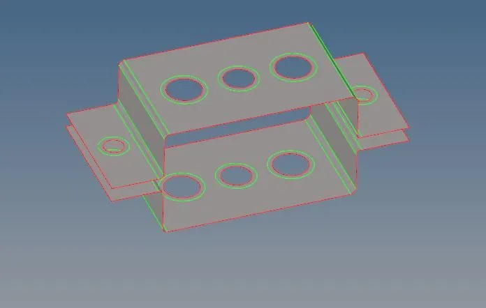
Figure 4: Washer split given to each hole.
Discretization or Meshing
Now when the mid surface is provided all the required properties, it is then ready to proceed with discretization. The parent bodies can now be deleted, but it is kept in this work for reference. The quality of the element is of utmost importance in FEM, therefore, before starting with meshing, the quality of elements required had to be provided. In the 2d section, using the ‘elem cleanup → edit criteria’ quality parameter for the element was fixed. An aspect ratio of 3, the minimum length of 1 mm, a maximum length of 5 mm, and the target length of 3 mm was provided.
Using the ‘automesh’ tool in the 2d section, at first, all the washer zone was meshed and then one-by-one each face of brackets meshed. Fig. 4 shows the meshing of the washer split region.
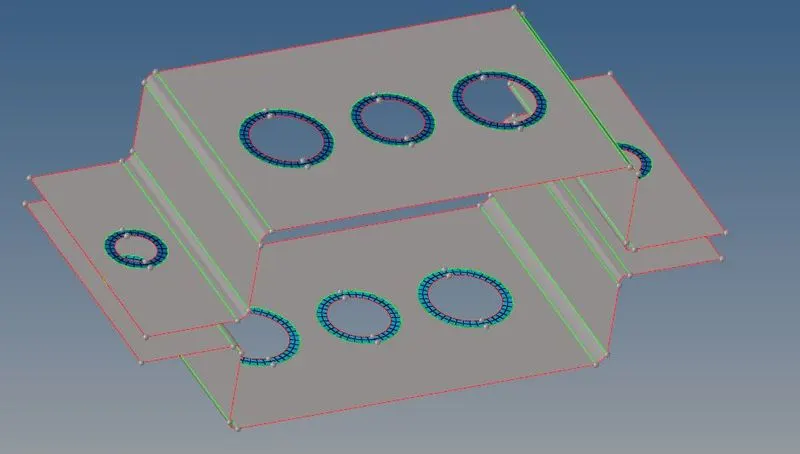
Figure 4(a): Washer split zone meshed at first.
Fig. 4(b) shows the complete meshing of the brackets. Poor mesh flow was rectified using the ‘qualityindex → cleanup tools’. In the cleanup tools section, drag tria element, combine tria element, split/collapse edge, etc. was used to minimize tria and maintain the flow of elements.
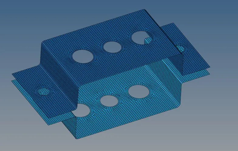
Figure 4(b): Completely meshed brackets.
Connection using 1D Elements
In this work, the requirement was to give different 1d connections to different holes. Its variation is as shown in table 1.
Table 1: Properties of different elements required that has to be placed at different holes, as shown in fig. 5.
a. Rod element: with only translational DOF and RBE2 link.
Cross-Section: BOX: Dimension a = 12 mm
dimension b = 10 mm
Thickness t = 0.75 mm
b. Beam element: with all DOF and RBE3 link.
Cross-Section: I-Section: Dimension a= 8 mm
Dimension b= 10 mm
Dimension c= 8.5 mm
Thickness t1= 0.75 mm
Thickness t2= 0.6 mm
Thickness t3= 0.6 mm
c. Bar element: with only x and y DOFs With RBE3 link.
Cross-section: CROSS-section: Dimension DIM1= 5 mm
Thickness DIM2= 1.2 mm
Dimension DIM3= 10 mm
Thickness DIM4= 1.2mm
d. Apply the mass of magnitude 10 with the RBE2 link.
e. apply the mass of magnitude 10 with the RBE2 link.
f. Join the two components with Spring elements.
Fig. 5 shows the position where the 1D elements with the above-given dimensions have to be placed.
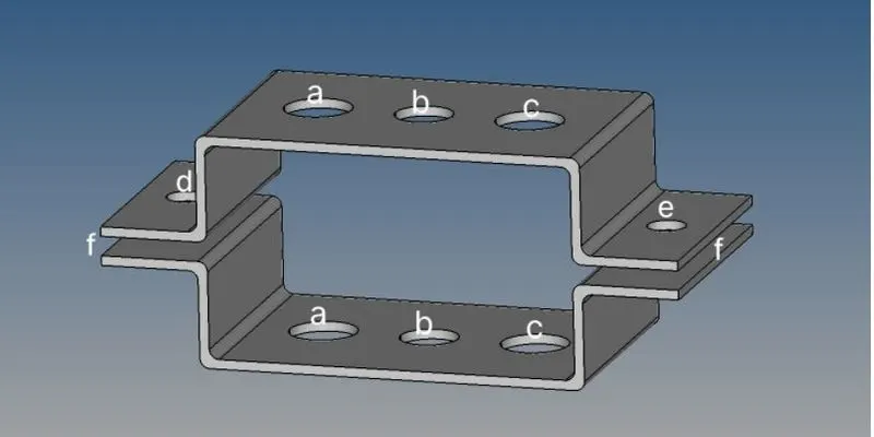
Figure 5: Model showing the position of 1D elements where it has to be placed.
Before deploying the bar, beam, and rod element, RBE2 and RBE3 cluster has to be provided in the holes, as given in the requirements, and that too with given respective dofs. Using rigids and rbe3 option in 1d section, respective clusters were deployed and kept under different components, as can be seen in fig. 6. The color variation of these clusters indicates that they are put in different components.
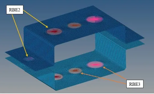
Figure 6: Positions where rbe2 and rbe3 clusters are placed.
Now as shown in table 1, it was required to place the rod element, of box cross-section, where rbe2 cluster with only translational dofs is there. To place a rod element, the ‘rods’ tool was selected in the 1d section, and two nodes, which had to be connected, were selected. A sharp line, representing a rod element was then created, as shown in fig. 7. Notice that, the rod element was again put in a different component.
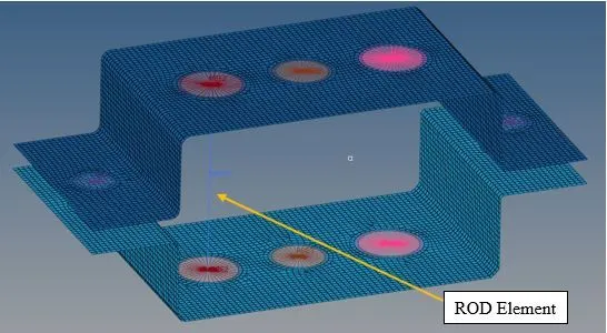
Figure 7: ‘CROD’, a rod element was created connecting two nodes.
Now the rod element is placed but it had no cross-section. For that, a ‘HyperBeam View’ window was opened, in which, under the create option, using ‘Standard Section → OptiStruct → BOX’, a box cross-section was created and provided the required dimension, as per the requirement given in table 1. It was given the name ROD. Once it is created, a model view was opened again, and in that, a new property was created. In property, card image was selected as ‘PROD’, a material was assigned as steel, and in beam section, rod cross-section was selected that was created in HyperBeam View with required dimension. Once the property is fixed, it was time to assign this property to the rod element. A component of rod element was selected, and in that the property of rod was assigned as created just before. With this, the rod element with box cross-section has been created, as can be seen in fig. 8.
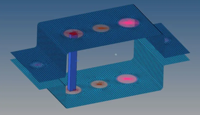
Figure 8: Rod element with box cross-section.
Similarly, the other beam and bar element with respective cross-sections was placed, as shown in fig. 9.
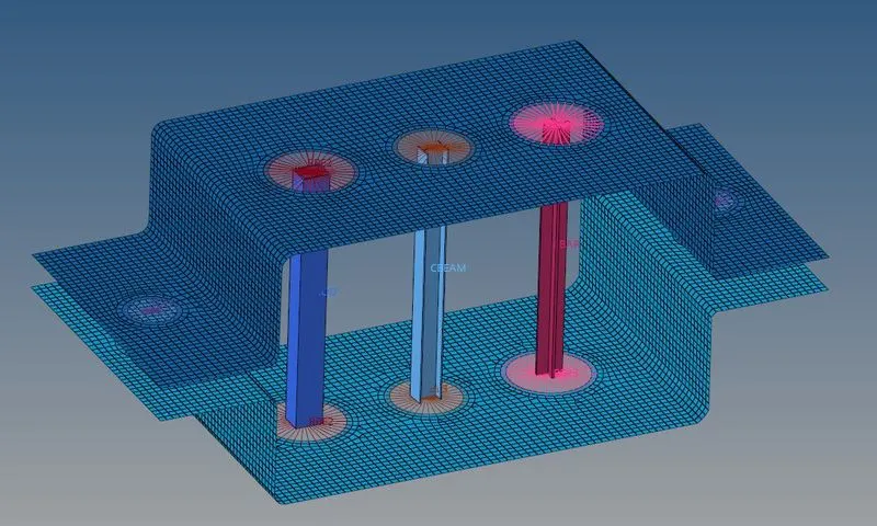
Figure 9: Rod, beam, and bar element with box cross-section, I-section, and CROSS cross-section respectively.
In table 1, it was said that on the side holes a mass of 10 magnitudes has to be placed. To do that, a ‘masses’ tool was selected in the 1d section, in which, a node was selected where a mass has to be applied, the mass magnitude was given as 10, and element type was selected as CMASS1. Fig. 10 shows the CMASS1 element placed on two side holes. A property card was created, in which, card image was selected as PMASS, the magnitude was provided as 10, and all this property card was assigned to the mass component.
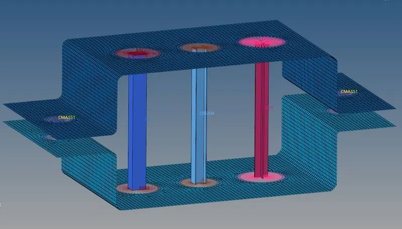
Figure 10: CMASS1 element placed on two side holes.
Now at the last, the two side holes had to be connected with their adjacent holes of other brackets using spring element. To deploy the spring element, in the 1d section the ‘springs’ tool is there. Using this tool, two center nodes of the hole was selected, an element type was selected as CELAS1. A property card was created, in which the card image was selected as PELAS, the material was assigned as steel, and this property card was assigned to the spring component. Figure. 11 shows the bracket with all the elements that were required.
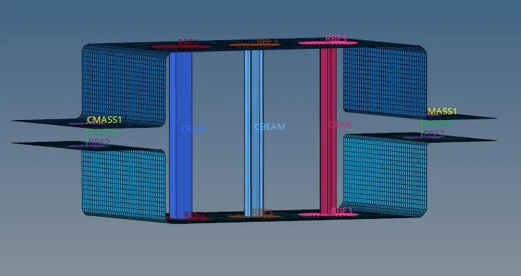
Figure 11: Bracket with all the required elements.
LEARNING OUTCOME
- After taking out the mid surface, it is better to create the material card, and the property card first, before, discretizing the model, and apply those material and property to the mid surface.
- The selection of elements depends on the type of solver.
- In case, it is unable to give all dofs to an element, create the element with some dofs and then update it with zero dofs.
RESULT
The bracket model was required to be discretized, and provide the 1d connectors. The model of the bracket when imported into Hypermesh, it was first made ready for taking out midsurface by deleting the solids. When the model was ready, the midsurface was taken out and discretized. With the given required data, the 1d elements were provided on each respective hole. RBE2, RBE3, bar, beam, rod (with different cross-section), spring, and mass element was used in the model.