Week 4- Challenge
Objective:
To mesh the given component and perform the following
Creat 1D elements on the following component with given cross-section and DOF
a. Rod element:- with only translational DOF and RBE2 link
Cross-Section: BOX- Dimension a= 12 mm
dimension b=10 mm
Thickness t= 0.75 mm
b. Beam element:- with all DOF and RBE3 link
Cross-Section: I Section- Dimension a= 8 mm
Dimension b= 10 mm
Dimension c= 8.5 mm
Thickness t1= 0.75 mm
Thickness t2= .6 mm
Thickness t3= .6 mm
c. Bar element:- with only x and y DOFs With RBE3 link
Cross-section: CROSS section- Dimension DIM1= 5 mm
Thickness DIM2= 1.2 mm
Dimension DIM3= 10 mm
Thickness DIM4= 1.2mm
d. & e. apply the mass of magnitude 10 with RBE2 link
f. Join the two components with Spring elements
Procedure:
1. Import the given model into hyperworks
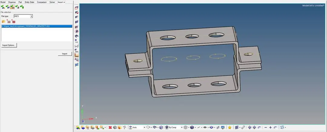
2. Hide the unnecessary wire frame component in the model and proceed to midsurface extraction.
3. Midsurafce can be extractred by selecting the midsurface option available in Geometry panel
Geometry panel `rarr`Midsurface `rarr`Auto extraction `rarr` Surface `rarr` Extract
`darr`
Extraction option `rarr` Skin offset
Here Skin offset extraction option is used because from trail and error this method is capturing the fillets perfectly.
4. After the midsurface are being created separately new material card is defined and separate property card is created for the midsurface created.
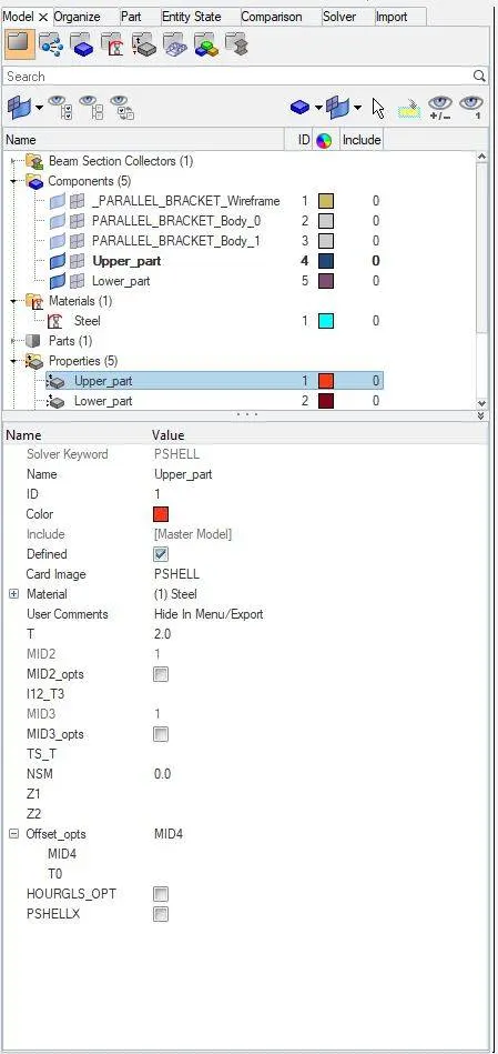
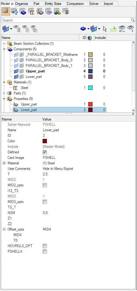
5. Now before proceeding to mesh, a washer surface needed to be created for the holes on the surface which can be created using quick edit option in Geometry panel.
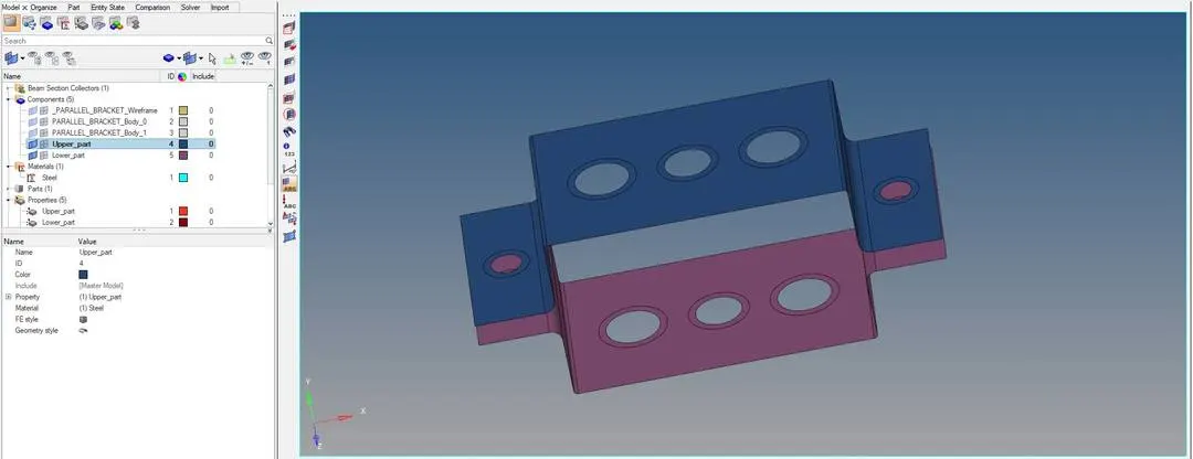
6. Now in 2D panel auto mesh option is selected to mesh the extracted midsurace.
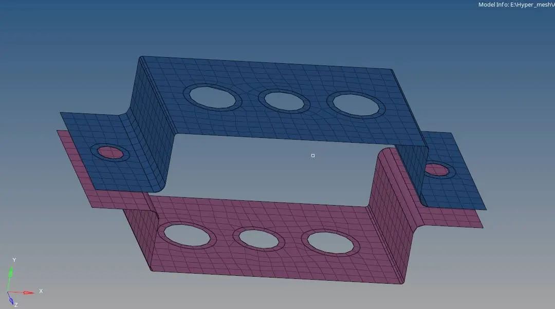
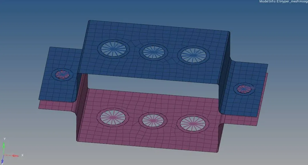
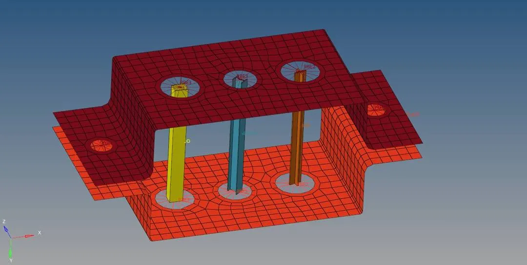
7. First we can create the rigids in all the holes, as named in the question hole "a" Nodes are selected to create a RBE2 With only translation DOF , For Hole "b" Nodes are selected to form RBE3 With all DOF and For hole "c" Nodes are selected to form RBE3 with only X and Y DOF. and for holes "d & e" RBE2 with a mass magnitude of 10 is created. similarly same operations are carried out on the bottom barcket as well as to create the rigids.
8. Now Hyperbeam option in 1D panel is opened to create a cross section of Rod, Beam and Bar element with the given dimension.
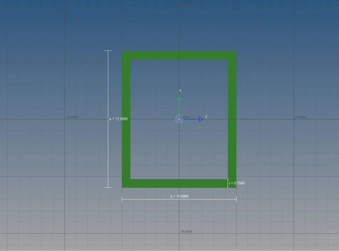
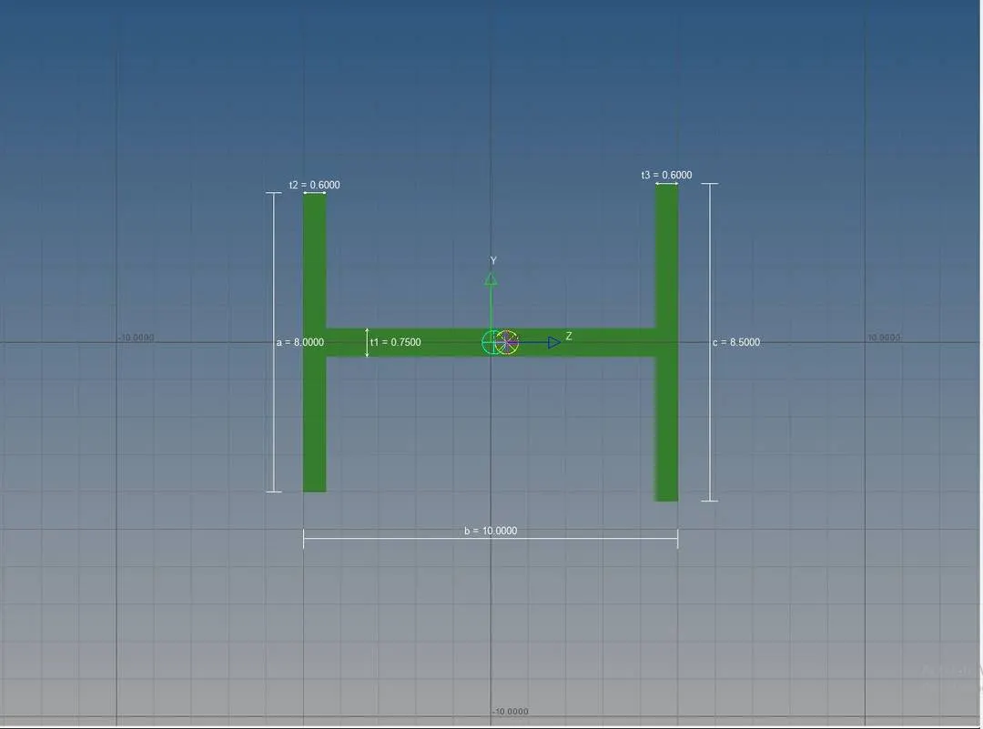
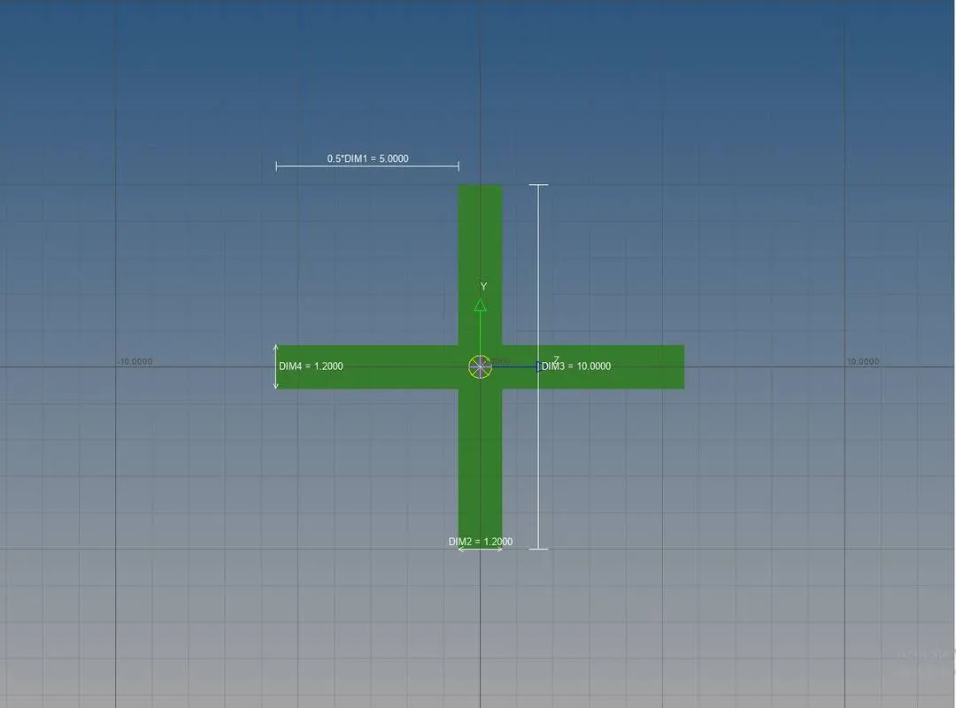
- With the center nodes from RBE2 created on hole "a" is selected a 1D element CROD is created by selecting rod option in 1D panel.
- With the center nodes from RBE3 created on hole "b" is selected a 1D element CBEAM is created by selecting the bar option in 1D panel.
- With the center nodes from RBE3 created on hole "c" is selected a 1D element CBAR is created by selecting the bar option in 1D panel.
- A node from both the bracket is selected from point "f" to create a spring element ( CELAS1) available in 1D panel.
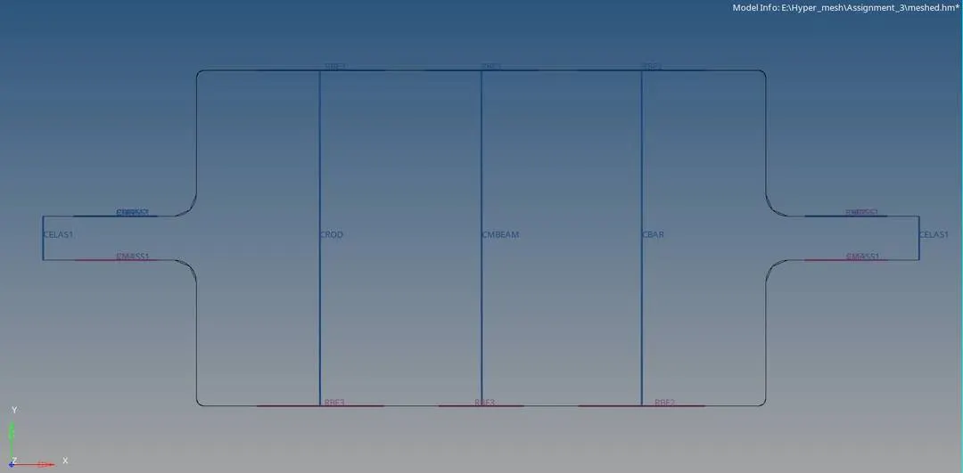
9. Now to assign property to the created 1D elements, three property card namely PROD, PBEAM and PBAR is created with beam section is selected from the cross section created earlier and it is updated to the 1D elements by using the update option availble in the bar and rod menu in the 1D panel.
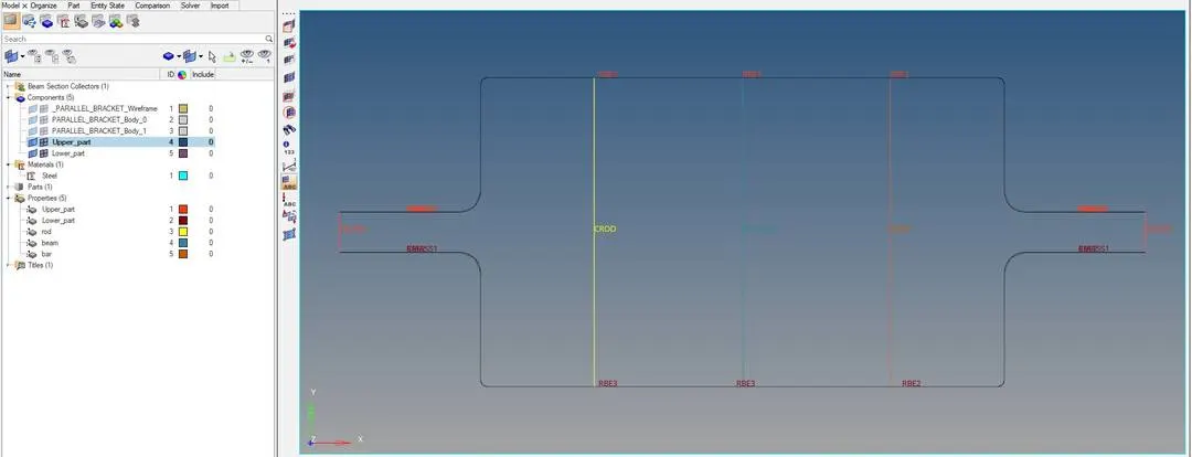
Final model Image: by property
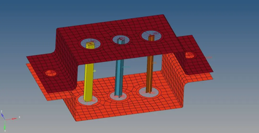
Final Model image: 1D detailed Element representation by property
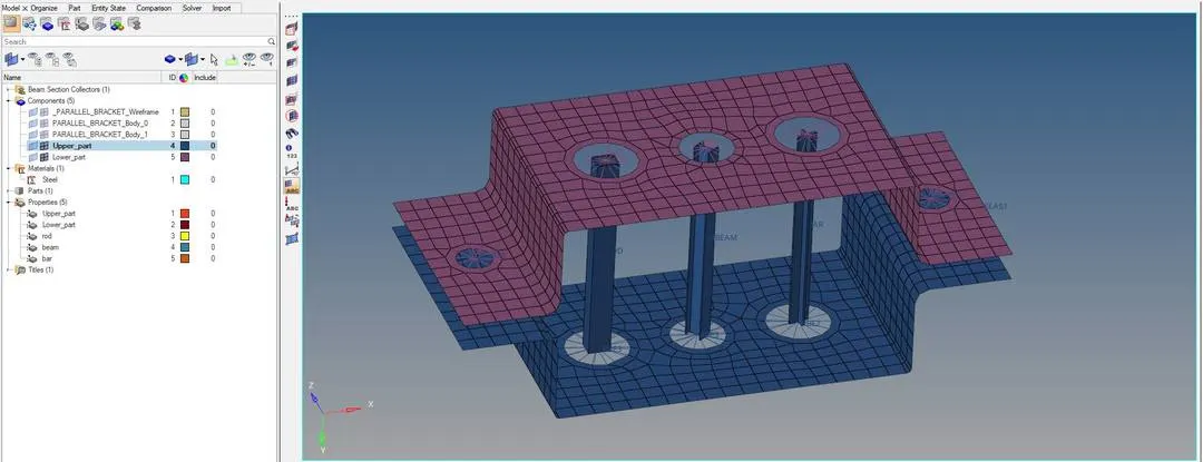
Final Model Image: by component
Conclusion:
- Understood the how to perform 2D mesh on a flat surface
- Understood various option in 1D panel and the creation and difference between RBE2 and RBE3 elements
- Understood how to create property, materials and cross section and to assign them to the surfaces.