Week 4- Challenge
Extraction of mid-surface, 2D meshing and generation of Bar, rod and beam elements using hypermesh
Aim :- To extract mid surface of given component, meshing it and generating bar, rod and beam 1 D elements at required areas with required cross section and DOF.
Problem statement :-
Creat 1D elements on the following component with given cross-section and DOF
a. Rod element:- with only translational DOF and RBE2 link
Cross-Section: BOX- Dimension a= 12 mm
dimension b=10 mm
Thickness t= 0.75 mm
b. Beam element:- with all DOF and RBE3 link
Cross-Section: I Section- Dimension a= 8 mm
Dimension b= 10 mm
Dimension c= 8.5 mm
Thickness t1= 0.75 mm
Thickness t2= .6 mm
Thickness t3= .6 mm
c. Bar element:- with only x and y DOFs With RBE3 link
Cross-section: CROSS section- Dimension DIM1= 5 mm
Thickness DIM2= 1.2 mm
Dimension DIM3= 10 mm
Thickness DIM4= 1.2mm
d. & e. apply the mass of magnitude 10 with RBE2 link
f. Join the two components with Spring elements
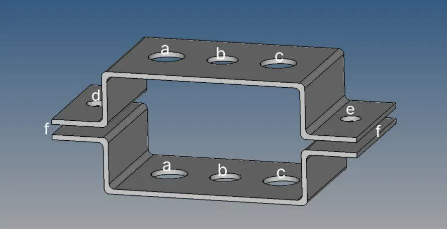
Software used :- Altair Hyperworks student liecenced version 2020
Methodology :-
- Import given model into hyperworks.
- Geometry cleanup
- Extract mid-surface from given geometry.
- Create material and properties assign to components.
- 2 D meshing over extracted mid surface
- Creating 1 D elements with given dimension and DOF and assigning property to each
Procedure :-
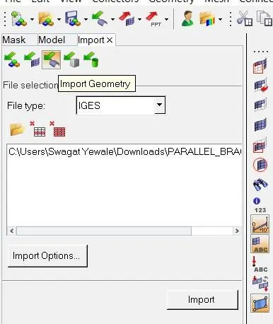
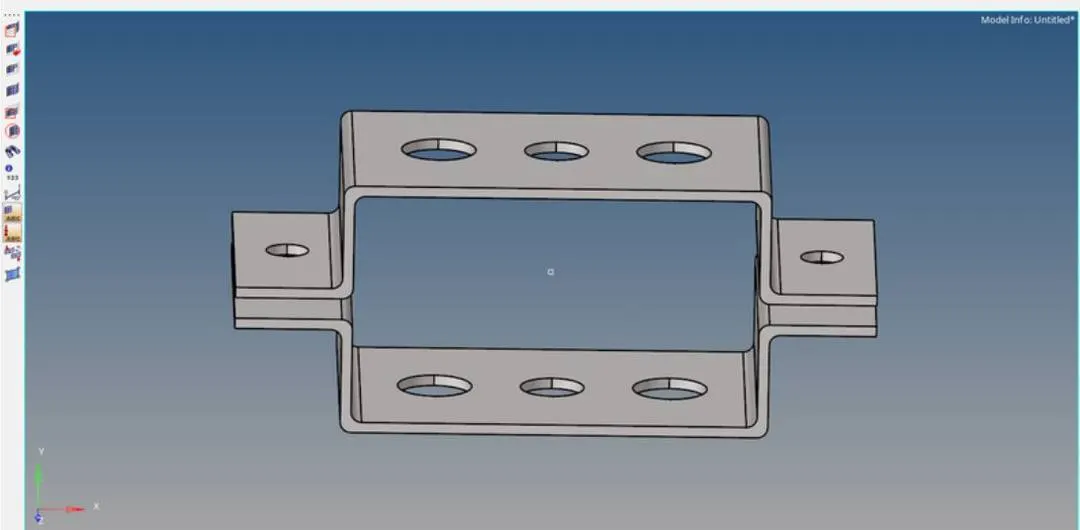
1. Import given model into hyperworks. :- First, we have to import geometry of model using Import model > Select IGES > Select file > Import option as shown in image below. After importing model into hyperworks press F key to fit model on screen.
2. Geometry cleanup :- After importing model we need to do geometry cleanup for that use Geometry > Auto clean-up > select all surfaces > auto cleanup option.

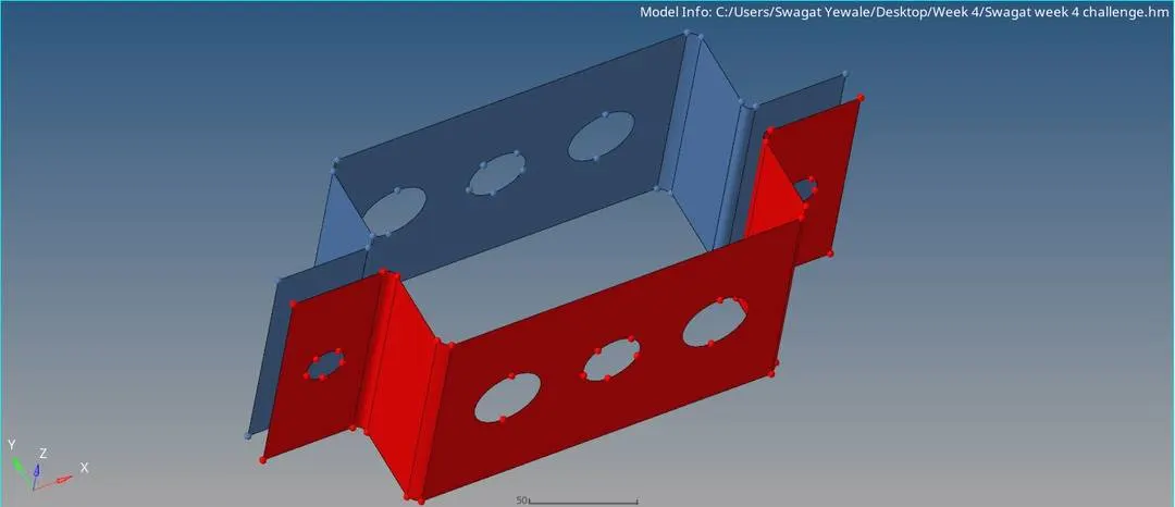
3. Extract mid-surface from given geometry. :- In geometry module mid-surface tools allows to find mid-surface from parent geometry as thickness of component is even so we can use auto midsurface option to create mid surface with default settings provided in it.

By using this option we can extract mid-surface as shown in below image. after generating mid-surface hide or delete parent geometry. Rename generated mid surface as per our convinient and also change the color of mid surfaces. Generated mid surfaces are shown below.
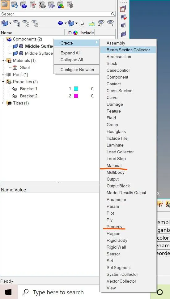
4. Create material and properties assign to components. :- For assigning properties and material we have to select model view window after that press right click and create properties and material as shown in image below. assign to the component 1 and 2.
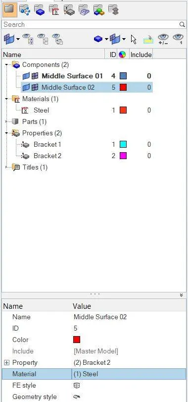
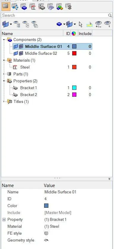
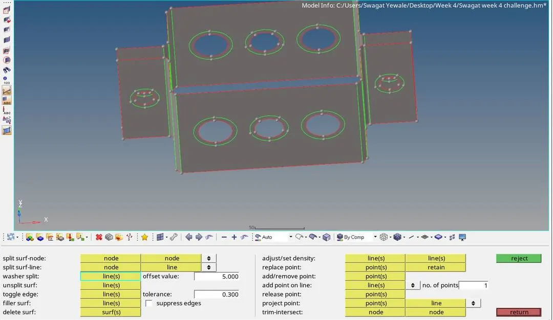
5. 2 D meshing over extracted mid surface :- Before meshing we have to create washer split for better mesh flow pattern and stress concentration is more in that area. washer split can be done by Geometry > Quick edit > washer split > Type value as 5 mm > Select hole one by one and washer split is generated as shown in image below.
After that we can move to 2D meshing by selecting 2D > Automesh > select surface need to be mesh > Enter element size as 5mm ( As a no element size and quality criteria given in problem statement so select suitable element size ) > select elemet type as mixed type > Mesh. The generated mesh and its steps is shown in fig below.

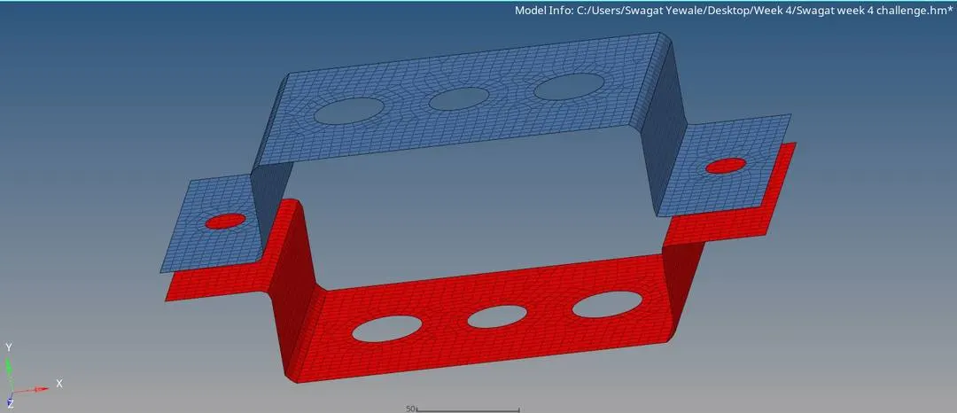
6. Creating 1 D elements with given dimensions and DOF and assigning property to each :-
1. Create rigids elements :- Here, we have to create two rigid RBE2 connections with only translational DOF for rod element at point a as given in problem statement so create RBE2 element by using 1D > rigids > create node > Select nodes by path > Unselect translational DOF which is dof1, dof2 and dof3 > create option as shown in image below
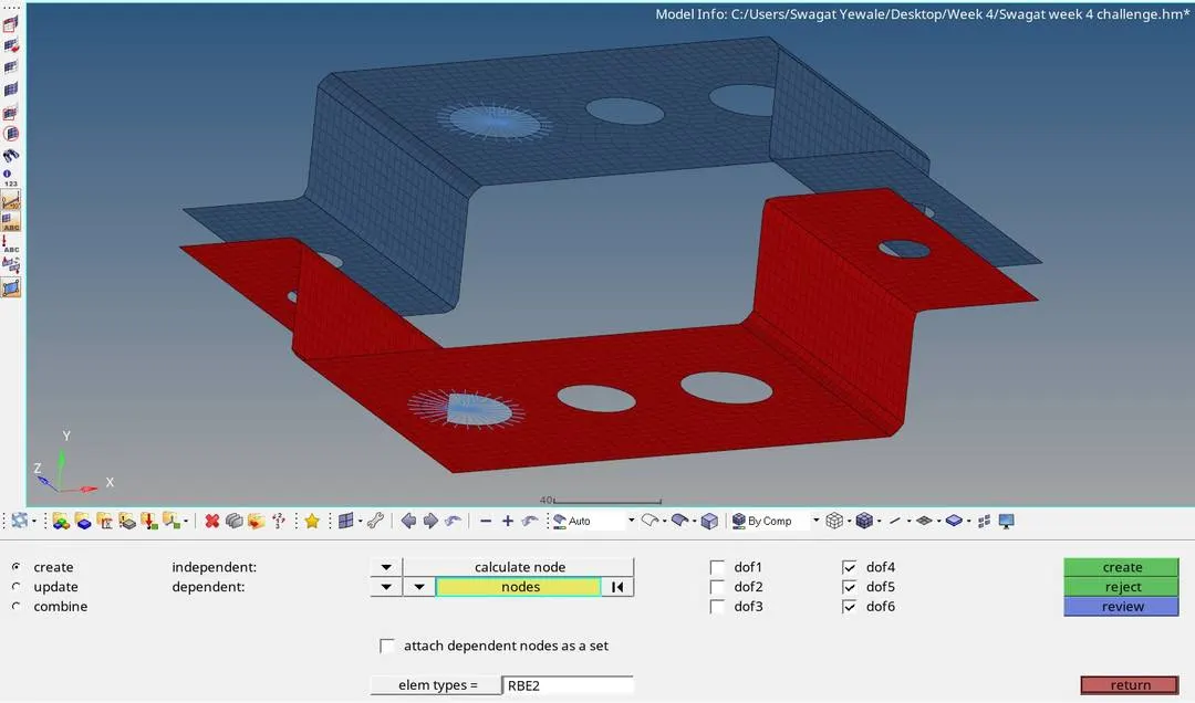
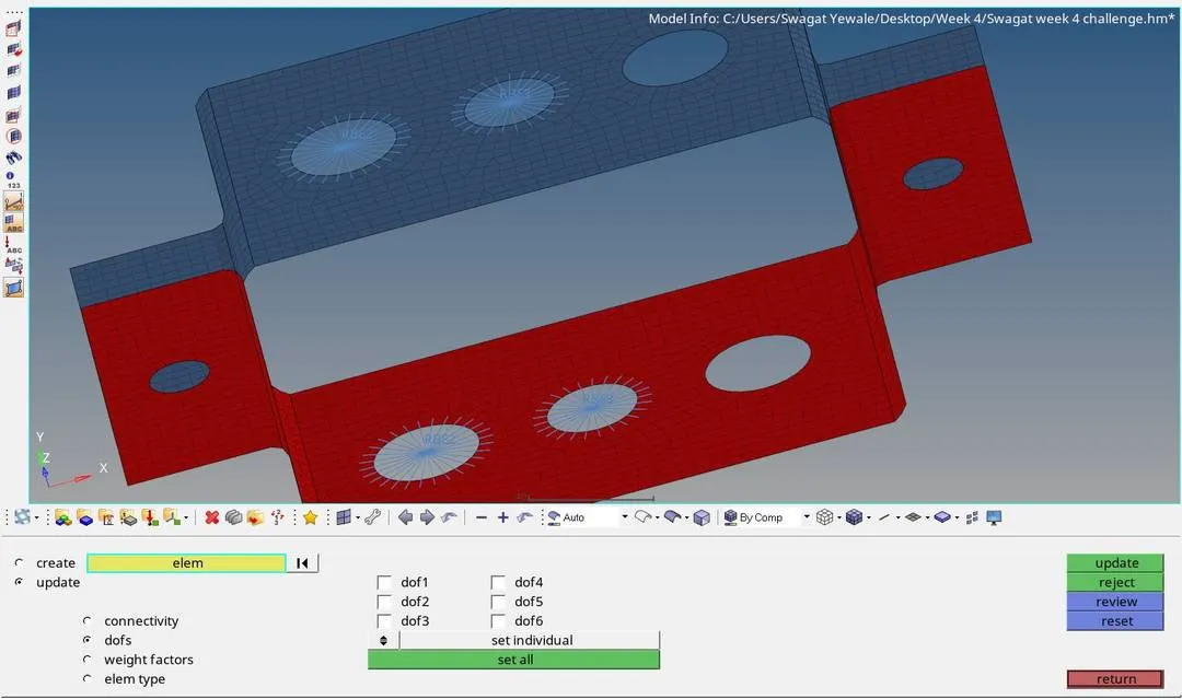
For beam element we have to create RBE3 elements with all DOF as given in problem statement so create RBE3 elements at B point by using 1D > RBE3 > select Nodes by path > unselect all dof > create option as shown in image below
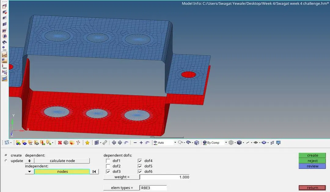
For bar element at point C we have to create RBE3 element with DOF in X and Y direction only by using 1D > RBE3 > select Nodes by path > unselect dof1 and dof2 > create option as shown in image below
2. Create Rod, beam and Bar section :-
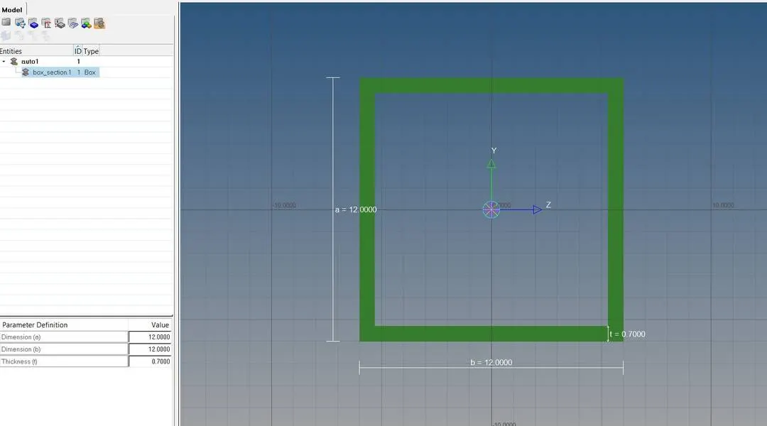
a. Rod element:- with only translational DOF and RBE2 link :- For creating rod select 1D > hyperbeam > standard selection > hyperbeam > thinwalled box > create option as shown in image below. After that type given dimensions for Cross-Section:
BOX- Dimension a= 12 mm dimension
b=10 mm Thickness t= 0.75 mm

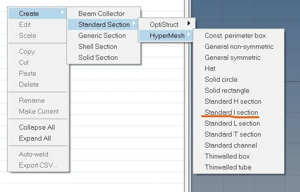
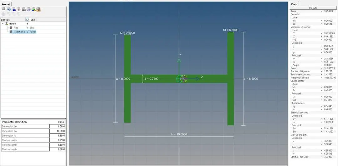
b. Beam element:- with all DOF and RBE3 link For creating beam section use following path right click in database window of hyperbeam view > create > standard section > Hypermesh > Standard I section and give proper dimensions as given in problem statement.
Cross-Section: I Section- Dimension a= 8 mm
Dimension b= 10 mm
Dimension c= 8.5 mm
Thickness t1= 0.75 mm
Thickness t2= .6 mm
Thickness t3= .6 mm
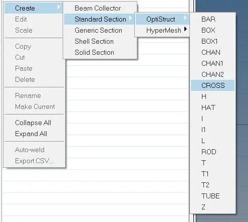
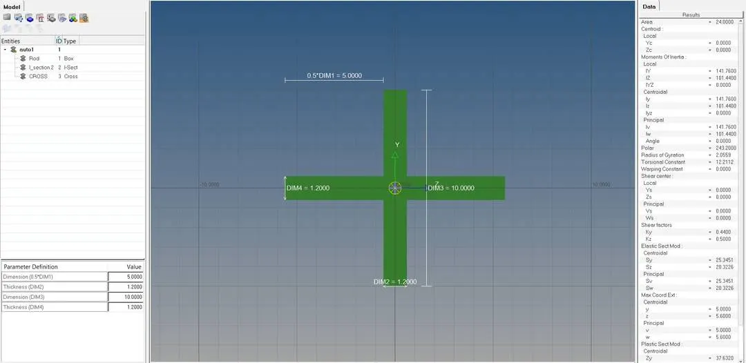
C. Bar element:- with only x and y DOFs With RBE3 link :- For creating bar section use following path right click in database window of hyperbeam view > create > standard section > optistruct > CROSS section and give proper dimensions as given in problem statement.
Cross-section: CROSS section- Dimension DIM1= 5 mm
Thickness DIM2= 1.2 mm
Dimension DIM3= 10 mm
Thickness DIM4= 1.2mm
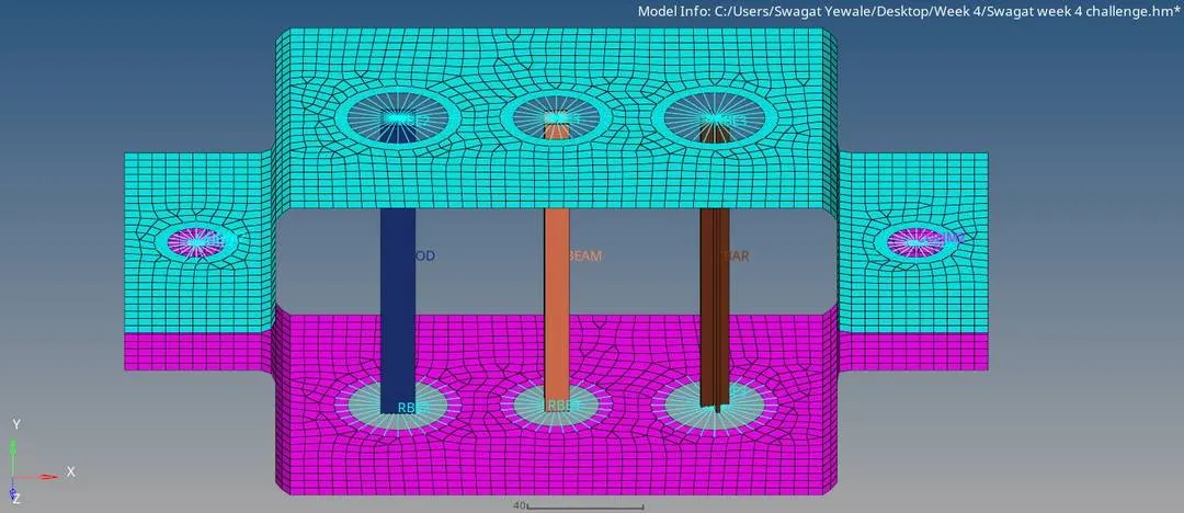
After creating cross section of rod, beam and bar assign it in actual model with help of 1D > Rod > create > select start node and end node > Assign property > Select element type as CROD it will create CROD element at a point. similarly create CBEAM
and CBAR element at points b and c respectively. below images shows that procedure for creating 1D element.



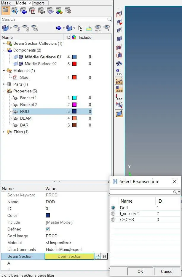
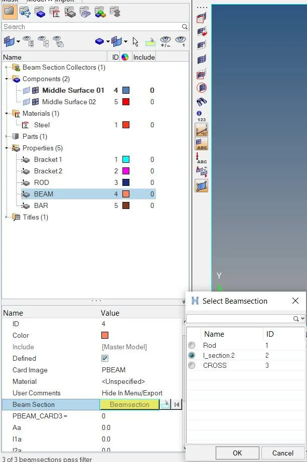
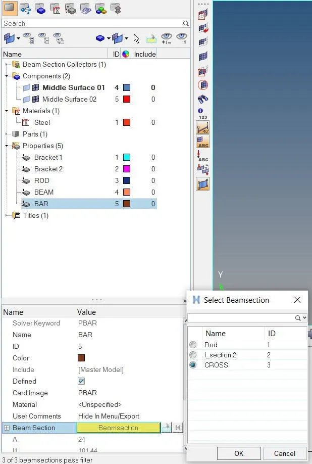
Create new properties for rod, beam and bar elements and assign card image and beam selection as per theire element type as shown in below images.
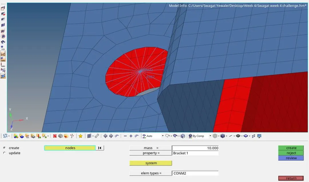
d & e. Application of masses at point d and e :- At point d and e we have to create rigid RBE2 element for showing mass with magnitude 10 as given in problem statement. For creating RBE2 element use 1D > Rigid > Select nodes with path > select all DOF > create option. after that use 1D > Masses > select node > enter mass value as 10 to apply masses.
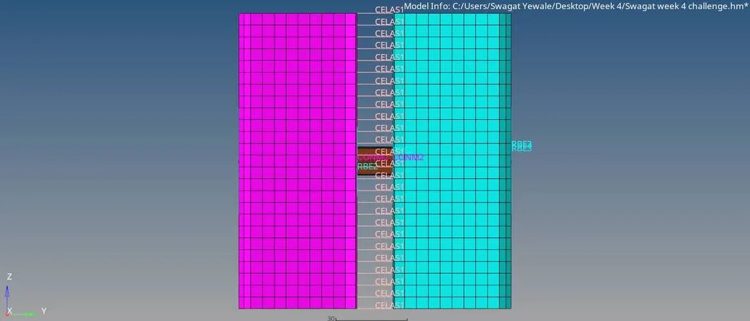
f. Join the two components with Spring elements :- To join two componenets with spring element at points f use following path 1D > Springs > select first node > select second node it will directly create spring element.
Final model image :-
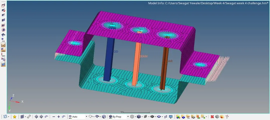
Conclusion :- Hence, we have extracted mid-surface properly, 2D meshed both brackets and created 1D elements with given cross section dimensions and degree of freedom.