Week 4 Challenge
- Create a terrain model by different methods –
- By Graphical Filter
- By text interpolation
- By elements
METHOD -1
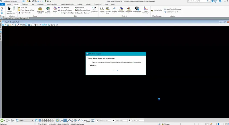
By Graphical Filter :Step 1: Opening File
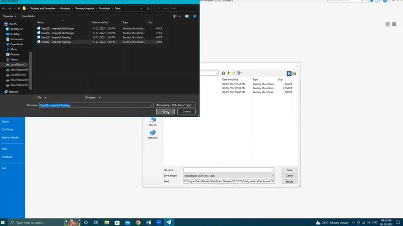
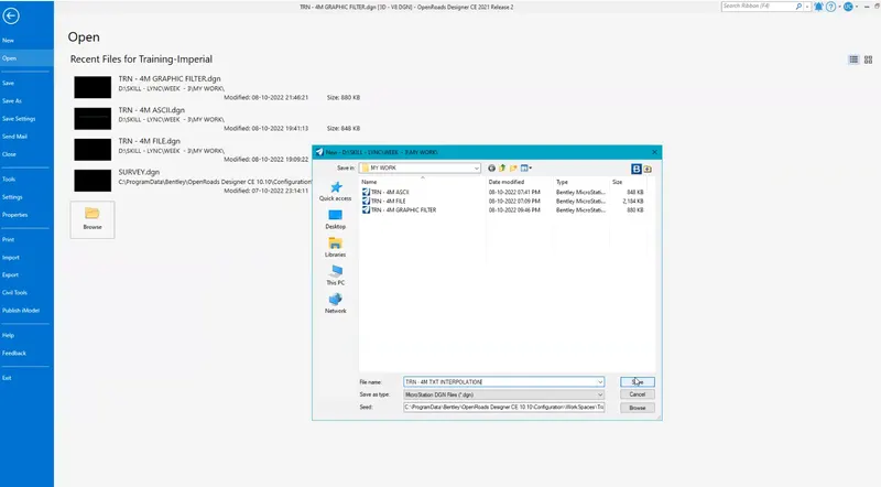
Open a New file with a 3D seed file - Set name as Terrain by Graphical filter and click save to open file
Step 2: Attaching Survey data
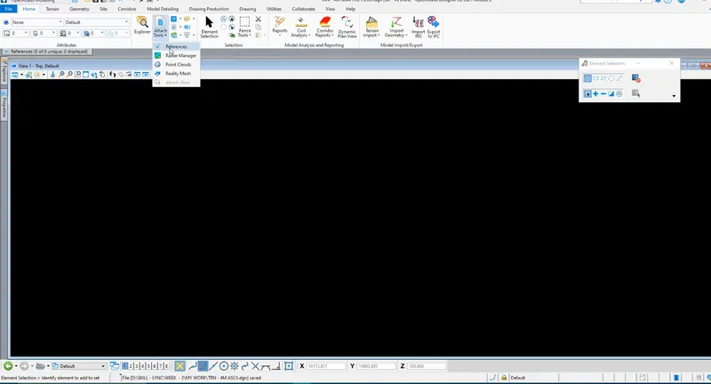
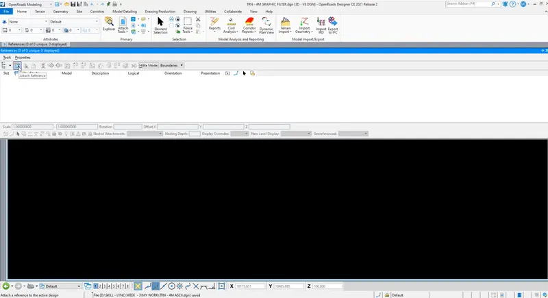
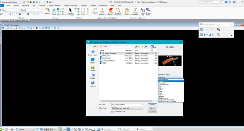
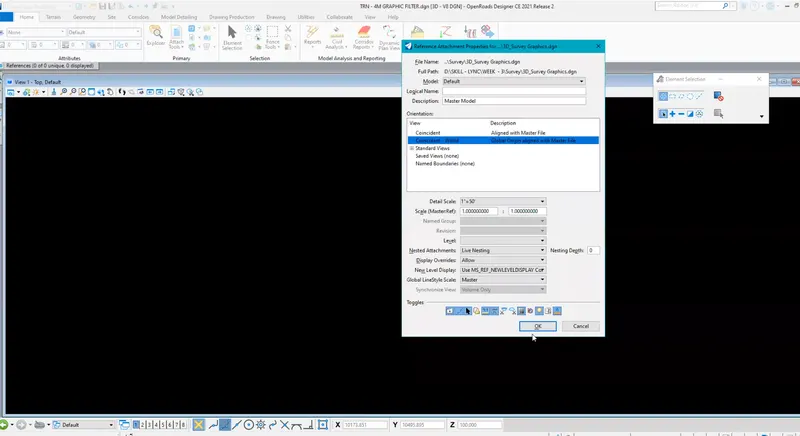
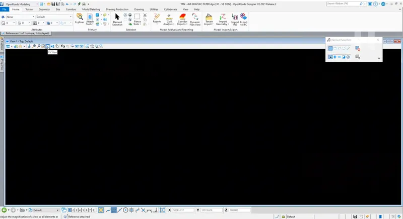
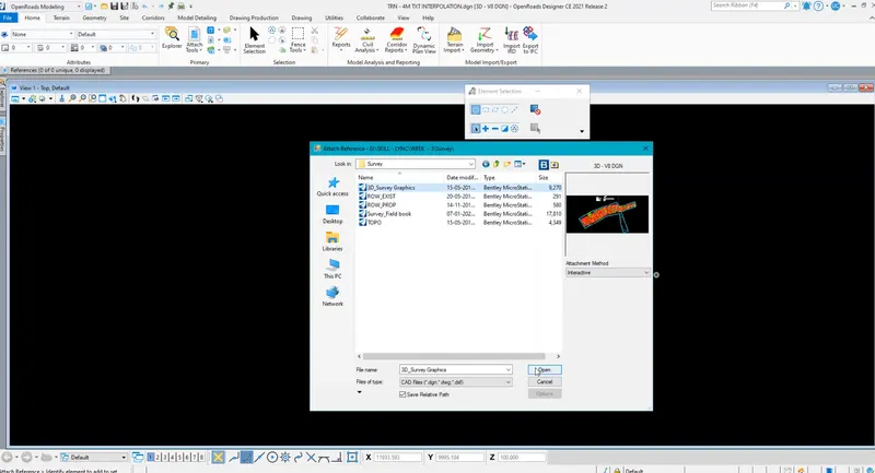
In-Home tab click on Attach tools and click on references - Click on Attach and select '3D_Survey Graphics file - Set attachment method as interactive - Click open - Click ok and click fit view to view the file
Step 3: Using Graphical Filter
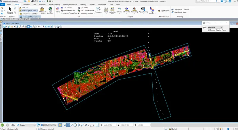
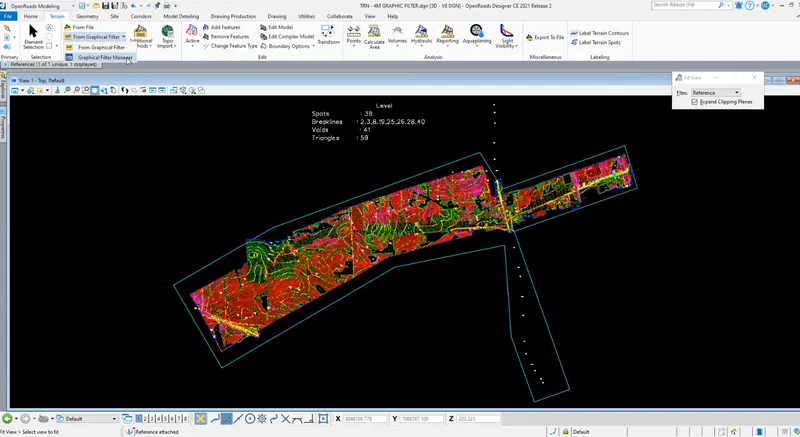
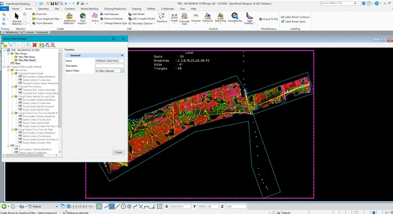
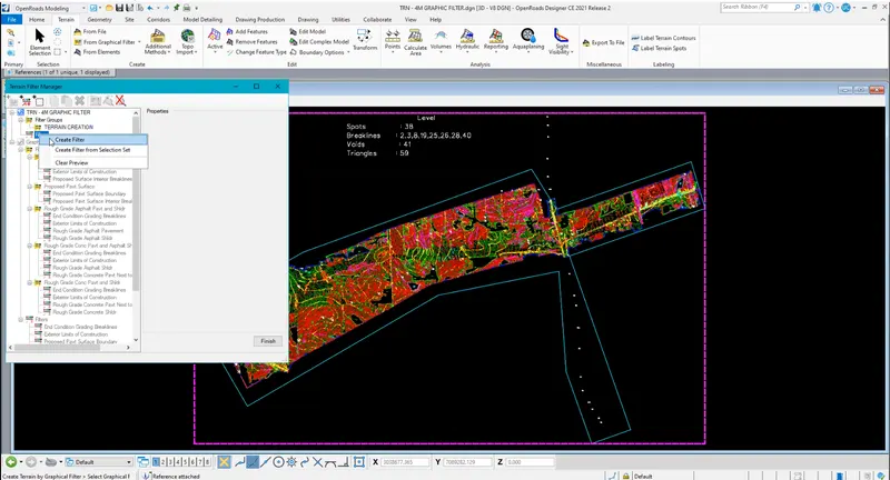
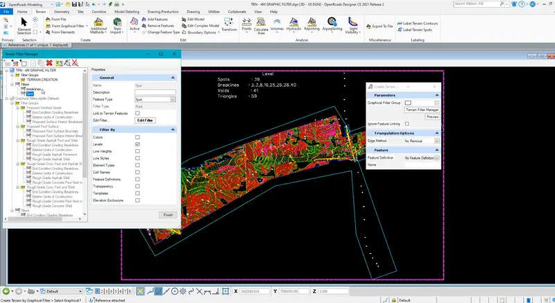
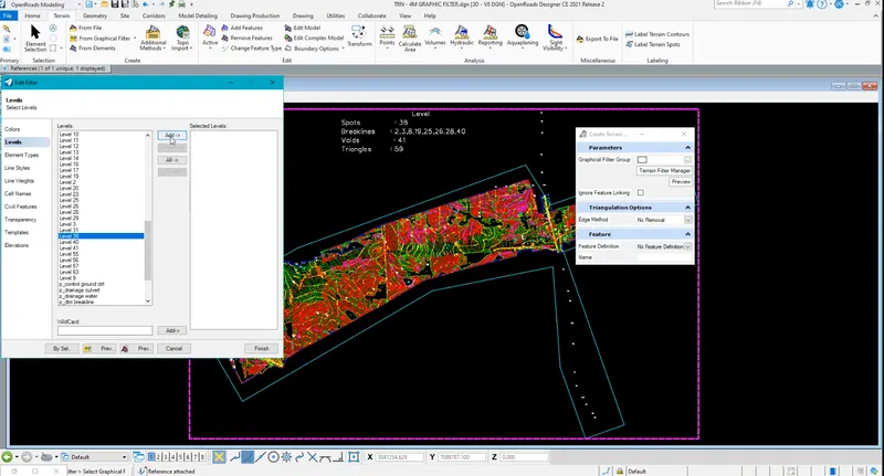
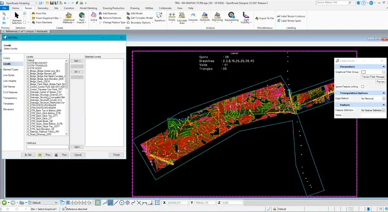
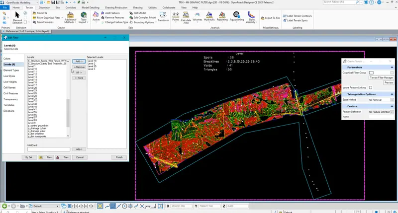
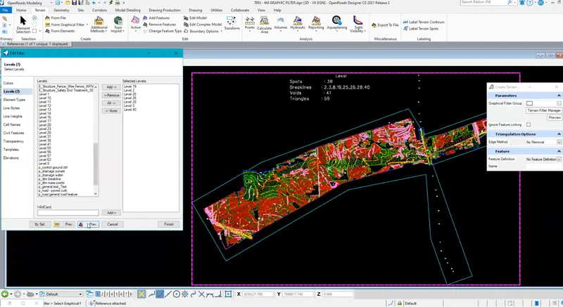
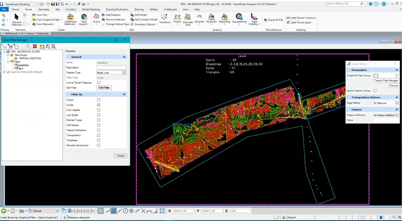
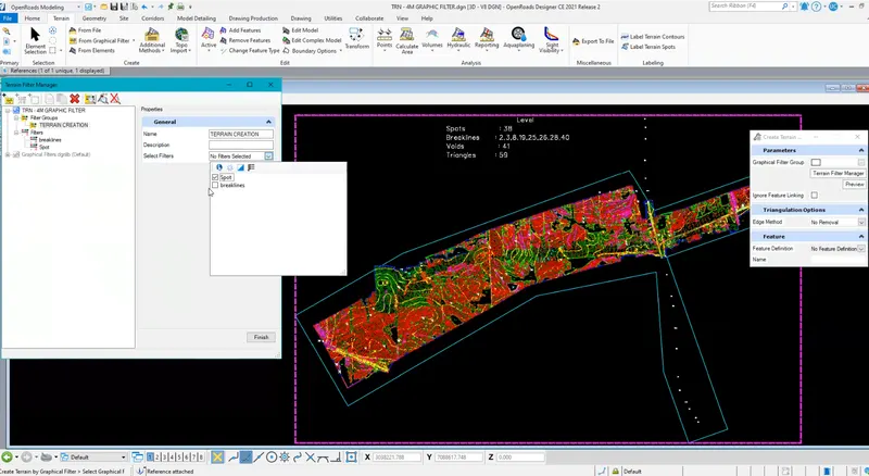
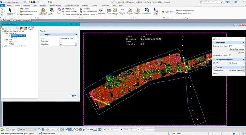
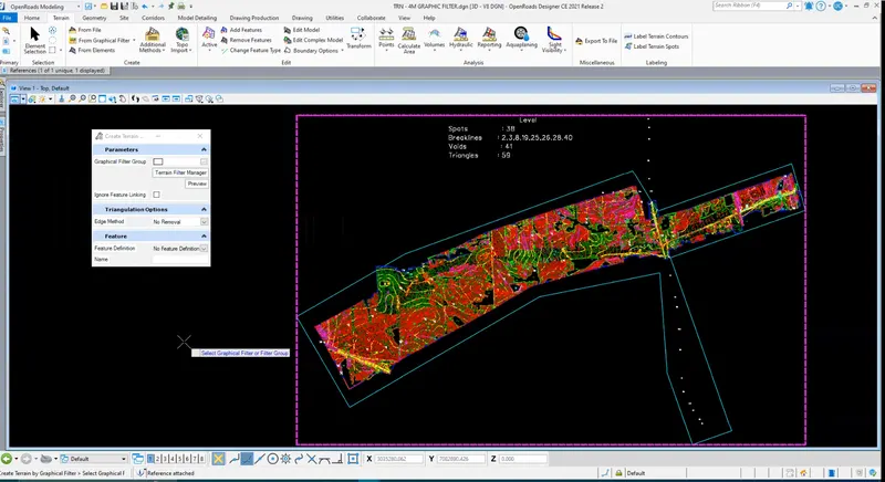
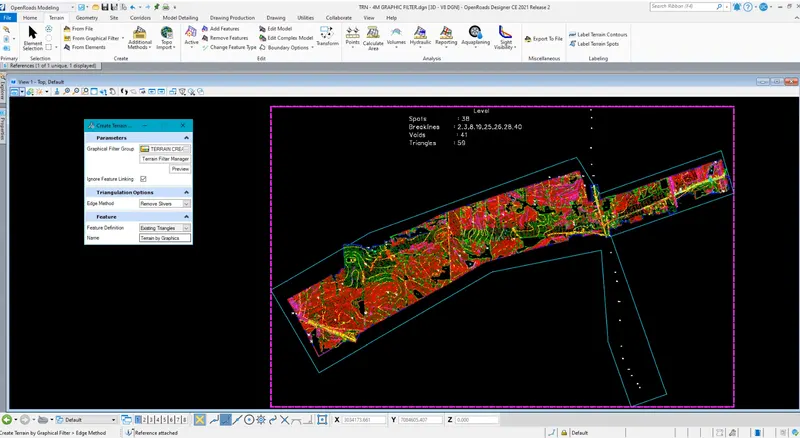
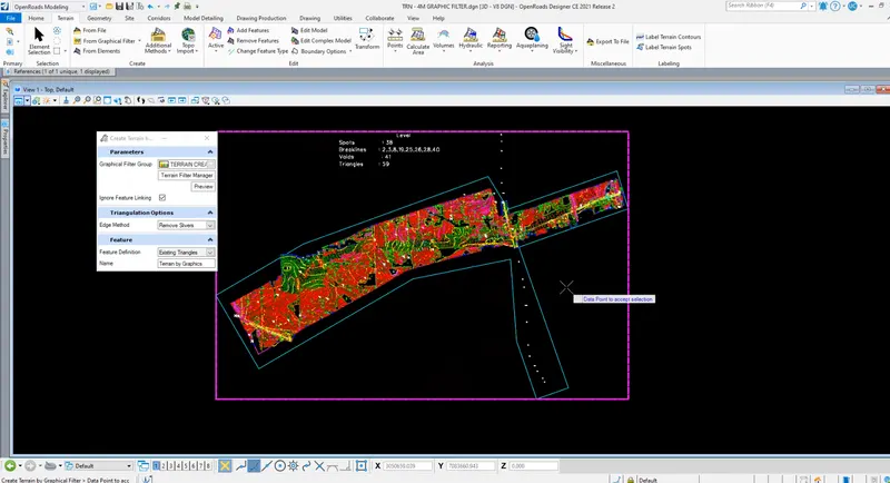
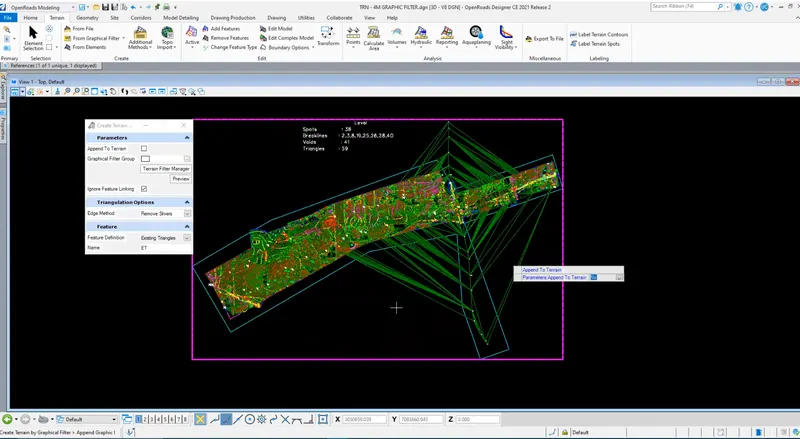
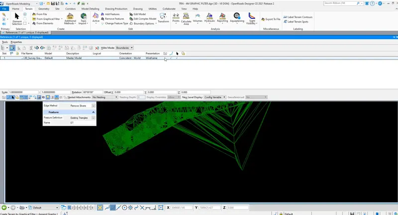
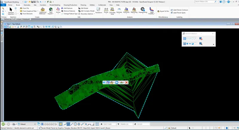
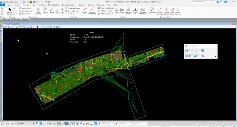
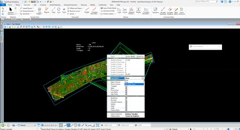
Go to the Terrain tab and click on From graphical filter - Click on Terrain Filter manager - Add New filter groups and filters as follows - Name filters as Spots and brake lines - Set Feature according and add levels of spots and Levels accordingly as follows - Click finish - Add spots filter to the terrain filter group - Click finish - go to Graphical filter - Select the filter group created - Set Edge method as 'Remove Slivers" – Set Feature Definition as Existing triangles.

METHOD -2
By Text interpolation: Step 1: Opening File
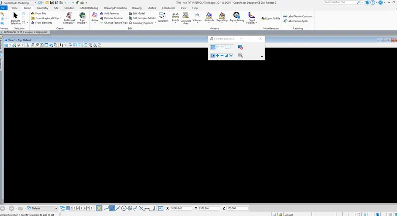
Open a New file with a 3D seed file - Set name as Terrain by text interpolation and click save to open file
Step 2: Attaching Survey data
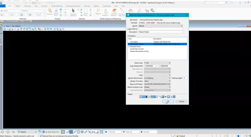
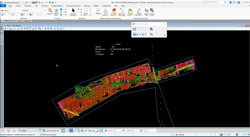
In-Home tab click on Attach tools and click on references - Click on Attach and select '3D_Survey Graphics file - Set attachment method as interactive -Click open - Click ok and click fit view to view the file
Step 3: Creating terrain
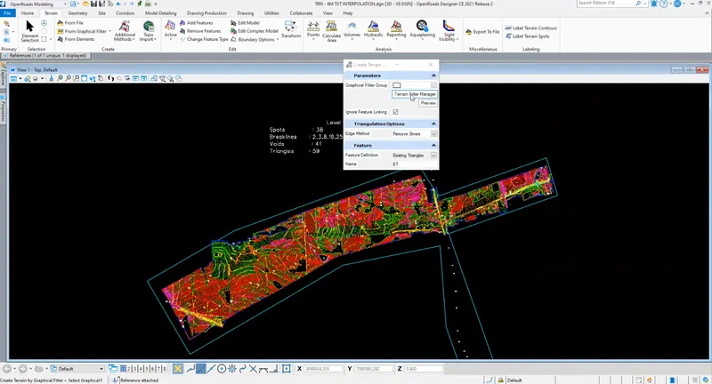
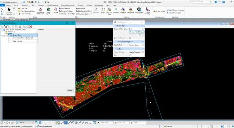
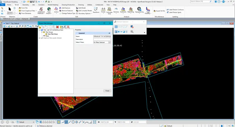
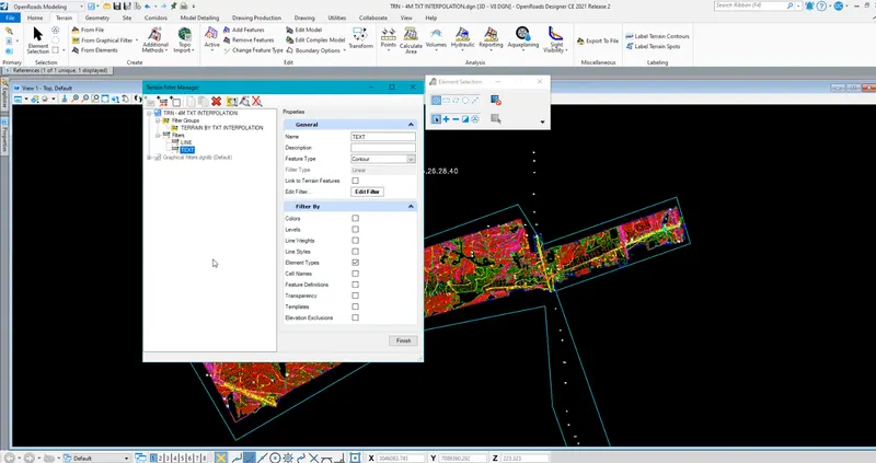
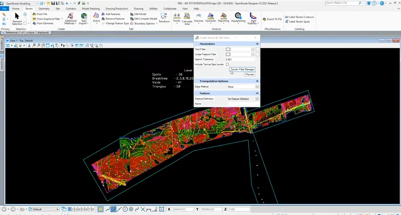
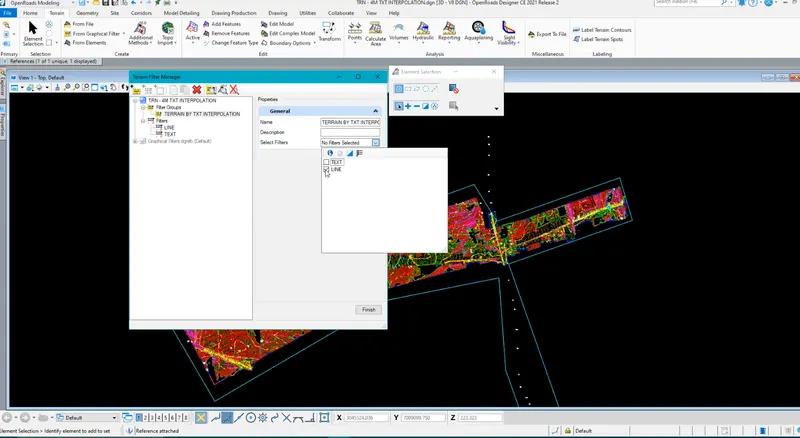
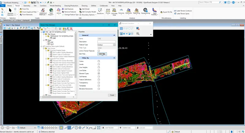
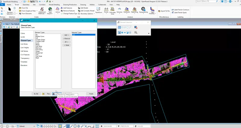
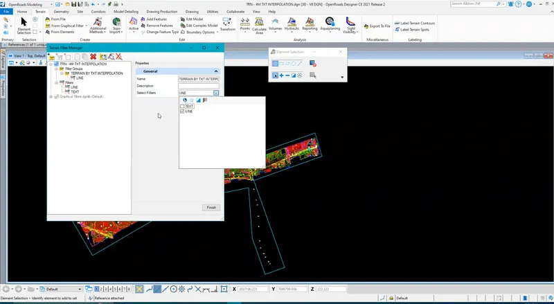
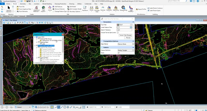
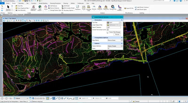
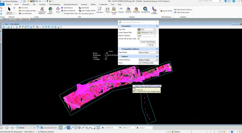
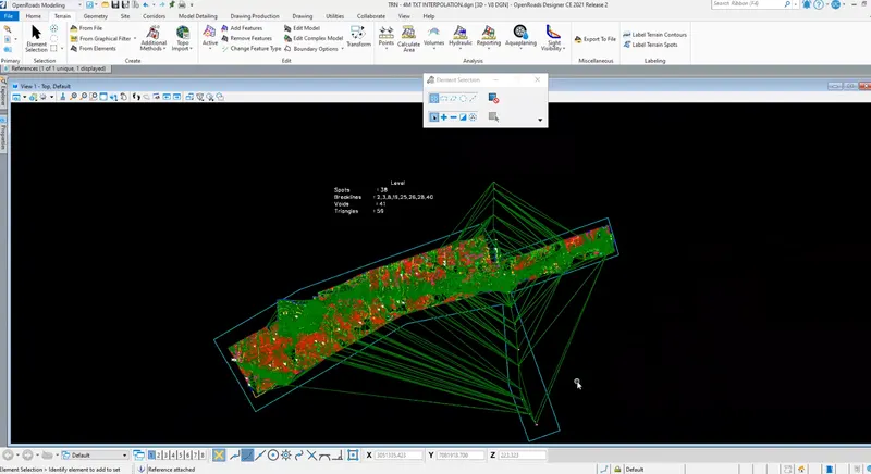
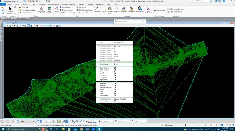
Go to the Terrain tab and click on Terrain by Additional Method - In that click Create Terrain model by Text interpolation - Click on Terrain Filter Manager - Create Text Filter using elements type as text - Create Lines filter using element type line string - Create filter group using only Lines filter created above - Set all the parameters in the popup box - Set edge method as Remove Slivers - Feature definition as Existing Triangles - Left-click to complete the process.
METHOD -3
From Elements
Step 1: Opening File
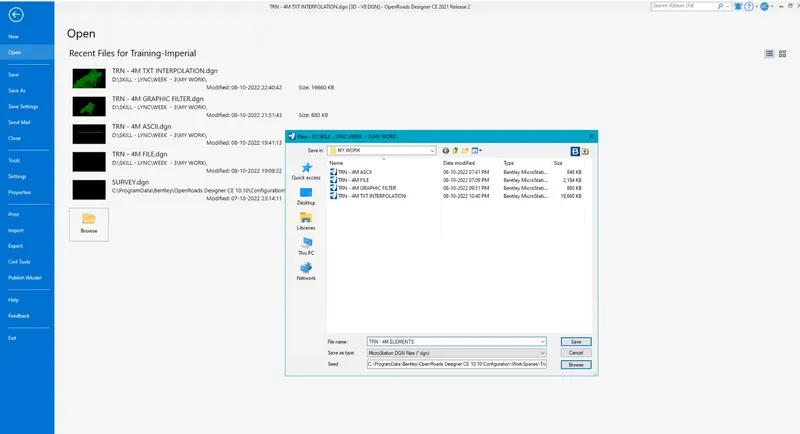
Open a New file with a 3D seed file - Set name as Terrain from elements and click save to open file
Step 2: Attaching Survey data
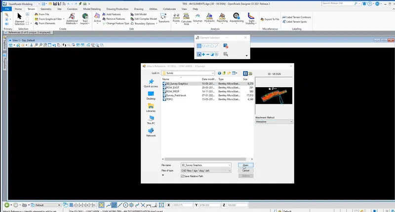
In-Home tab click on Attach tools and click on references – Click on Attach and select '3D_Survey Graphics file - Set attachment method as interactive - Click open - Click ok and click fit view to view the file
Step 3: Terrain from elements
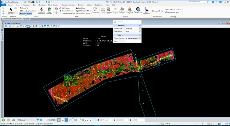
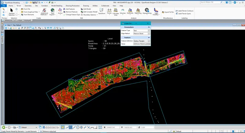
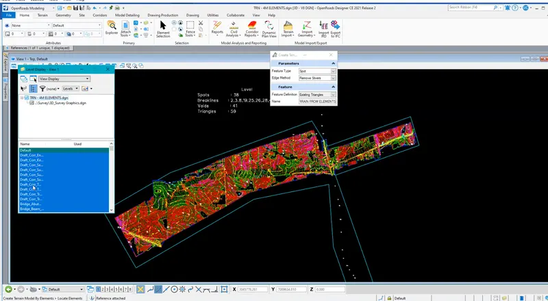
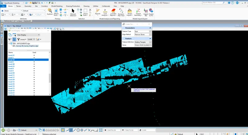
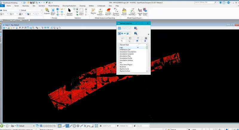
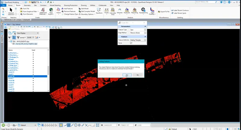
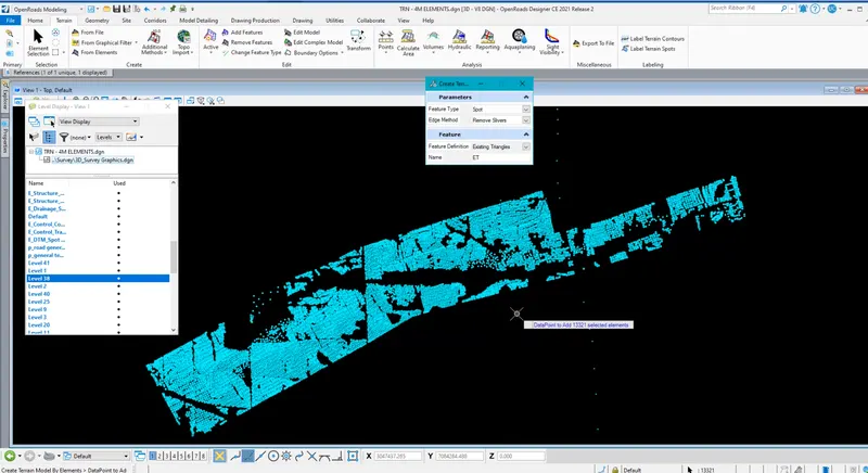
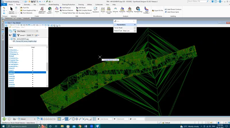
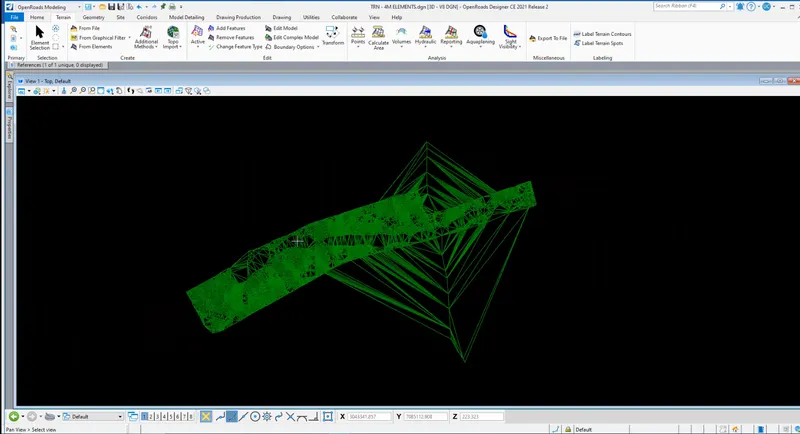
Click on Terrain From Elements - Set feature type as Spot - Set edge method as remove slivers - Feature Definition as Existing Triangles - Go to the Home tab and click o Level display - Click on the reference file - Do Right-click and click on "ALL OFF" - Select Layer 38 which is spots - Go to Element selection by layer and click on Line to select all spots - We can see 13231 spots got selected - Right-click to reset -The resulting Triangles appeared as below.
2.Edit the terrain model created
Aim: Edit the terrain model
Procedure:
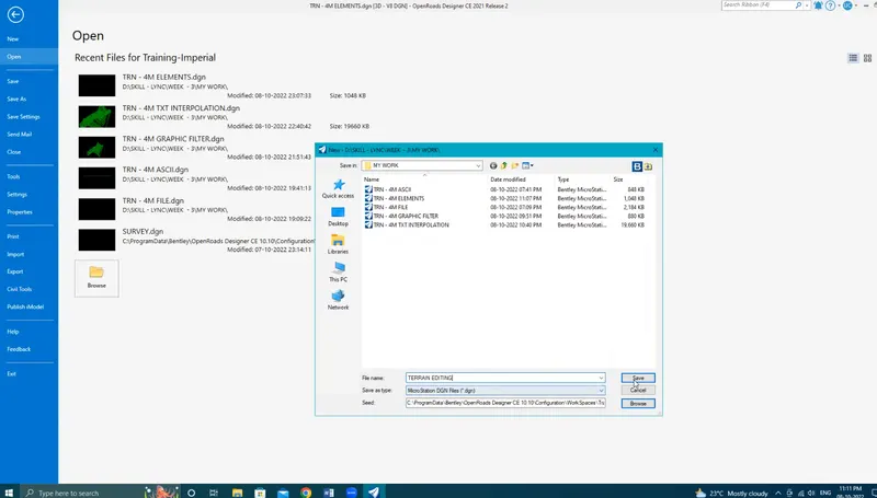
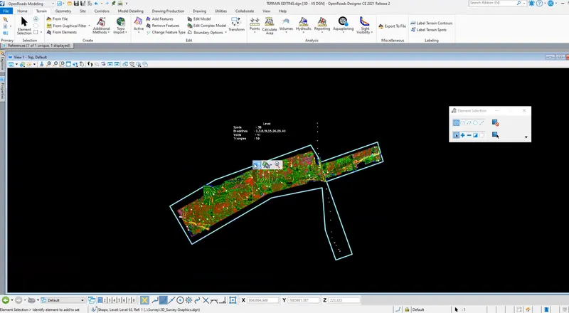
Step 1: Open Terrain Model -Create a new dgn file using the '3D seed imperial' seed file - Set name as terrain editing - Open the terrain from graphics elements created earlier - Click open and click fit view - Set overrides as yes.
Step 2: Editing Terrain Model
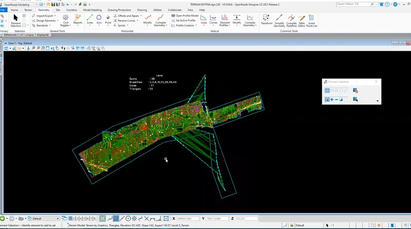
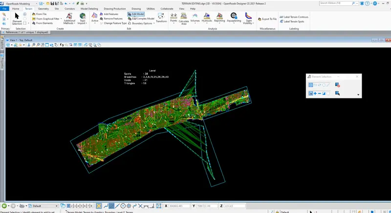
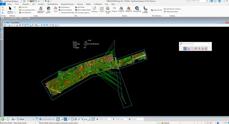
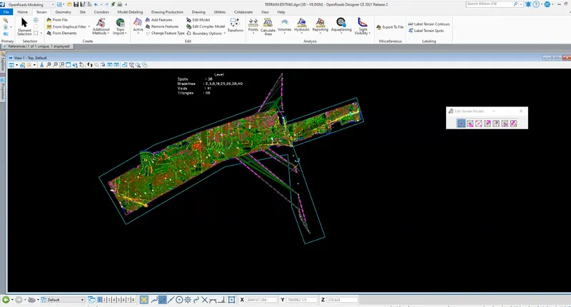
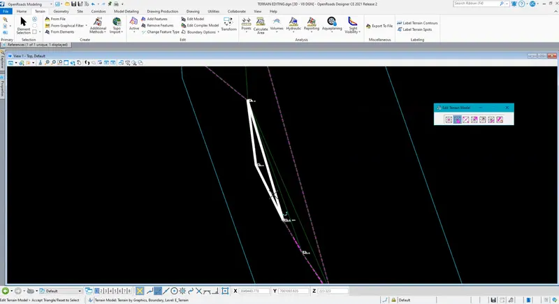
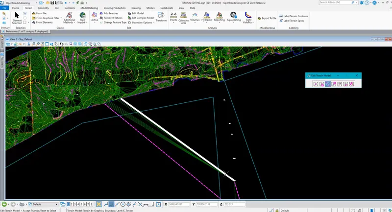
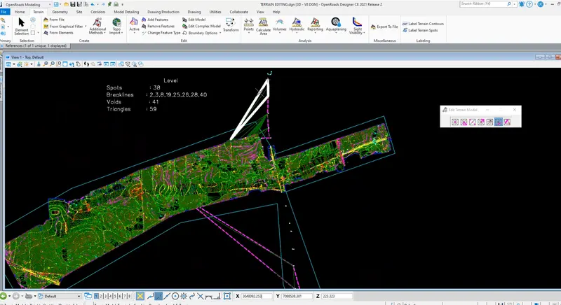
Go to the Terrain tab click on edit terrain - Use various options and delete unwanted spots and triangle
- Remove spot – Place the cursor on the spot until a white spot is visible and click to delete
- Delete Edge triangles - Place the cursor on the unwanted edge triangle to delete.
- Swap triangle side - Select the triangle side to swap
- Add Vertex - Place the cursor on the area where a new vertex is needed and select the spot
- Move Vertex can be used to move the vertex
- Delete triangle line is used to delete the unwanted lines of terrain created using a line drawn a specific direction
3. Annotate the contours with labels
Aim: Annotate the contours with labels
Procedure:
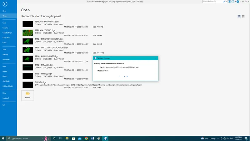
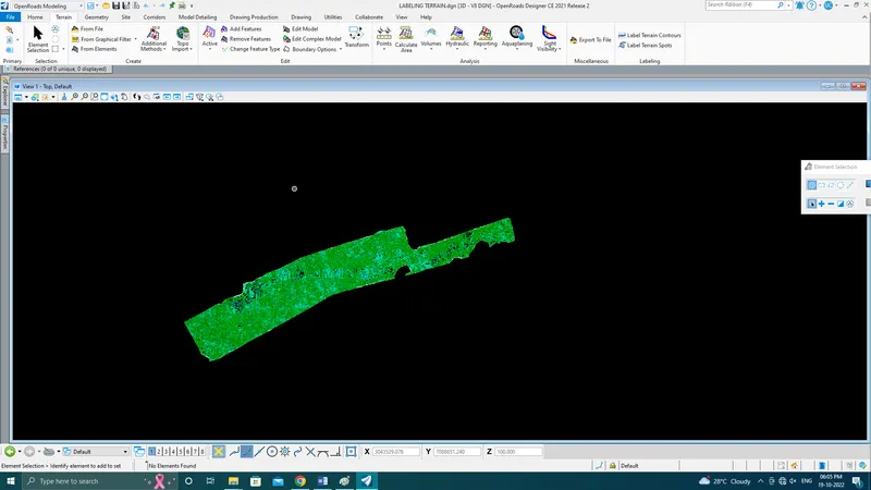
Step 1: Open Terrain Model
Step 2: Labelling Contours
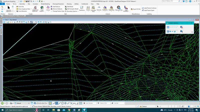
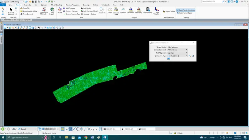
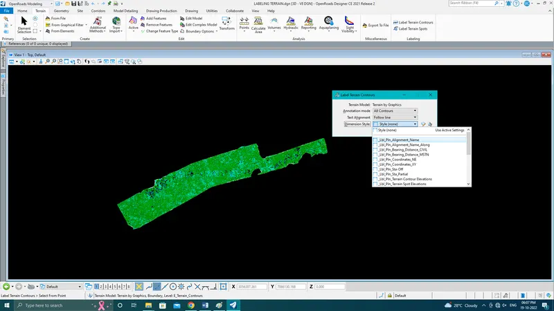
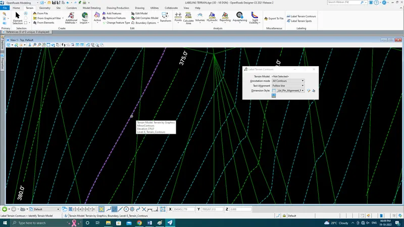
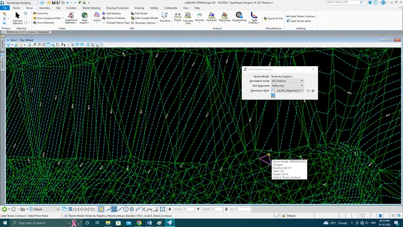
Go to the terrain tab and click on Labelling terrain Contours - Set the following settings - Select the terrain model - Annotation mode as All Contours - Text Alignment as Follow Line - Style as "Label Pin Alignment Name" - Zoom in the terrain view and label the contour
4.Change the contour interval.
Aim: change the contour interval
Procedure:
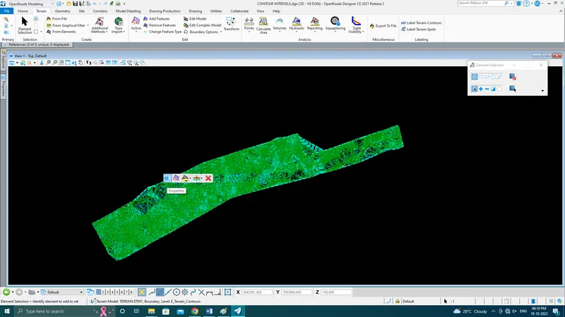
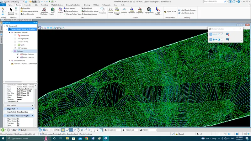
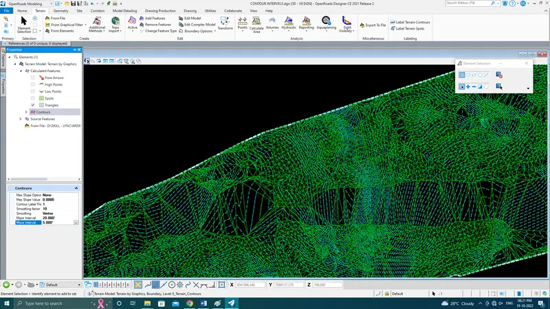
Step 1: Open Terrain Model
Step 2: Change Contour interval - Click the terrain model and hover to view properties of the terrain - Click on properties - Click on Terrain ET - Select the Calculated Features - Click on contours - Change the contour Intervals major as 20' and minor as 5'.