Mid-surfacing, Meshing with 1D Connections on a Mechanical Bracket using Hypermesh
Week 4 Challenge
- Aim: To understand the procedure of mid surfacing and creating various 1D Elements such as Rod, Bar and Beam. We understood the theoretical difference between the two Rigid Body Elements (RBE2 and RBE3) and even the procedure of how to apply them with different Degrees of Freedom.
- Procedure: 1. The very first step when we receive the model is to take the mid surface of it. To perform this operation we can use the Mid-surfacing option under the Geometry Option tab.

Mid-Surfacing Command
The main purpose of Mid-surfacing is to reduce the number of nodes and hence the number of equations which will further reduce the computing time and the storage space for the same model. After taking a mid-surface of the two brackets, we assign each mid surface a different property and give the thickness as an input.
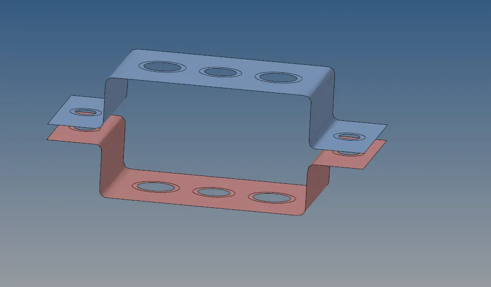
Mid surface of the two brackets with Split washers
2. After the Midsurface is taken we will mesh the given component. To mesh the component we will use the Automesh option under the 2D tab.

Auto-Mesh command
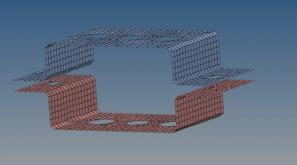
Meshed Component
The neccesary inputs such as the Mesh paramters and the Quality criteria is given. The Average size of the element is taken as 8 and the minimum and maximum element sizes are also set. The type of elements is kept as mixed and the mid surface is meshed accordingly.
3. Since after doing the mesh, the material is added in the properties tab as well. We understand that the Card image is specified by the Manufacturer and is to be given as an input by the person working on the model.
4. After the Meshing is completed, we will now add certain Rigid Body Elements (RBE) to various parts in the model. To Add an RBE 2 to the model, we need to use the Rigid command under the 1D Tab.

RBE 2 Command
We can adjust the Degrees of Freedom according to requirement.
5. Similarly we can create an RBE 3 Element as well. To create an RBE 3 element, we use the RBE 3 command under the 1D Tab. We select the nodes with which we want to use the RBE3 element and then create it as needed.

RBE3 Command
6. After the creation of RBE2 and RBE 3 elements, we will create the necessary Hyperbeam entities according to the given dimensions and the appropriate Cross section. We created different Cross section with different dimensions as given in the challenge.
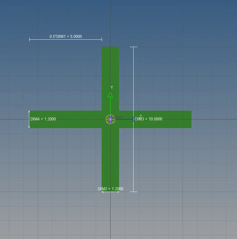
Bar
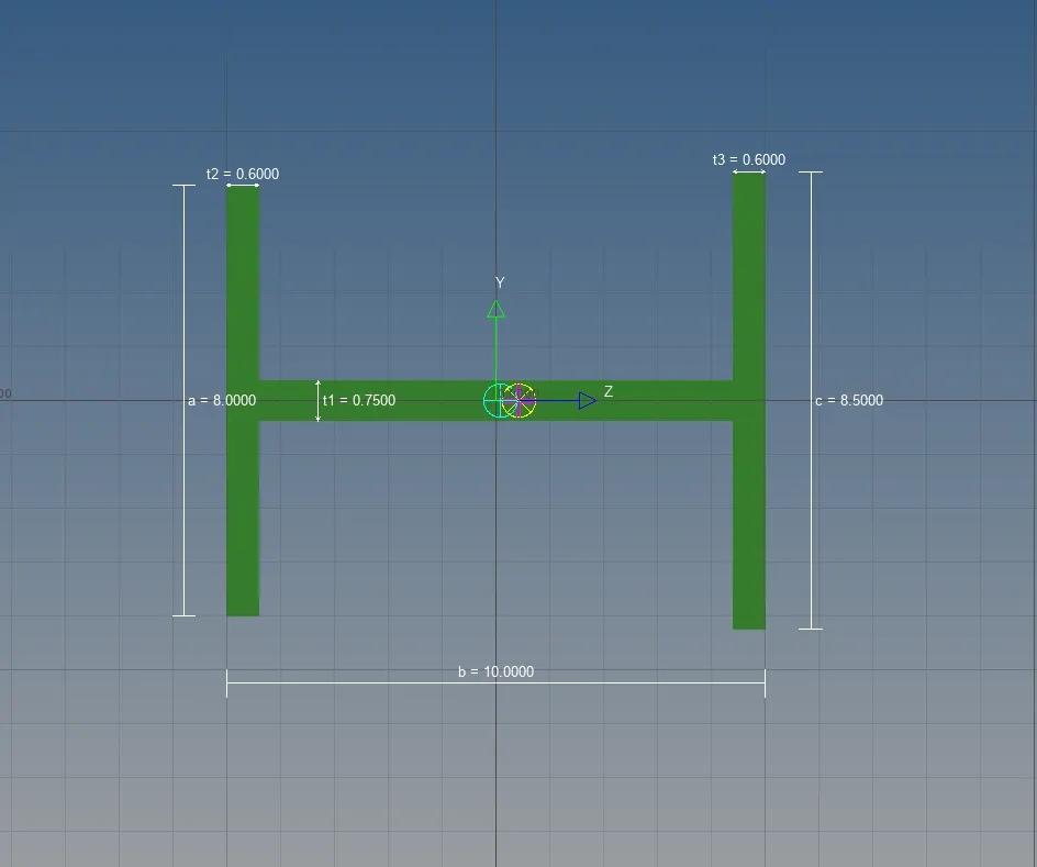
Beam
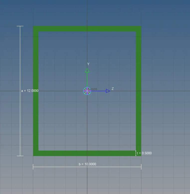
Rod
7. Now, we need to create seperate properties for each and every Hyperbeam entity and Card image and Beam section accordingly. Like for example:
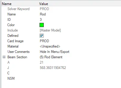
Properties for Rod created in Hyperbeam.
8. After Assigning properties to all the elements created in HyperBeam, we now change the view from 1D Traditional Element Representation to 1D Detailed Element Representation. After this, we area able to view the inserted Rod, Bar and Beam in the model.
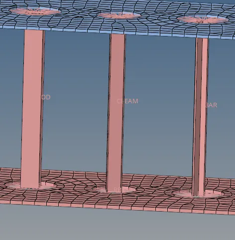
Rod, Beam, Bar
9. After this, we then go on to create the Spring elements on the model. To perform this, we need to use the Spring command in the 1D tab.

Spring command
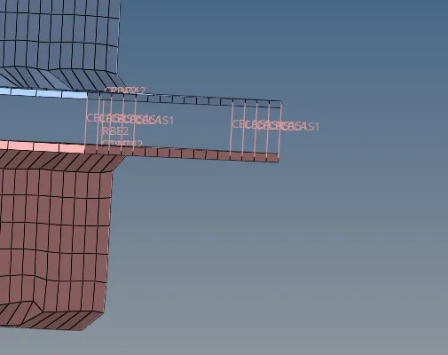
Spring command output
10. After the creation of the sprring element we need to add mass at the two RBE connections made. To perform this, we need to use the Mass command under the 1D tab.

Mass Command
11. The final Model will look something like this:
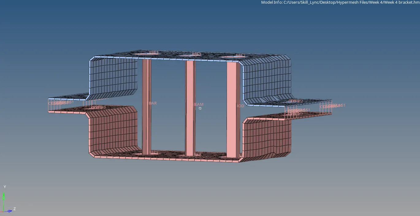
Final Product
- Conclusion: I would like to conclude by stating that we learnt how to take a mid surface of a product and the process to how create various 1D elements like the Rod, Beam, Bar and even the spring. I also understood the theoretical difference between the two Rigid Body Elements (RBE2 and RBE3)