Week 4 Challenge
(1)
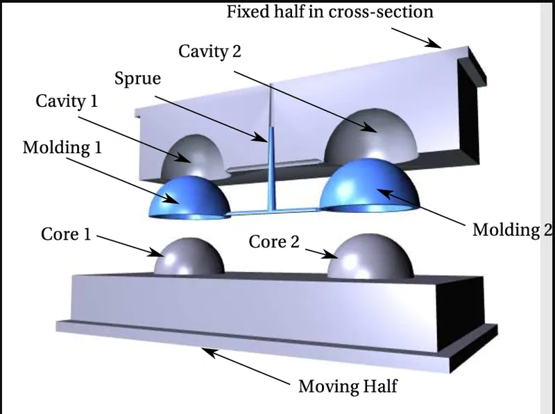
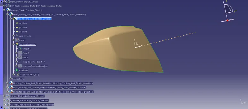
Tooling Direction : Tooling direction is the direction in which the mold pulls apart. The mold is made of two separate piece- Core and Cavity. Here, the core moves apart from the cavity along the direction of tooling axis.
(2)
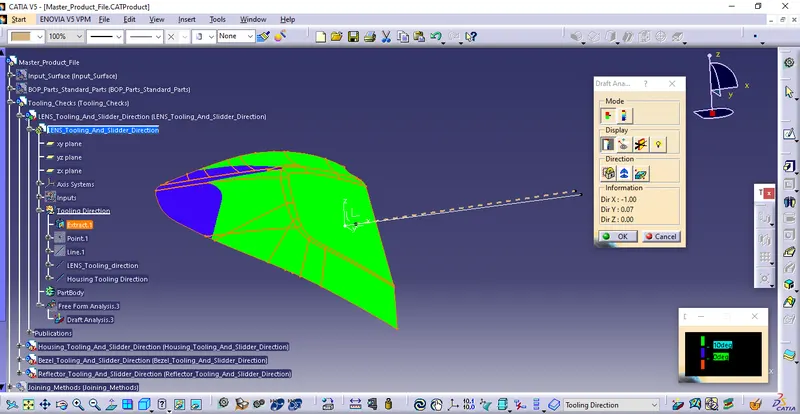
- The draft analysis of Class-A surface of Lens has shown in below image.
- here, the draft angle = 10 degree. is shown with green portion and the Blue portion is having less than 10 degree draft angle. If Red colour appears on surface then that will be bad surface portion and very difficult to mold.
(3)
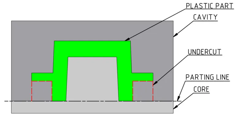
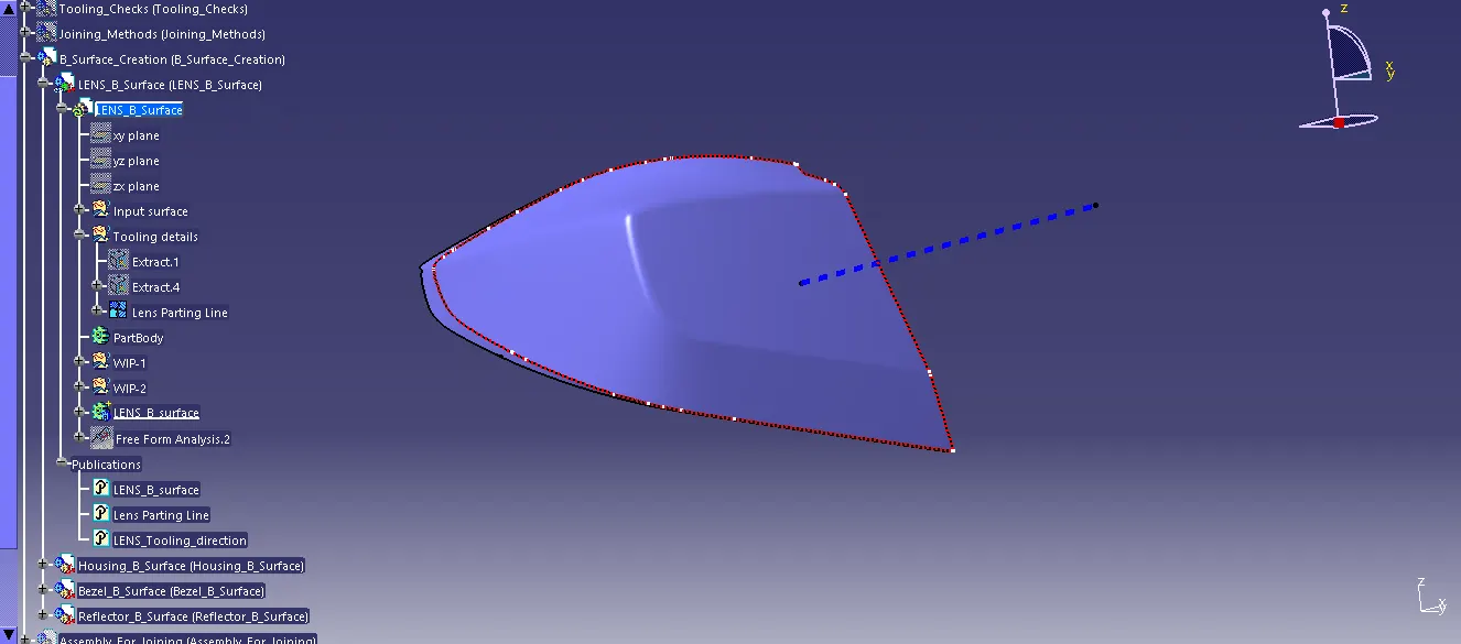
Parting Line : It is the line which divides the mold in two parts - core & cavity. In this Parting line Core & cavity comes together and also changes the draft angle.
(4)
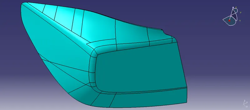
Class-B Surface :
- Take an offset = 4mm from the class_A surface.
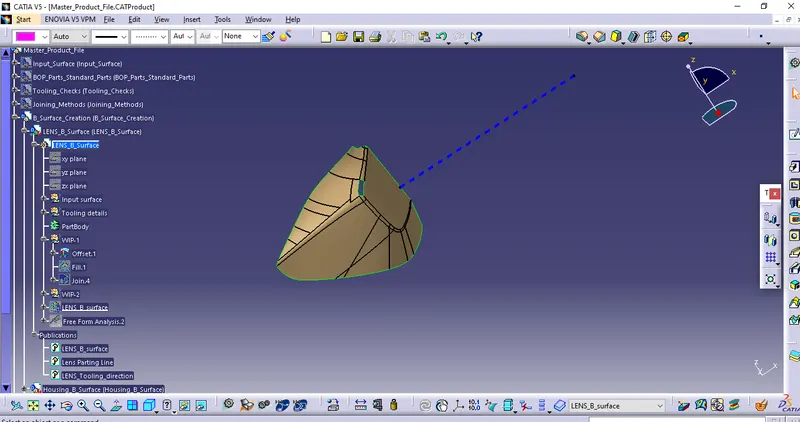
- Fill the surface to get desired offseted Class_A surface for making Class_B surface.
- make the Tooling Axis. along which Draft analysis will be done.
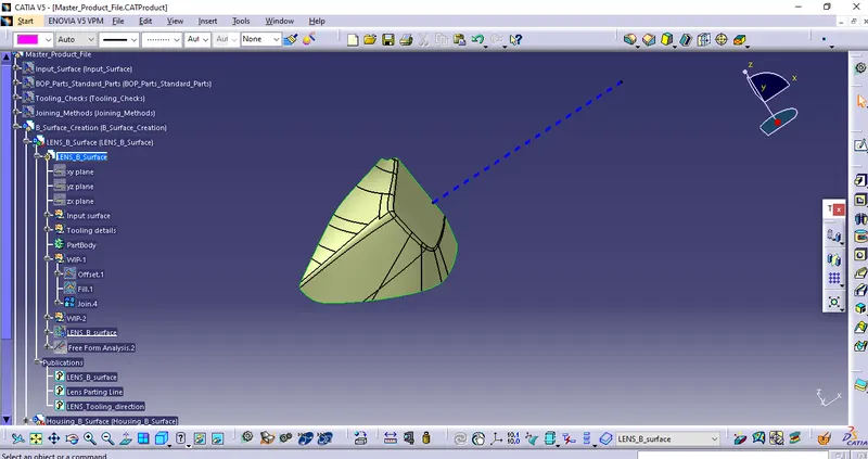
- Create Boundary on the class A_surface and use Sweep command.
- It is a Class_C surface.
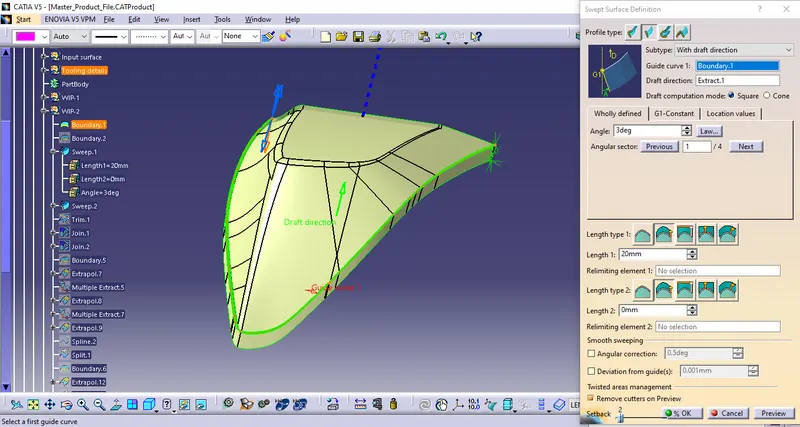
- use Join, Split, Trim and Closed surface comand to get the desired Class_B surface.
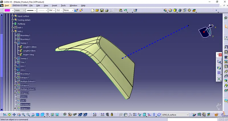
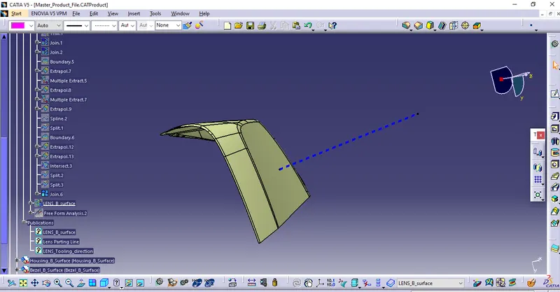
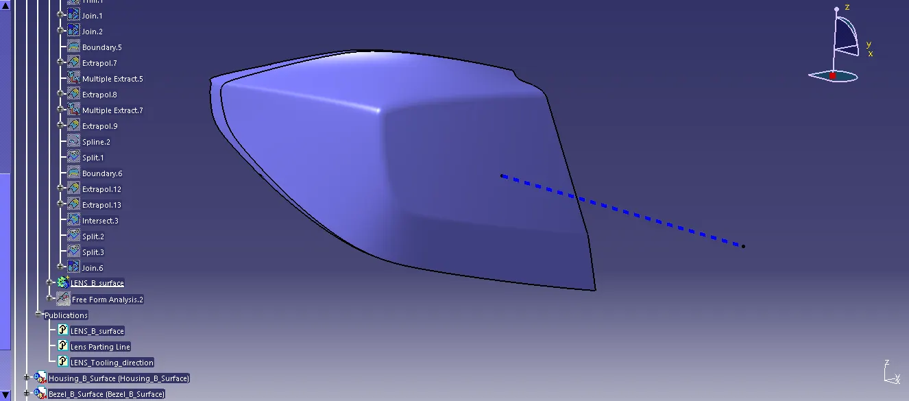
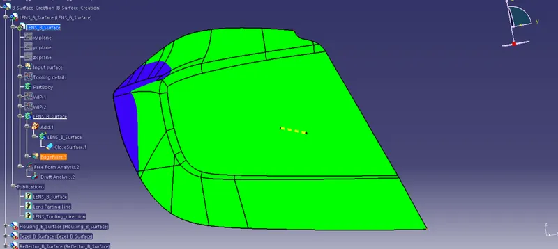
This is Class_B surface
Draft analysis of Class_B surface having draft angle =10 degree.
(5)
Parting Line of thickened LENS is represented bu Red colour dotted line.
Final Report
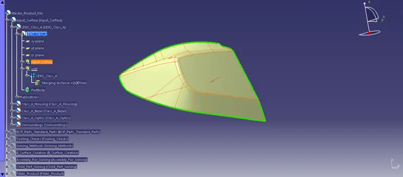
- Since, we have given the A-surface of Lens, so go to Generative Shape Design workbench check the surface clearity Join the all surface together with merging distance = .001mm.
- Create Tooling Direction of Class_A surface.
- Create Class_B surface by using operations by offseting the A_surface.
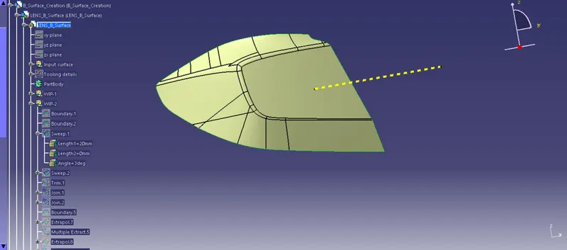
- Create class_C surface by using Sweep command which connects the B_surface and A_surface.
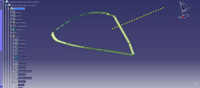
- Joined all surfaces Together to get the desired Lens.
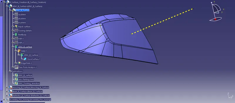
Welding Channel :
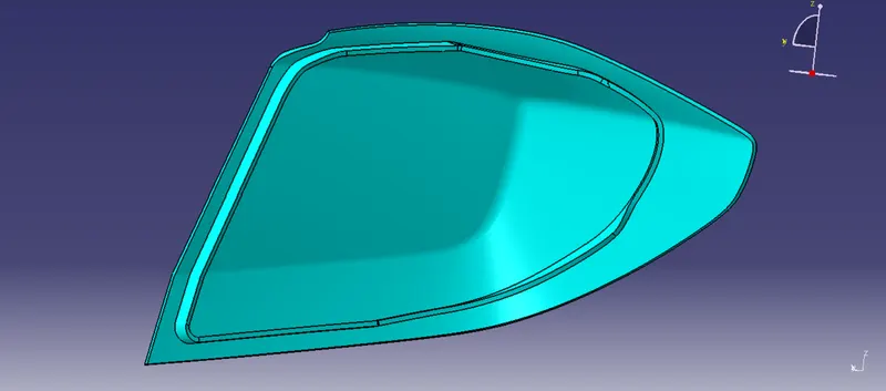
After the the Lens, Create the welding channel as -
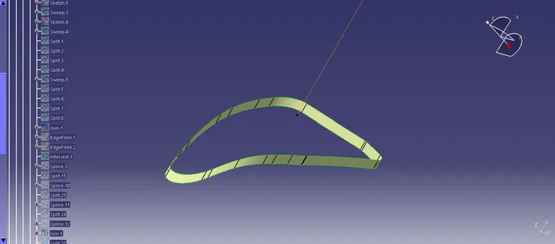
- Extract the SURFACE and the sketches for welding channel.
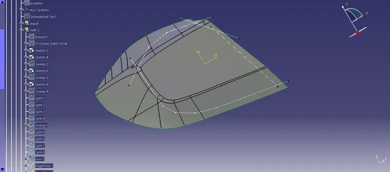
- use Sweep command along the Tooling direction.
- Join these sweeped surfaces by using split, trim operations.
- apply appropriate fillet at the edges.
- now, make an Intersection between the Class_A surface and this joined surface.
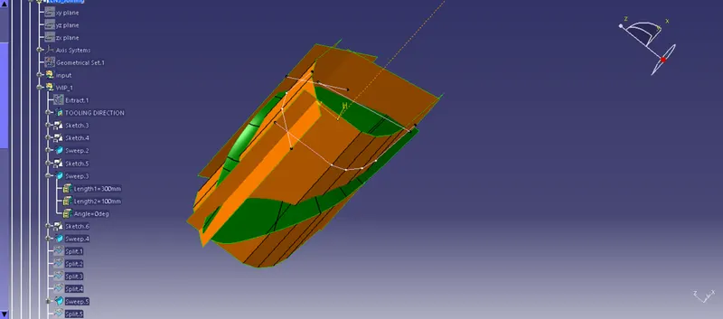
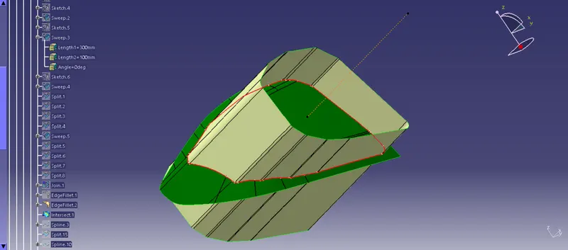
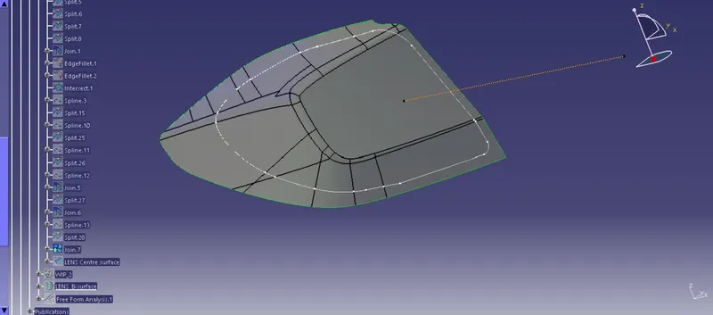
- again, sweep this intersection along the Tooling direction.
- Apply Thickness to the surface.
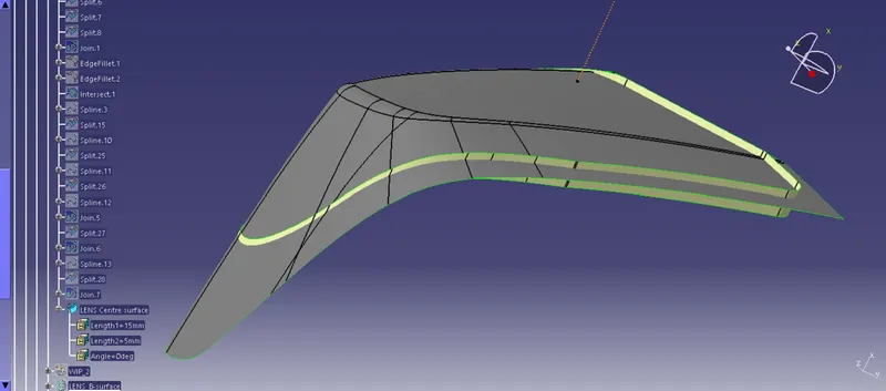
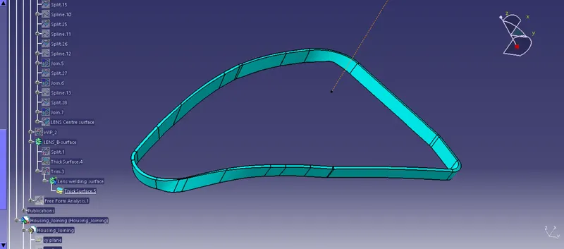
This is LENS Welding surface
- now, surface Offset=0.5mm by extracting of welding surface
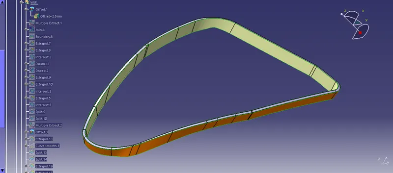
- use the Offset, split, Trim, Join operations to get the Housing Surface.
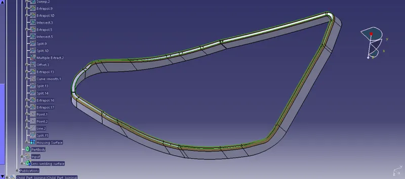
- make the Union Trim operation of this welding surface to the LENS.
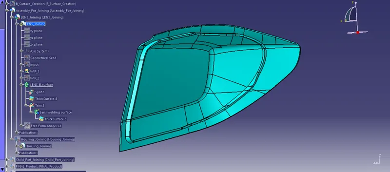
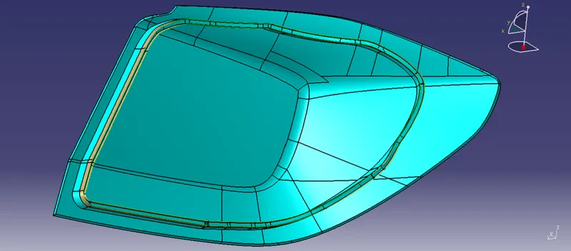
Lens with Housing
- Draft analysis is done with draft angle = 10 degree along the Tooling direction. the green surface indicates the draft angle having 10 degree and Blue represents Draft angle is less than 10degree.
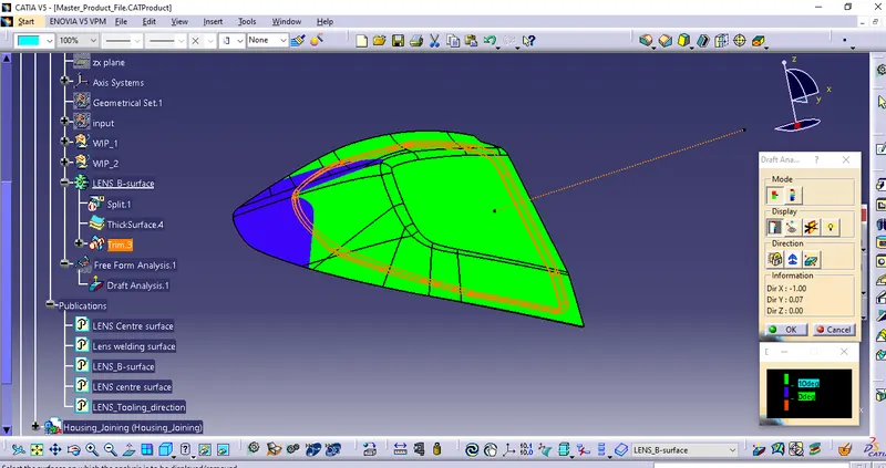
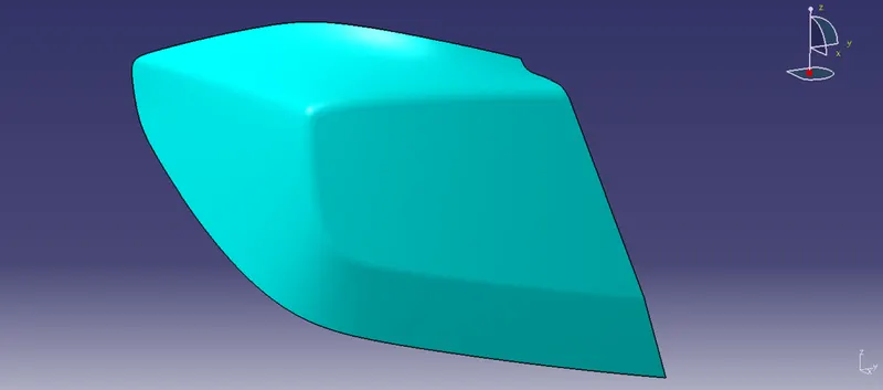
Different Views