Week-4 : Basic Calibration of Single cylinder CI-Engine
AIM :
Basic calibration of single cylinder CI – engine.
OBJECTIVES :
1. Compare SI vs CI engine and list down the differences.
2. Explain the following parameters in detail.
- BSFC
- Exhaust Temperature
- A/F Ratios
3. Change MFB 50 and observe impact on performance.
DIFFERENCE BETWEEN SI & CI ENGINES :
|
Sl No. |
SI Engine |
CI Engine |
|
1. |
SI engine is known as the Spark Ignition engine. |
CI engine is known as the Combustion Ignition engine. |
|
2. |
The fuel used here is Gasoline or Petrol. |
In CI engine the fuel used is Diesel. |
|
3. |
The compression ratio is 6 to 9. |
The compression ratio is high around 15 to 20. |
|
4. |
This is light in weight because of the low pressure developed here. |
This is heavy in weight because of the high pressure developed here. |
|
5. |
Low vibration and Noise here. |
Here more vibration and noise. |
|
6. |
SI engine works on the Otto cycle. |
CI engine works on the Diesel cycle. |
|
7. |
The speed is higher in the SI engine. |
The speed is low in the CI engine. |
|
8. |
Thermal efficiency is low or average. |
Thermal efficiency is high. |
|
9. |
Air and fuel are used during the intake process |
but here only air is used during the intake process. |
|
10. |
This is kind of cheaper in price. |
This we get higher in price. |
|
11. |
This is also called a constant volume cycle. |
This is called a constant pressure cycle. |
|
12. |
Petrol fuel has a high self-ignition temperature. |
Diesel fuel has a self-ignition temperature but it’s low. |
|
13. |
Knocking takes place at the end of the combustion. |
Knocking takes place at the beginning of the combustion. |
|
14. |
A homogenous mixture of fuel. |
A heterogeneous mixture of fuel. |
|
15. |
Petrol fuel is used in aerospace and automobiles. |
Diesel fuel used in heavy vehicles such as lorries, buses, and trucks, more. |
|
16. |
SI engine fitted with carburettor and spark plug. |
CI engine fitted with injection or fuel injected pump. |
|
17. |
Here ignition of air-fuel mixtures takes place by an electric spark produced by a spark plug. |
But here air-fuel take place by injection of fuel into the hot compressed air. |
|
18. |
Temperature range here 250 to 300-degree celsius. |
In CI engine Temperature 600 to 700 degree celsius. |
|
19. |
In the SI engine, Specific fuel consumption is more. |
Here in the CI engine, the specific fuel consumption is less. |
Model Comparison in GT – SUITE :
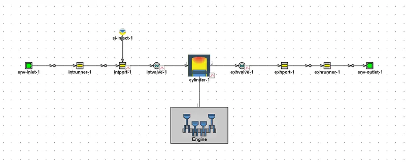
The inbuilt models of a single cylinder SI engine and CI engine in GT – SUITE are as follows.
1. SI – Engine
2. CI – Engine
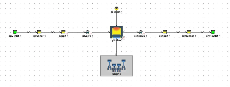
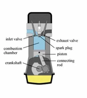
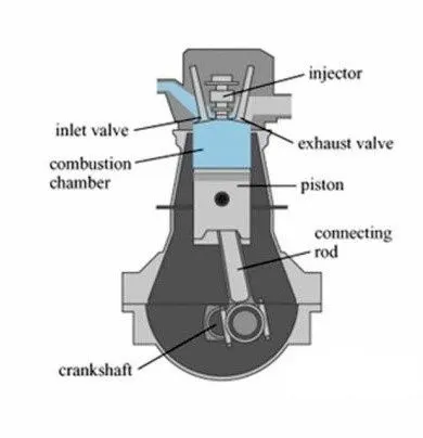
The basic difference between the two is the position of the fuel injectors. In SI engine, the fuel and air mixture enters the combustion chamber in the form of a homogeneous mixture. Whereas in the CI engine, air enters the combustion chamber, after which the fuel is injected and thereby forming a heterogeneous mixture.
With reference to the single cylinder CI – model shown above, we talk about the various related parameters such as,
1. BSFC
Brake-specific fuel consumption (BSFC) is a measure of the fuel efficiency of a combustion engine which burns fuel and produces rotational power. It is the rate of fuel consumption divided by the power produced.
`"BSFC" = r/P`
Where,
`r` = Fuel consumption rate in grams per second (`g`/`s`)
`P` = Power produced in watts (`W`).
2. EXHAUST TEMPERATURE
Exhaust gas temperature is a measure of heat in the cylinder during combustion, and is most commonly measured close to the head. As the temperature of the exhaust gas varies with the ratio of fuel to air entering the cylinders, it can be used as a basis for regulating the fuel/air mixture entering the engine.
There are lots of consequences which high exhaust gas temperature can cause to the engine parts, these are:
- Exhaust valve life time reduces up to 50% due to the high temperature.
- Cylinder liners wear more faster as required.
- Piston rings and piston itself might wear down or get damaged.
- High EGTs also contribute to knock.
3. A/F RATIO
Air fuel ratio is defined as the ratio of air and fuel of a mixture prepared for combustion.
When you press the accelerator pedal in a diesel engine, this drops the air/fuel ratio. Significantly more fuel is injected relative to the air ingested, which increases horsepower. Soot is created when diesel engines operate in low air/fuel ratios, which is why you may see black smoke from diesel trucks when they floor the throttle pedal.
A diesel engine generally operates from 18:1 to as high as 70:1, and is capable of operating in super lean ratios.
CI ENGINE CALIBRATION :
Considering the example of a single cylinder CI engine model as a reference, we carry out the calibration.
The various parameters for the modelling are defined as follows.
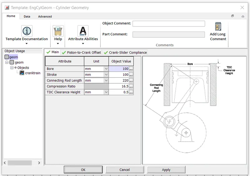
1. Cylinder Geometry
The cylinder geometry parameters such as the bore, stroke and connecting rod length are defined as follows.
2. Diesel Injector
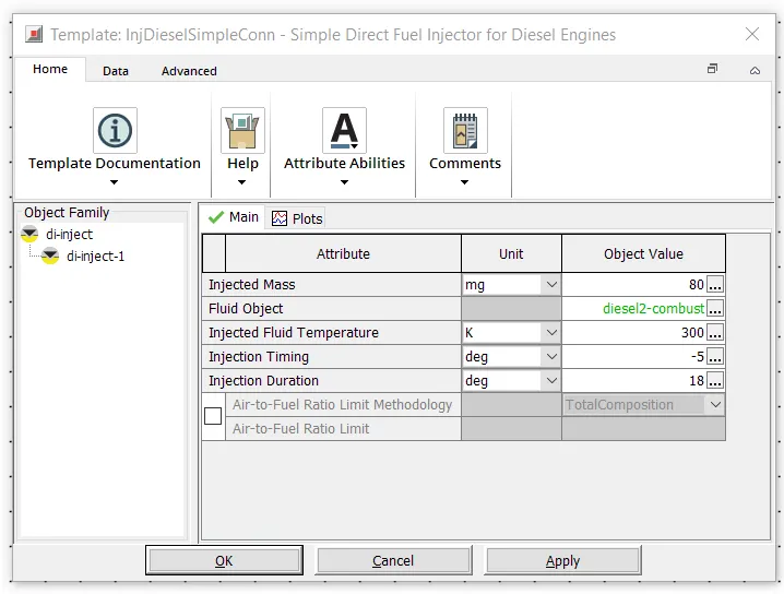
This injection connection is designed for direct-injection diesel engines when detailed injection data is not necessary. The basic goal of this injector is to deliver the desired amount fuel needed for combustion. It can be used with non-predictive combustion models, or with Measured Cylinder Pressure and TPA (Three-Pressure-Analysis) cylinder pressure analysis options.
3. MFB – 50 (Mass Fraction Burned)
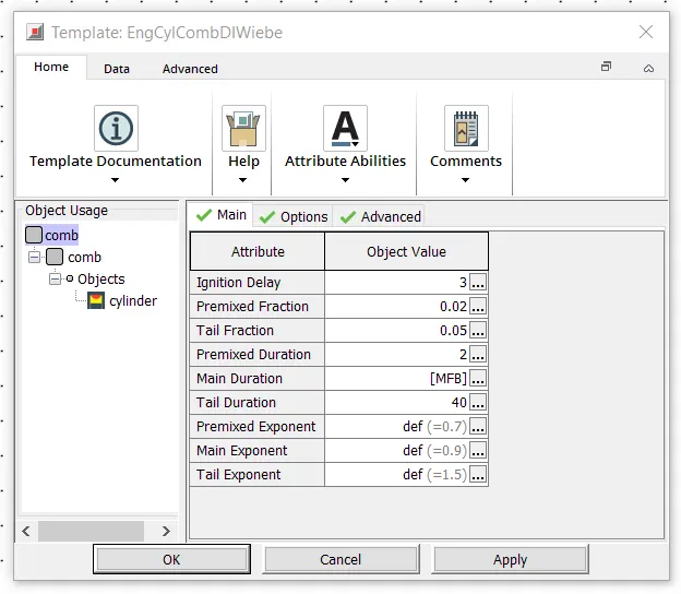
The energy conversion during a combustion cycle can be described by the Mass Fraction Burned (MFB) at a specific crank angle degree (CAD) and the MFB, in turn, can be used by feedback control systems. In IC engine, the MFB depends on engine geometry, engine speed, A/F, ignition angle, residual mass etc. Measuring and controlling the result can compensate many variables that affect the combustion process compensated on an individual cylinder basis.
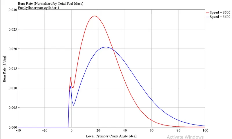
The determination of MBF is commonly based on burn rate analysis. In this challenge, we vary the MFB value by setting the duration in crank-angle degrees of the main diffusion burn (main duration) as a parameter, so as to compare the differences between MFB 35 and MFB 50.
CASE SETUP :
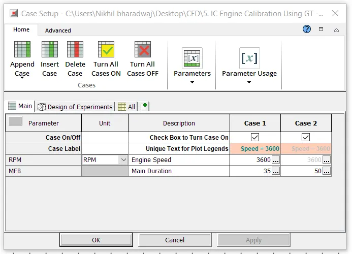
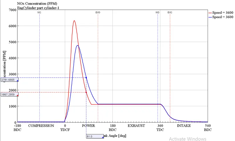
For a constant engine speed, we setup two cases representing MFB – 35 and MFB – 50, so as to compare the results obtained for each of the two cases.
RESULTS :
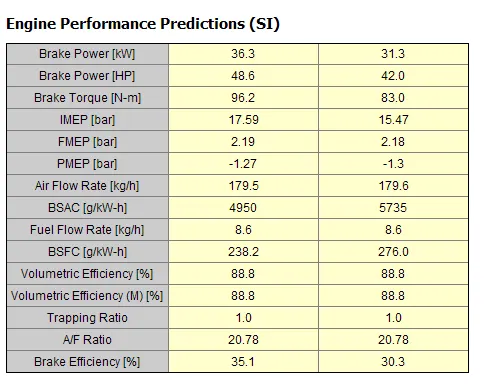
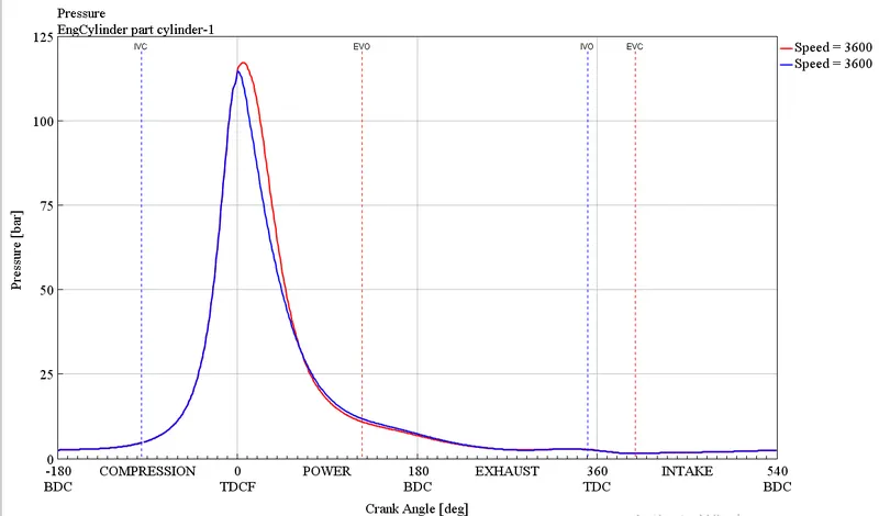
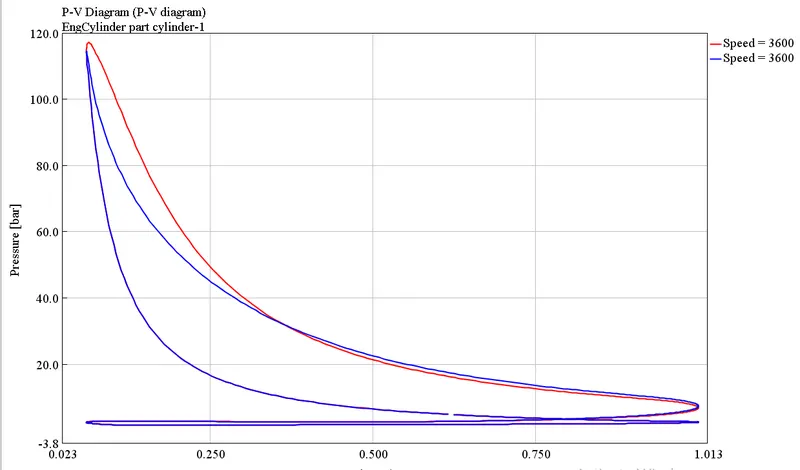
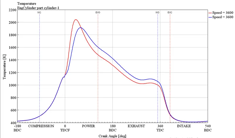
By running the simulation for the above mentioned parameters and post – processing the results, we obtain the following results.
Pressure :
P – V Plots :
Temperature :
Burn Rate :
NOx Concentration :
CONCLUSIONS :
A single cylinder CI engine has successfully been modelled and the various related parameters have been explained in detail.
Two case studies representing the values of MFB – 35 and MFB – 50 have been carried out as shown. From the results, we can observe that as the MFB value increases, there is a decrease in the burn rate, signifying that the fuel burns slower as higher MFB values. Consequently, at higher MFB values, the Brake Power, Brake Torque and IMEP of the engine reduce and thereby leading to a lower NOx concentration value.