Week-4 : Basic Calibration of Single cylinder CI-Engine
Basic Calibration of Single Cylinder CI Engine
Aim:
To compare the differences in developing a single-cylinder SI and CI engine model in GT-Suite and determine the influence of the MFB parameter on the CI engine performance.
Introduction:
The Spark Ignition (SI) and Compression Ignition (CI) engines were developed to convert chemical energy to mechanical work. However, they employ different operation principles to achieve their target. Some of the key differences between the two engines are summarized in the table below [1]:
|
SI Engine |
CI Engine |
|
It operates based on the Otto Cycle |
It operates based on the Diesel Cycle |
|
The heat addition takes place at a constant volume |
The heat addition takes place at constant pressure |
|
It uses a spark plug to ignite the fuel |
It relies on the auto-ignition of the fuel for combustion |
|
It operates in the low compression ratio regime (9 -11) |
It operates with high compression ratios (14 – 22) |
|
These engines are designed with a directed port for tumble fuel injection |
These engines require a helical port for better performance |
|
They have low noise production and provide high driving comfort |
They have a high fuel efficiency |
|
Knocking is the major problem |
Detonation is the major drawback |
|
High engine speed (1000 – 8000 rpm) |
Low engine speed ( 1000 – 4000 rpm) |
|
Major emissions include CO, HC, NOx |
Major emissions include CO, HC, NOx, Soot |
|
They use fuels with high octane number |
They use fuels with a high cetane number |
|
Common fuels include Petrol, LPG, and CNG |
Common fuels include Diesel, biodiesel |
Model Development:
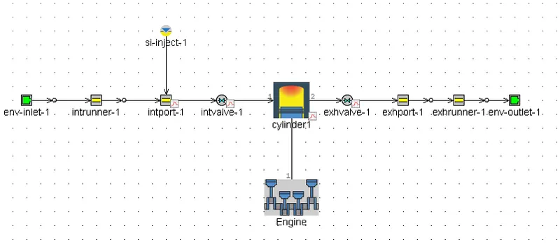
GT-Suite was used to develop a 1D model of both engines. The following figures show the completed model of the engines:
SI
CI
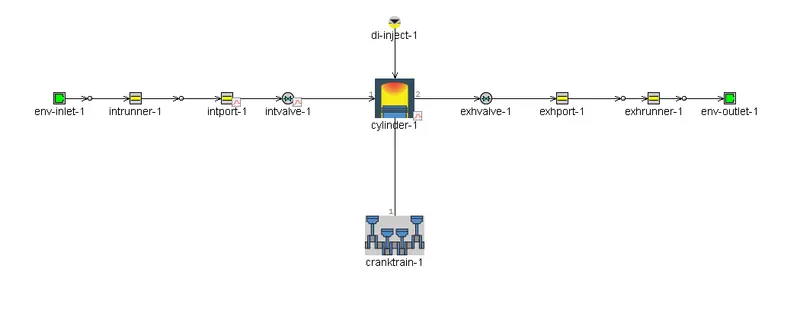
The following table summarizes the major differences in their setup
|
Component |
Parameter |
1 cylinder SI |
1 cylinder CI |
|
Env-inlet |
Pressure (bar) |
1 |
2.4 |
|
Temperature (K) |
300 |
350 |
|
|
Length (mm) |
300 |
120 |
|
|
Intake Runner |
Wall Temperature (K) |
300 |
350 |
|
Fuel |
Type |
Indolence |
Diesel |
|
Fuel Injection |
Method |
Fuel is injected into the intake port. Air fuel mixture enters the combustion chamber |
Fuel is directly injected into the combustion chamber. Mixing takes place inside the combustion chamber |
|
Combustion |
Model |
EngCylCombSIWieb |
EngCylCombDIWieb |
|
Cylinder |
Bore (mm) |
86 |
100 |
|
Stroke (mm) |
86.07 |
100 |
|
|
Compression ratio |
9.5 |
16.5 |
|
|
Connecting Rod (mm) |
175 |
220 |
|
|
Clearance Height (mm) |
1 |
0.5 |
|
|
Env-outlet |
Pressure (bar) |
1 |
2.4 |
|
Temperature (K) |
300 |
350 |
The CI engine uses a turbocharger, but it was not modeled. Hence a higher inlet pressure was specified in the env-inlet to include the presence of a turbocharger.
The SI engine has a longer inlet pipe to prevent the reverse flow of the fuel from the cylinder into the inlet runner. The reverse flow will increase the air-fuel ratio and reduce its performance. This is not a problem in the CI engine because the fuel is injected directly into the cylinder during the power-stoke.
Comparison of specific parameters:
Both the models were simulated at 3600 rpm, and the important parameters are compared
|
Parameter |
SI Engine |
CI Engine |
|
Brake Specific Fuel Consumption (g/kW-h) |
241.8 |
238.3 |
|
Exhaust Temperature (K) |
1212 |
1045 |
|
Air-Fuel Ratio (-) |
14.5 |
20.78 |
|
Brake Power (kW) |
16.7 |
36.3 |
|
Brake Efficiency (%) |
32.6 |
35.1 |
|
NOx (ppm) |
6.97 |
1110.19 |
|
CO (ppm) |
10709.1 |
2.33 |
The CI engine operates at a higher compression ratio, and hence the brake power and efficiency are higher than the SI Engine. This high compression ratio also leads to a lower BSFC. At the same time, the CI engine often operates in the lean region leading to higher NOx emissions.
Influence of the MFB50 on the CI Engine performance:
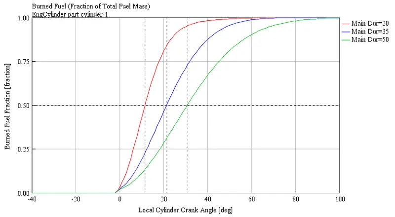
Mass Fraction Burned (MFB) in each engine cycle is a normalized quantity that describes the probes of the release of chemical energy as a function of crank angle. It varies from 0 to 1 and shows how the in-cylinder combustion progresses with crank angle.
In the CI engine model, the parameter “main duration” in the combustion object is changed to vary the MFB. The main duration is the duration in crank angles where controlled combustion is taking place.
MFB50 is used to denote the crank-angle where 50% of the fuel is converted to energy. This is an important parameter in comparing the combustion control and duration of different fuels.
Three simulations were performed by changing the main duration from 20 to 50, and the corresponding MFB50 values are shown in the table below
|
Main Duration (-) |
20 |
35 |
50 |
|
MFB50 (deg) |
11.5 |
21.5 |
31 |
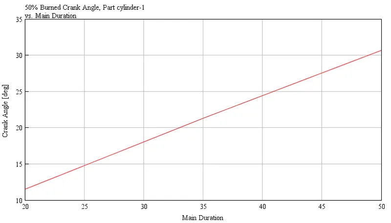
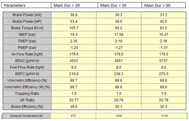
When the MFB50 was increased, the following changes were observed:
- The Brake power and torque decreased
- The BFSC increased
- The Brake efficiency decreased
- The Air-Fuel ratio remained the same
- The Exhaust Temperature increased
The Mass Fraction Burned (MFB) for the three cases were plotted as shown in the figure below.
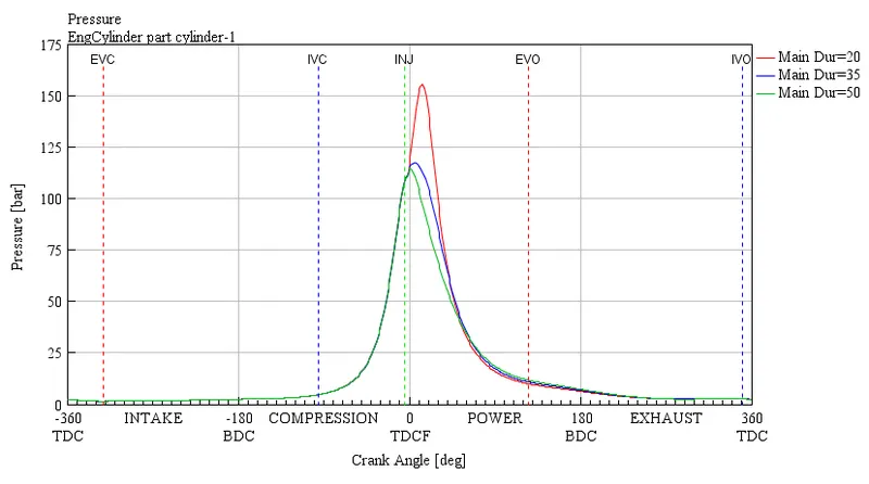
As observed from the above figure, the in-cylinder pressure also decreased with the increase in MFB50, leading to lower power output.
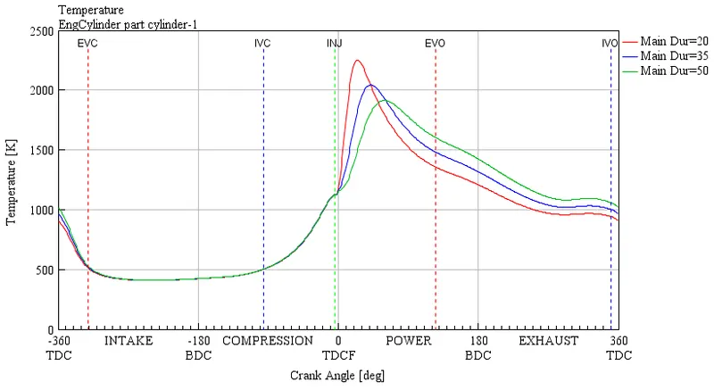
Conclusion:
In this project, the SI and CI engine characteristics were compared and summarized, including their modeling strategies. In addition, the influence of the MFB50 on the CI performance was evaluated by modifying its combustion model parameters. An increase in the MFB50 signifies that the fuel burns slowly, and hence the power output was less.
References: