To model Stateflow logic for Washing machine cycles and Gearbox in a vehicle to shift gear at appropriate speed using Simulink.
Aim:
- To implement control logic of a “washing machine” using Stateflow in Simulink.
- To model “Gear shift” logic using Stateflow in Simulink.
Objectives:
- To model working of a washing machine using Stateflow for the below given logic:
- If the power supply is available, the system gets activated
- If the Water supply is not available, stop the process & indicate through LED
- Soaking time should be 200s followed by Washing time of 100s.
- Then rinsing happens for next 20s & dryer runs for 50s
- To model Gear Shifting of a vehicle for given circumstances below:
|
Speed Range (kmph) |
Gear |
|
0 to 15 |
1 |
|
16 to 25 |
2 |
|
26 to 40 |
3 |
|
41 to 60 |
4 |
|
Above 61 |
5 |
Theory:
What is Stateflow?
Stateflow is an environment for modelling and simulating logic based on state machines and flow charts. Stateflow lets allows us to combine graphical and tabular representations, including state transition diagrams, flow charts, truth tables, to model how your system reacts to events, time-based conditions, and external input and output signals to analyse the required output of the logic used in the charts.
With Stateflow we can design logic for supervisory control, task scheduling, and fault management related applications. Stateflow includes state machine animation, static and run-time checks for testing design reliability and comprehensiveness before implementation [1].
Part 1: Washing machine Stateflow model
As we use washing machine in our daily life. It is designed with controlled systems that has different cycles like filling the water, soaking, tumble, and spinning, which washes the clothes and in the end it dries the clothes by removing the excess water in the clothes, and in some advanced machines there is even a facility to completely dry the clothes by the aid of heater. As the given task for this project, it was required to design a control logic by using the given parameters below:
- If the power supply is available, the system gets activated
- If the Water supply is not available, stop the process & indicate through LED
- Soaking time should be 200s followed by Washing time of 100s.
- Then rinsing happens for next 20s & dryer runs for 50s
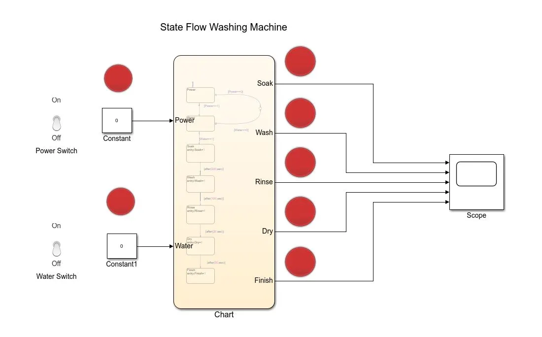
The Simulink model showing the Stateflow chart, input ports and switches to turn ON and OFF the power and water with the output ports having all the washing machine states such as Soak, Wash, Rinse, and Dry, which are connected to a scope to visualise the output signals with the LEDs connected to all the output ports to check if that state is ON or OFF. The Simulink model can be seen below.
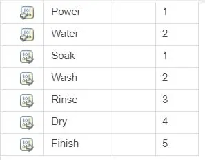
Designated input and output ports:
Simulink model:
A Stateflow was designed as shown below by using “Charts” in the Simulink program, where the state blocks were used to input the condition of the working of each cycle and how long that cycle is supposed to run by giving the delay of that state.
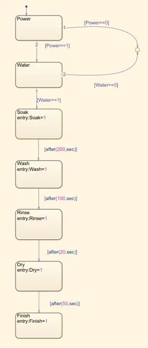
Here in the chart the first state was chosen was Power, where it detects if the input power is present or not, else the machine will not turn on. Similarly, a state for water was used to detect if there is input of water or not else the machine will not turn on. Hence by making them as Input ports to the state flow and were connected to the ON and OFF toggle switches which in general provides 0 or 1 as a signal as 0 is no input and 1 is input to the system. Therefore, a condition at these two states were given as if there is input 1 then the machine will run, that means the signal will passed through to run the states ahead. And if there is no input, a junction was inserted where it was given a signal from power and water states of 0 which means if the input is 0 the cycle will not move forward and the function will be terminated, which means in Simulink if the switches are off with signal 0 the Stateflow will not work.
Thereafter, the state of Soak was added which was given a time delay of 200 seconds, that only after 200 seconds of soaking the machine will start the next step ahead. After 200 seconds of soaking the machine will go on to Wash mode where it will wash the clothes for another 100 seconds, therefore a time delay of 100 seconds was given at the washing state. After washing for 100 seconds, comes the Rinse state where the machine will rinse the clothes for additional 20 seconds and in the end the Dry state will dry the clothes for 50 seconds.
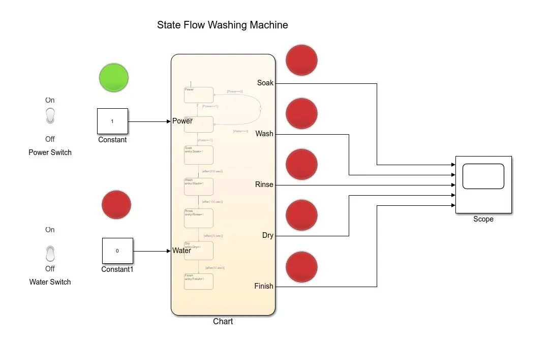
The first simulation carried out for 10 seconds was to check if the power is going in the circuit to activate the machine, however water was switched off, as it was just to check the power availability. As seen in the figure below, the power LED is ON and the water LED is off and rest of the output LEDs are off as we have programmed the circuit to only run if power and water both are ON.
Thereafter, the power and water switches were turned on for full functionality check of the logic. Shown below in the figure, where both the switches are turned ON, and the simulation was run for 10 seconds we can see both water and power LEDs are ON with the Soak LED ON. With power and water ON the soaking starts.
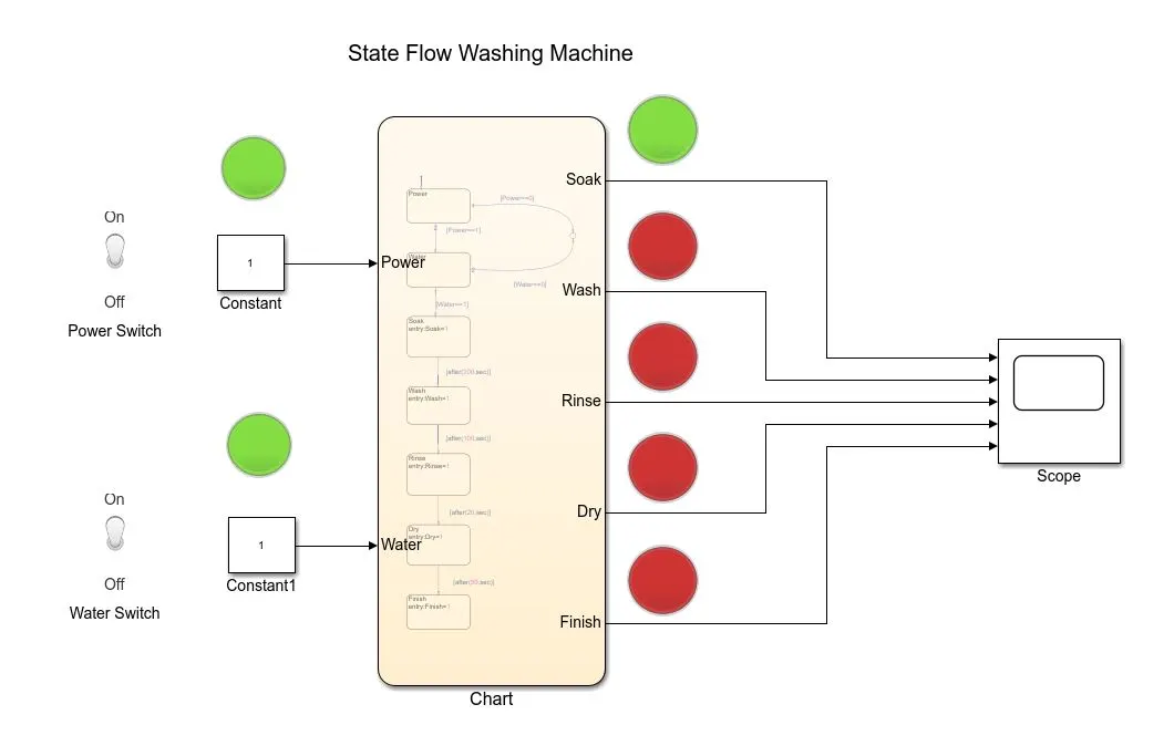
As the soaking period was 200 seconds the next simulation was ran for 210 seconds to check if the Wash cycle starts or not, the next figure shows us the washing LED ON, just right when the rinse cycle finishes, the washing starts and therefore turns ON the LED.
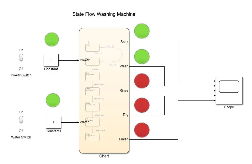
The next step was to check the functionality of the Rinse cycle for which the simulation was ran for 330 seconds where, right after the wash cycle the rinsing started which can be seen in the figure below.
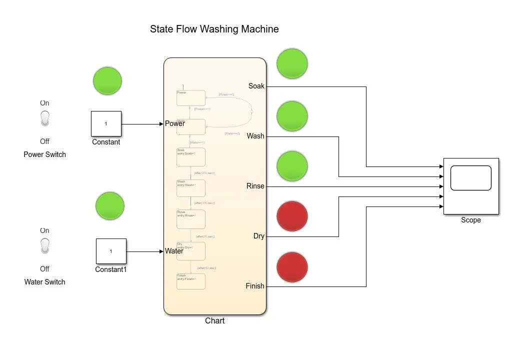
After rinsing the Dry cycle needed to start therefore the simulation was ran again for 380 seconds, as after 20 seconds of rinsing, the drying cycle has to start. The next figure shows us the Dry LED ON.
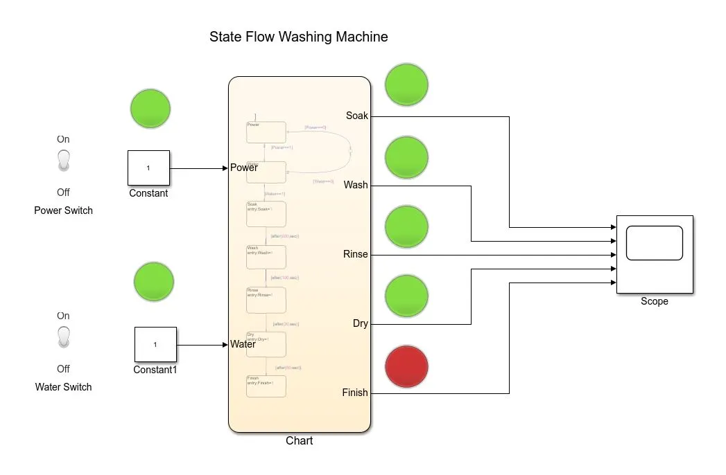
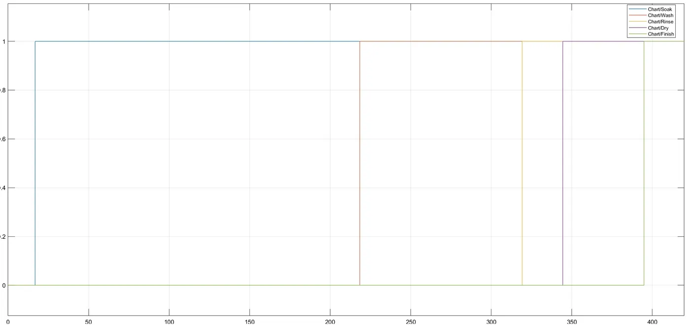
Once the whole cycle completes the Stateflow was given a Finish output to show that the whole cycle of 370 seconds has finished. The next figure shows is the finished cycle LED ON which means the cycle was finished. This last simulation was running for total of 380 seconds where we can see all the LEDs ON.
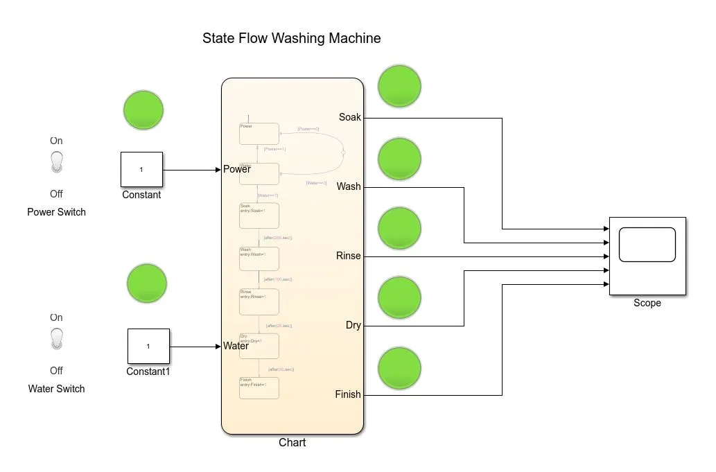
Hence we can say that the Stateflow model for washing machine was a success where all the cycles ran appropriately for the programmed time given at each state. The final scope output can be seen below.
Part 2: Gearbox Stateflow model.
In a vehicle a transmission plays an important role to give appropriate torque to keep the vehicle moving ahead or in reverse direction with proper traction. In the vehicle the change of the gears depends on the road or load conditions, for example if the vehicle needs to go uphill it needs more torque which can be appropriately provided by selecting proper gear. The transmission/gearbox is initially connected to the crank shaft through flywheel and the output of the gearbox is connected to the axle of the vehicle which gives drive to the rear wheels in the case of front wheel drive. Whereas in the rear wheel drive the drive is directly given to the rear wheels and the axle gives the drive to front wheels.
The following Simulink model was made following the given steps to change the gear according to the speed of the vehicle. The gear to engage at various speeds is as mentioned below.
|
Speed Range (kmph) |
Gear |
|
0 to 15 |
1 |
|
16 to 25 |
2 |
|
26 to 40 |
3 |
|
41 to 60 |
4 |
|
Above 61 |
5 |
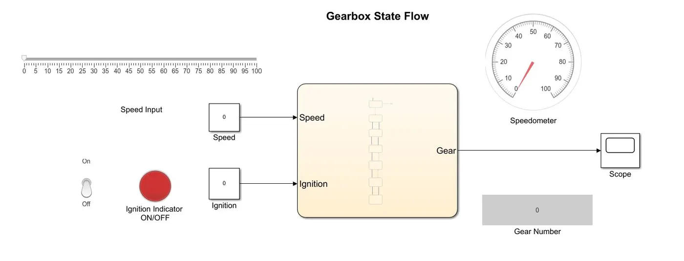
The Simulink model made with the Stateflow is shown below.
A Stateflow chart was made to change the gears according to the speed, where different states were programmed according to the speed of the vehicle. Initially ignition state was given to check if the ignition of the vehicle is ON or OFF, if the ignition was off the flow will be terminated at the junction provided. The Stateflow chart is as shown below.
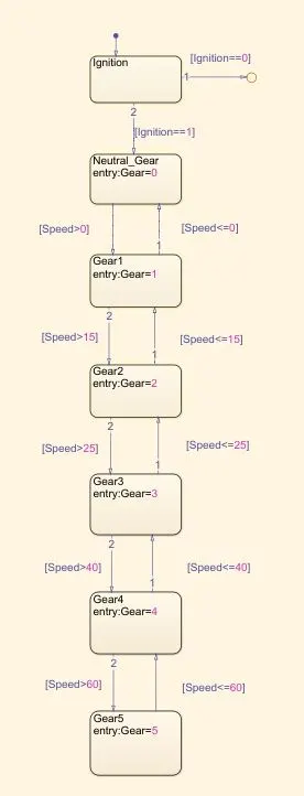
After the ignition state the Neutral Gear state was given for when the vehicle is at 0 kmph it will engage neutral gear. Thereafter Gear1 state was given where the speed condition was applied where if the speed of the vehicle is greater than 0 it will engage first gear and if the speed is lesser than or equal to 0 it will engage neutral gear. Two connections are made at each state for greater than or lesser than or equal to the assigned speed to engage the higher gear or to engage the lower gear.
Thereafter the second gear state Gear2 was implemented for the speed if the speed is greater than 15 kmph it will engage second gear else if lesser than 15 kmph it will engage first gear. Similarly, Gear3, Gear4, and Gear5 states were implemented with their respective speeds at that point of time.
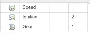
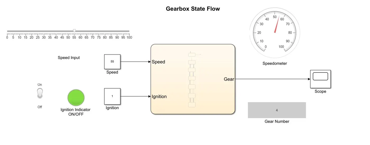
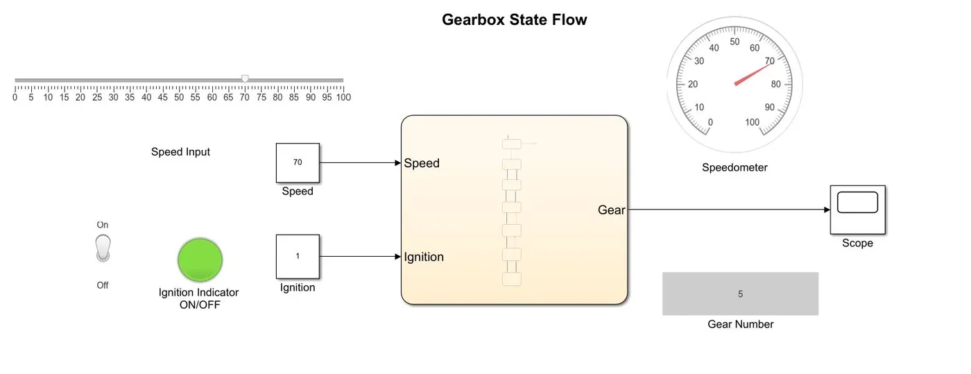
There are two input ports to this chart and there is one output port. One input port is given for the Vehicle Speed input to the gearbox which is given by the slider block of Simulink and one Vehicle Ignition switch input connection which is given by the Toggle Switch of the Simulink connected to the constant block. There is one output where it shows the gear number engaged in the gearbox at that point of speed, which is connected to the scope to observe the output and one display to display the gear engaged at that particular speed. The input and output ports given in this Stateflow is shown in the figure below.
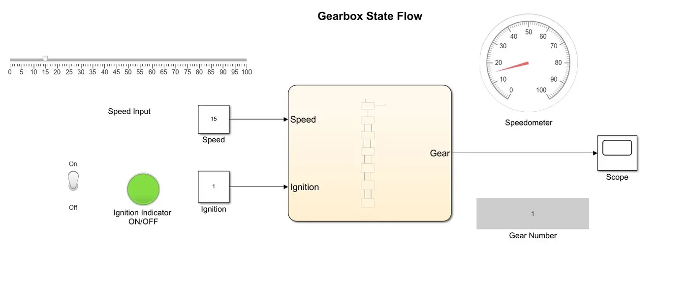
The simulation was generally run for 100 seconds. The first simulation of the speed 15 kmph was carried out which can be seen below, where first gear is engaged.
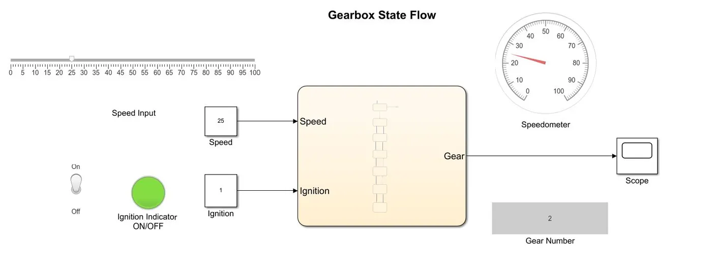
The second simulation was carried out at 25 kmph where Gear2 gets engaged.
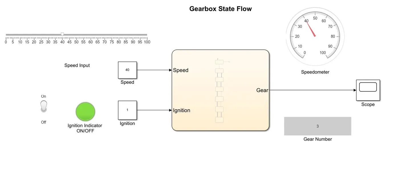
The third simulation was carried out at 40 kmph where Gear3 is engaged.
The fourth simulation was carried out at 55 kmph where Gear4 is engaged.
The fifth simulation was carried out at 70 kmph where Gear5 is engaged.
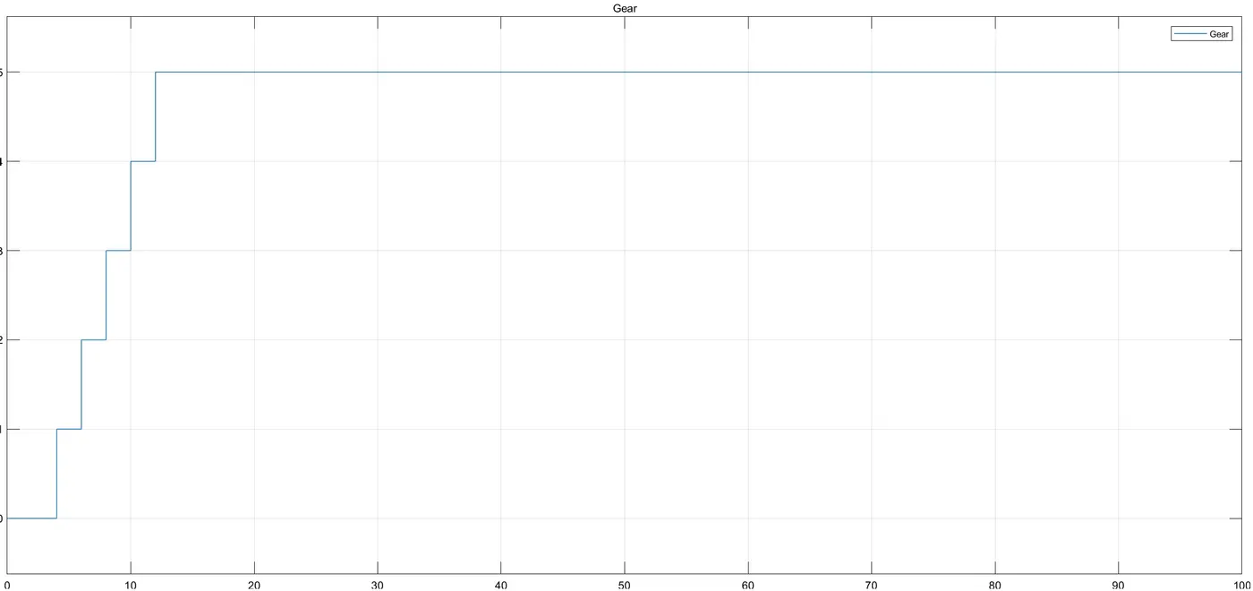
The output graph from the scope shows us the gradual up-shifting of the gears from 1st to 2nd to 3rd to 4th to 5th it does not go directly to 5th gear when the speed input for 70 kmph was applied for the simulation. This means that the gears are shifting as it is done in an actual vehicle. The final scope plot can be seen below.
From the above observations it can be said that the simulation for this Stateflow was a success and the required outputs were achieved.
Conclusions:
- The Stateflow simulation for washing machine logic was carried out successfully where it turned ON every stage at given time delay and it did not turn on if the water supply was OFF but when the power was turned ON it turned the supply ON which can be seen through LED turning green. The simulation was a success as all the states turned ON at given time which was observed in the final scope plot.
- The Stateflow simulation for the gearbox logic was carried out successfully where the gearbox engaged appropriate gear at the given speed and the gear number was displayed at the output. The simulation was a success as observed in the final scope plot, where the gears were engaged gradually.
References: