Week - 4
AIM:
The aim of this project is to understand the working of Stateflows and create two model with the given objectives.
OBJECTIVES:
- Implement control logic of a “washing machine” using Stateflow as per given sequence:
- If the power supply is available, the system gets activated
- If the Water supply is not available, stop the process & indicate through LED
- Soaking time should be 200s followed by Washing time of 100s.
- Then rinsing happens for next 20s & dryer runs for 50s
After all the processes have completed turn on the finished LED
Control logic of a “washing machine” using Stateflow
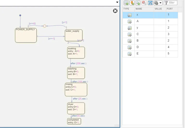
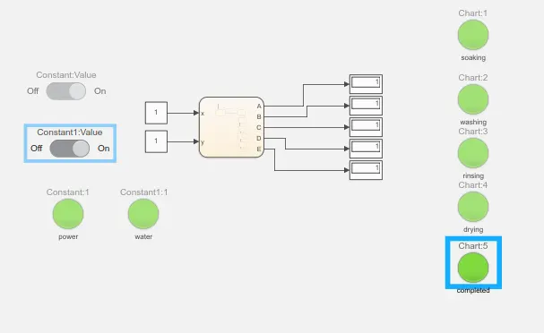
Powers supply state is created and if it is 1(PS==1) process is initiated. This is followed by the availability of the water supply(WS==1).
Next 4 states are created for soaking, washing, rinsing, and drying for 200s, 100s,20s and 50s respectively.
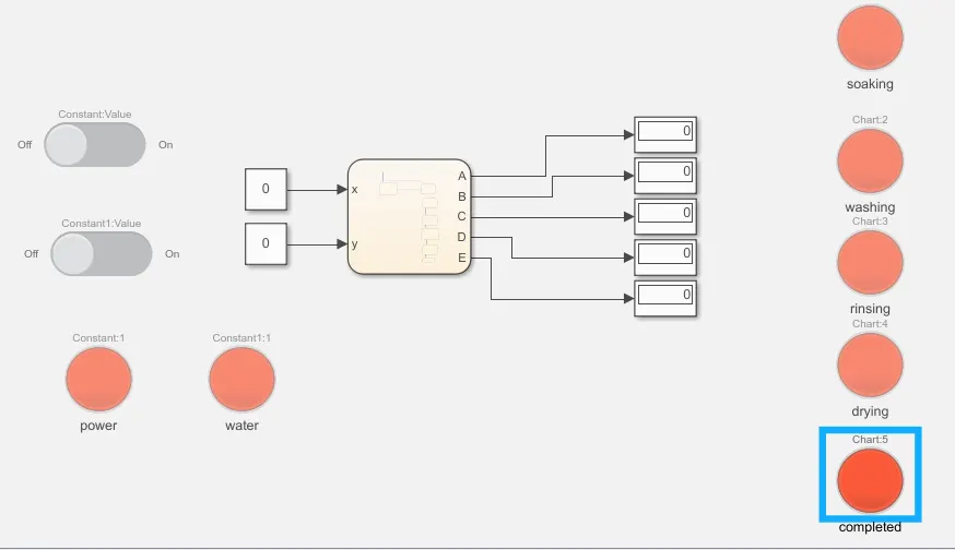
WHEN POWER SUPPLY=0 WATER SUPPLY=0
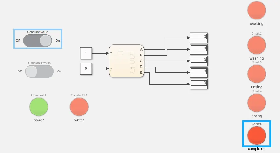
WHEN POWER SUPPLY=1 WATER SUPPLY=0
WHEN POWER SUPPLY=1 WATER SUPPLY=1
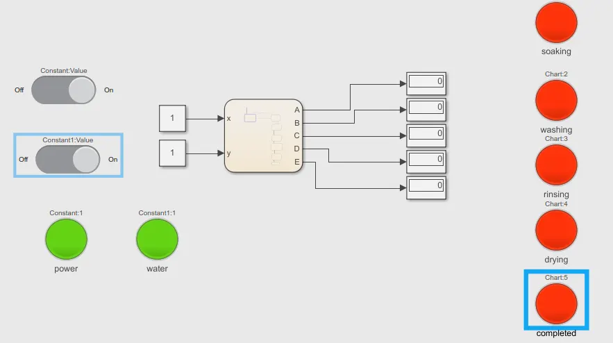
WHEN POWER SUPPLY=1 WATER SUPPLY=1 AND TIME=200s
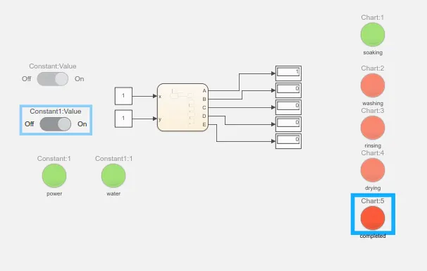
WHEN POWER SUPPLY=1 WATER SUPPLY=1 AND TIME=300s
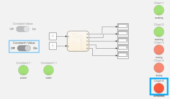
WHEN POWER SUPPLY=1 WATER SUPPLY=1 AND TIME=320s
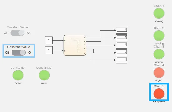
WHEN POWER SUPPLY=1 WATER SUPPLY=1 AND TIME=400s
OBJECTIVE 2:
Make a Simulink chart for the “Gear shift” logic as per below conditions:
Speed Range(kmph) Gear
0 to 15 1
16 to 25 2
26 to 40 3
41 to 60 4
Above 61 5
Give speed input while the simulation is running & display the gear number.
PROCEDURE:
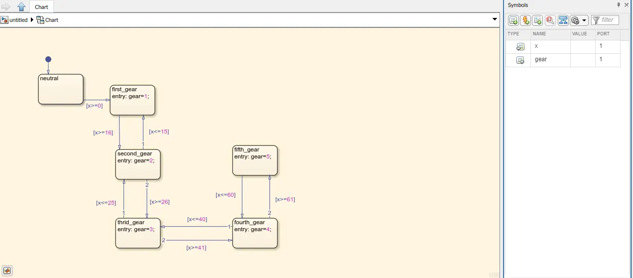
According to the given conditions, neutral state is created with default transition.
If speed is 0>x<15 = 1st gear is selected
If speed is 16>x<25 = 2st gear is selected
If speed is 26>x<40 = 3st gear is selected
If speed is 41>x<60 = 4st gear is selected
If speed is 60<x = 5st gear is selected
STATE FLOW CHART:
SIMULINK MODEL:
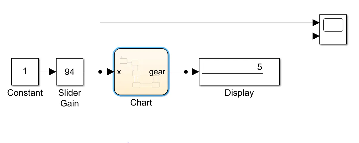
Slider gain block is used to change the speed for the movement of respective gear.
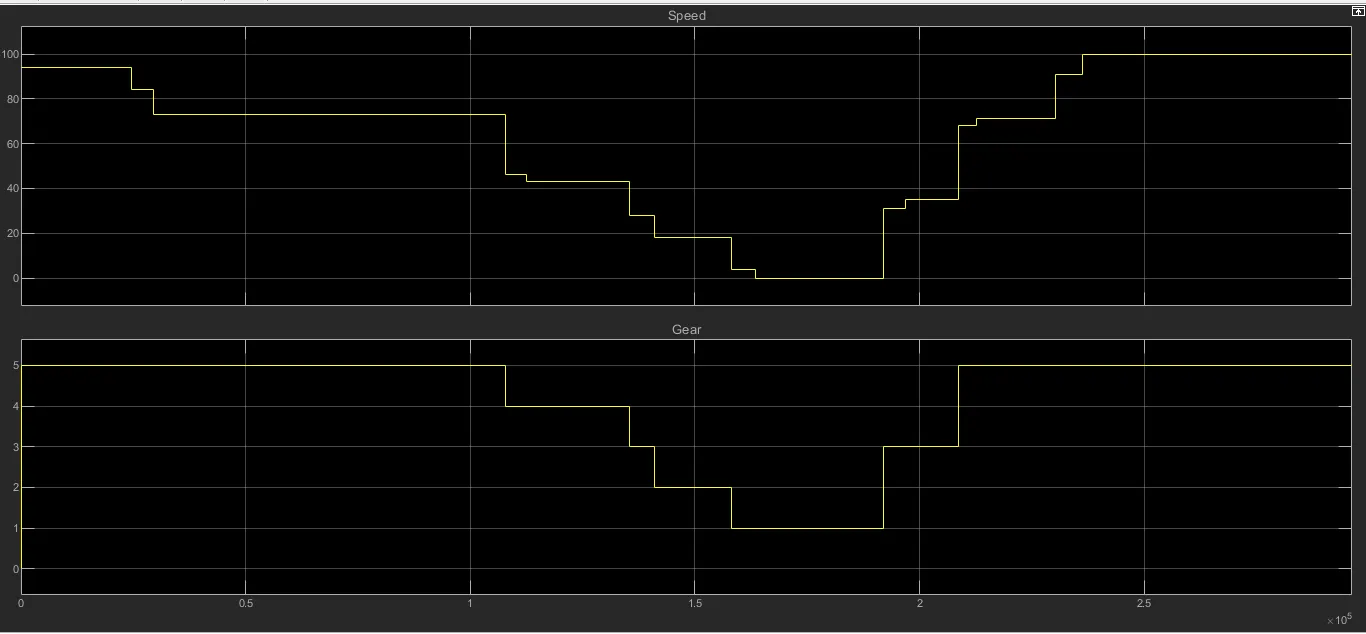
From the below graph, the upshifting and downshifting of gears based on the speed using the state flow chart is created.