Week - 4
Aim:
To implement and run Washing Machine using stateflow & create 'Gear Shift Logic' using stateflow.
Procedure:
Using SIMULINK software to run washing machine according to given condition as below,
1. Implement control logic of a “washing machine” using Stateflow as per given sequence:
- If the power supply is available, the system gets activated
- If the Water supply is not available, stop the process & indicate through LED
- Soaking time should be 200s followed by Washing time of 100s.
- Then rinsing happens for next 20s & dryer runs for 50s
After all the processes have completed turn on the finished LED
So to run the washing machine, contant block, slider gain, chart, display block and lamp blocks are used.
Initially two Constant block is connected to the chart block one for water supply and another for power supply, inside the chart we have sub-systems were the operation of the washing machine is expressed in stateflow command as power connection leads to water supply which connects to soaking operation for 200seconds then washing process is carried out for 100seconds, once the washing is completed it is operated to rinse for 20seconds and finally operation dryer is carried out, which is explained in the sub-system stateflow blocks as below.

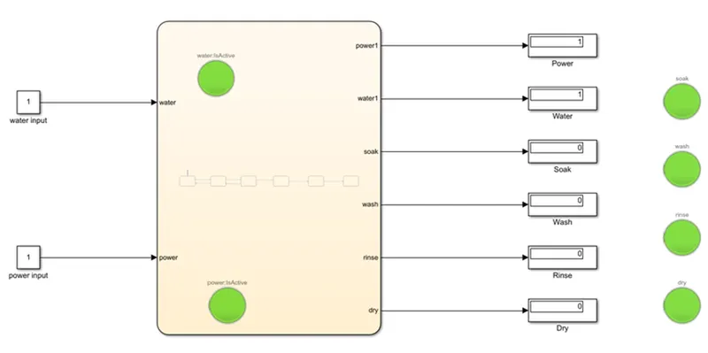
Once this is created the lamp blocks are connected respective to the corresponding blocks where two constants water and power supply is connected, once we give input to power and not to the water the lamp will indicate green light only to the power source lamped and once the water is given power source without the power supply only water lamp will indicate green color, when both water and power suplly is given input the lamp will indicate green color and dryer block which is end process will also turn on LED. Main program blocks are shown below.
Output:
- When Power & Water supply is 0, Output is 0
- When Power is 1 & Water supply is 0, Output is 0
- When Power is 0 & Water supply is 1, Output is 0
- When Power & Water supply is 1, Output is 1
2. Make a Simulink chart for the “Gear shift” logic as per below conditions:
Speed Range(kmph) Gear
0 to 15 1
16 to 25 2
26 to 40 3
41 to 60 4
Above 61 5
Give speed input while the simulation is running & display the gear number.
To calculate the 'Gear Shift' logic in SIMULINK blocks,
Constant block is connected to the slider gain block which is used to adjust or set the speed limit of the gear accordingly, which is connected to the chart where sub-system blocks are added as below shown image, where Gear1 to Gear5 is connected with four input speeds as Gear1 with 15kmph, Gear2 with 25kmph, Gear3 with 40kmph, Gear4 with 60kmph.

In the above figure the sub-system is connected to the chart which is connected to display block where the speed control is controlled by slider gain where the display shows which gear to be used according to the speed.
Output:
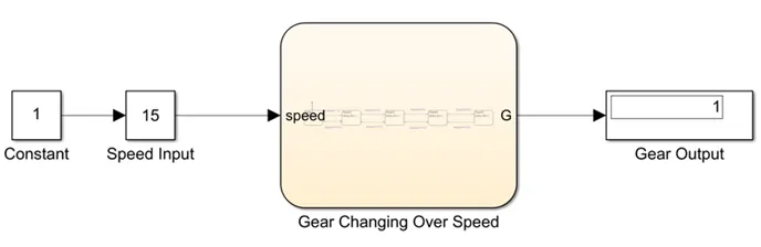
The output is given for the 1st Gear is as below:
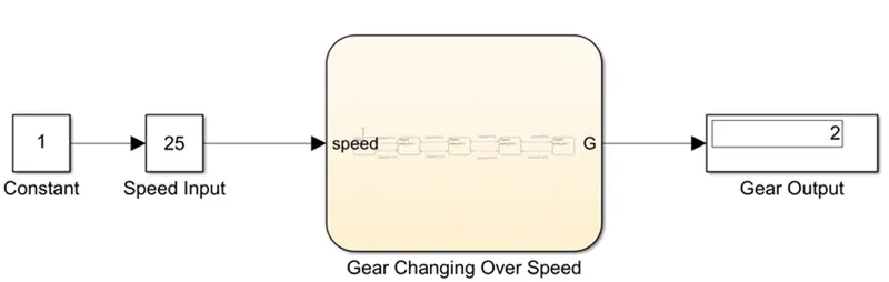
The output is given for the 2nd Gear is as below:
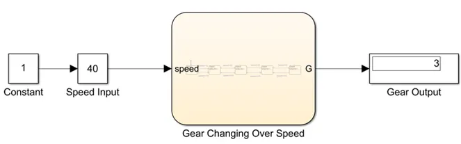
The output is given for the 3rd Gear is as below:
The output is given for the 4th Gear is as below:
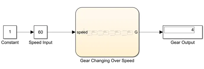
The output is given for the 5th Gear is as below:
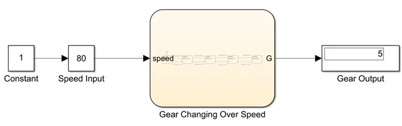
The above output results shows which gear to be used according to the speed.
Result:
The above procedure is used to run and simulate the washing machine according to the given condition and also to calculate the gear logic according to the speed input using SIMULINK.