Week - 4
AIM :
1) Implement control logic of a “washing machine” using Stateflow as per the given sequence.
2) To make a Simulink chart for the “Gear shift” logic as per given conditions.
Now let us solve the AIM No. 1 first.
1) Implant Control logic of a Washing Machine:
In the mentioned challenge we have to use the stateflow feature of simulink to implement the control the control logic of washing machine as per given data. Before that in we need to know two things.
Here we need to understand one term which has been mentioned in the question which is Stateflow.
Stateflow:
Stateflow provides the graphical language that includes state transition digrams, state transition tables, flow charts, truth tables & state transition tables.
Stateflow can also be used to describe how matlab algorithms & simulink models react to input signals, events, & time based conditions.
Stateflow also enables to design & develop supervisory control, fault management, task scheduling, user interfaces, communication protocols & hybrid systems.
With the use of stateflow we can model combinatorial & sequential decision logic that can be simulated as a block within a simulink model or executed as an object in the Matlab.
The Graphical animation enables us to analyze & debug the logic while it is executing. Run-time & Edit-time ensures design consistancy & completeness before implementation.
Control Logic:
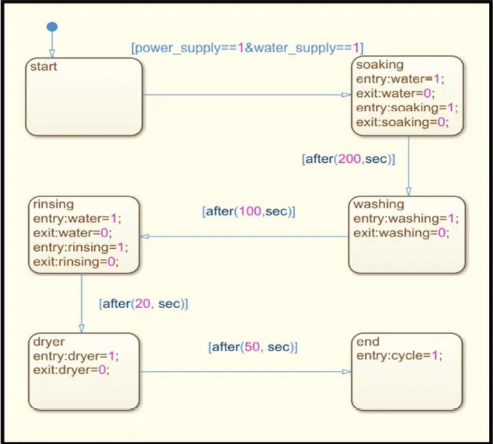
Description:
Here one thing is considered that we have continuous power & water supply when the simulation is running. The system only operates in given condition.
- In the above diagram the intial or we can say starting state is created with the two transition conditions, First is the power supply = 1 & second is water supply = 1. It means that both the water & power supply are on.
- The state which comes second is soaking. In soaking state the supply of water is required. So the water supply is given & after completion of soaking the supply is stopped. The condition is given in the above logic & the time duration given for this phase is 200s with the help of transition condition.
- The next stage is washing in this state only washing is done with the water available in the washing machine. This process consumes 100s time as per the given transition condition. After washing water is drained from the machine.
- The fourth stage is rinsing & in this state repeated washing is done so the continuous water supply is essential. The water supply gets off after 20s.
- The fifth state is dryer in which the clothes will be dried in 50s of time as given in the transition condition. After completion of this process dryer gets off.
Symbols :
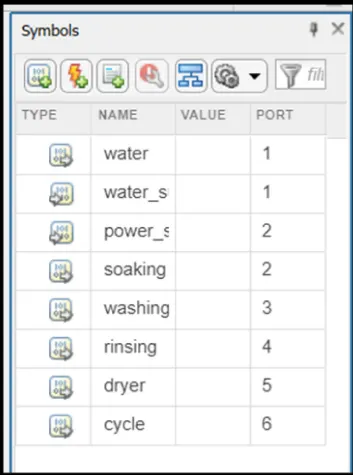
Here we need to understand what are the input & output in our system.
Here Input data is Water & Power supply.
And output data is water & the processes like soaking, washing, rinsing & dryer.
Washing Machine Model :
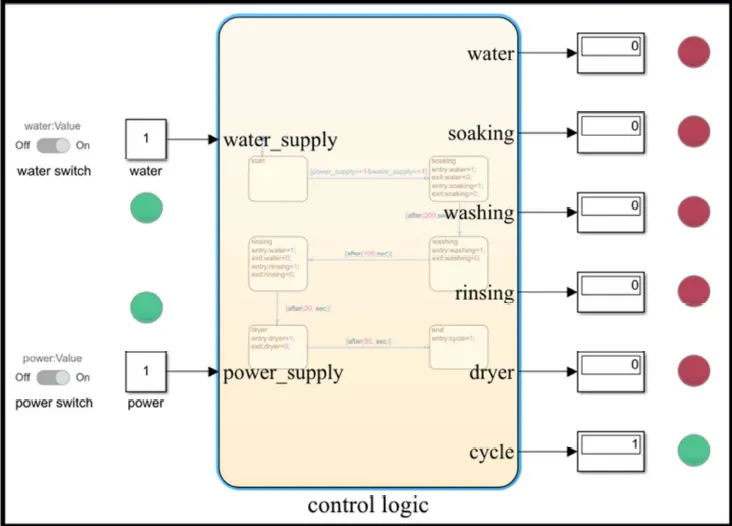
Now lets understand about the above control logic.
- In the given model stateflow chart is used to create the control logic for the washing machine.Twwo switches are used here to operate the power & water supply.
- The lamps are used here for the on/off indication of the state of the supply & process. These lamps & switches are connected to the constant block & constant block is connected to the control logic.
- All the process parts have connection with the display & the display is connected with the lamp.
- After completion of all process the light of cycle would lit in green. The simulation has been ran for 400s.
Now lets move to the second aim.
2) To make a Simulink chart for the “Gear shift” logic as per given conditions.
Control Logic :
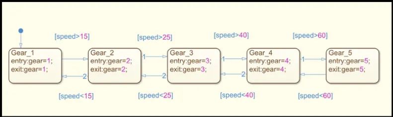
As per the condition given for gear shifting in the question we have created the stateflow diagram with help transition to give condition with respect to speed.
Symbols :
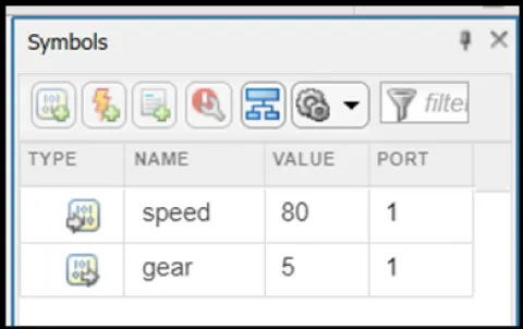
Here Input data is Speed.
And output data is Gear.
Model of Gear Shifting :
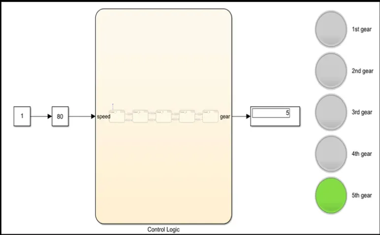
In the model given above we have used the slider gain block for the variable speed & connect to connect to the control block. Also display block is connected to the control logic to see that which gear is running & also the lamps are used to for the better track of the process.