Week -2
AIM :
1) To make a simulink model of doorbell using the solenoid block.
2) To make a simulink model by using a thermister to sense the temperature of a heater & turn on & off the fan by using the given conditions.
Here in this assignment two terms are very important to understand which are Solenoid & Thermister.
Solenoid :
A solenoid is a type of electromagnet formed by a helical coil of wire whose length is substantially greater than its diameter which generates a controlled magnetic field. The coil can produce a uniform magnetic field in a volume of space when an electric current is passed through it. The term solenoid was coined in 1823 by André-Marie Ampère.
The helical coil of a solenoid does not necessarily need to revolve around a straight-line axis; for example, William Sturgeon's electromagnet of 1824 consisted of a solenoid bent into a horseshoe shape (not unlike an arc spring).
Solenoids provide magnetic focusing of electrons in vacuums, notably in television camera tubes such as vidicons and image orthicons. Electrons take helical paths within the magnetic field. These solenoids, focus coils, surround nearly the whole length of the tube.
Thermistor :
A thermistor is a type of resistor whose resistance is strongly dependent on temperature, more so than in standard resistors. The word thermistor is a portmanteau of thermal and resistor.
Thermistors are divided based on their conduction model. Negative Temperature Coefficient (NTC) thermistors have less resistance at higher temperatures, while Positive Temperature Coefficient (PTC) thermistors have more resistance at higher temperatures. Hence, a PTC thermistor's resistance is directly proportional to temperature.
Now lets proceed towards our first AIM.
1) Preparation of Simulink model of doorbell using Solenoid:
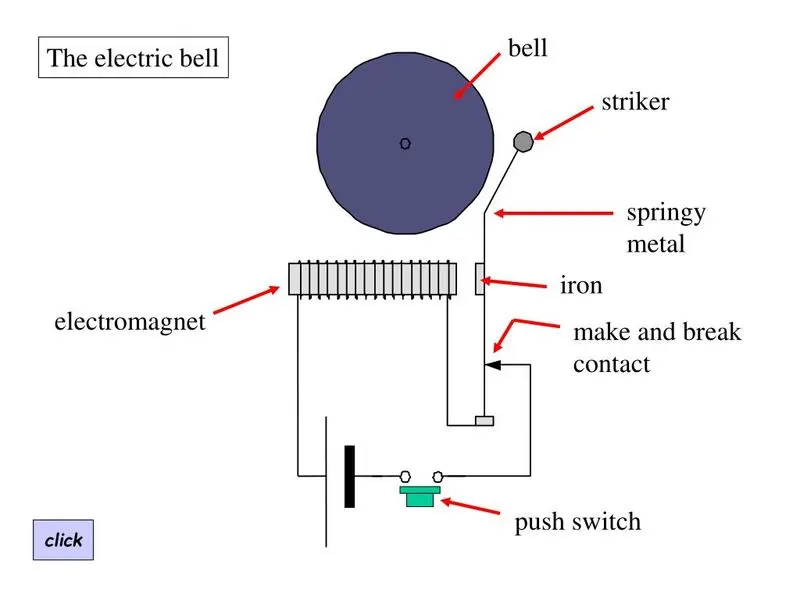
Above image is a simple circuit representation of an electric bell. By observing this diagram we can easily understand how the electric bell actually works.
Now lets move towards the simulink model for the same.
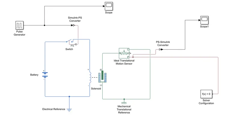
Explanation :
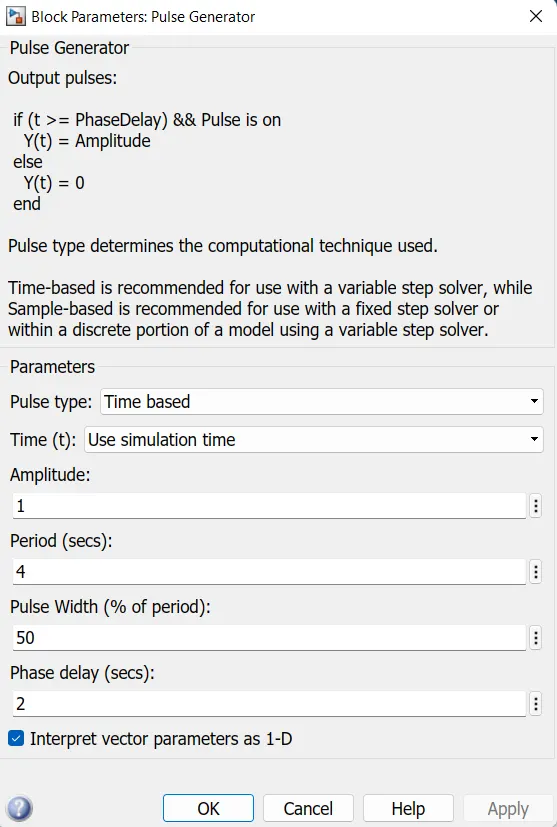
- First of all the pulse generator block is used to give signal inputs like amplitude, pulse width, period & phase delay to determine the shape of the output length. Here Scope is used to visualize the graph of wavelength.
- Then the Simulink-PS converter is used to convert input of the signal to physical system & send to the switch block.
- To complete the circuit Battery, Switch & Solenoid block are attached appropriately together.
- Also Electric reference is used as a ground. After that all the systems are connected in the series. The solver configuration block is used to specify the solver parameter.
- The mechanical part of solenoid is connected to an ideal translational motion sensor because the motion of the clapper is translational & for ground the mechanical translational reference is used.
- Now scope is connected to an ideal translational motion sensor to see the output graph of the plunger motion.
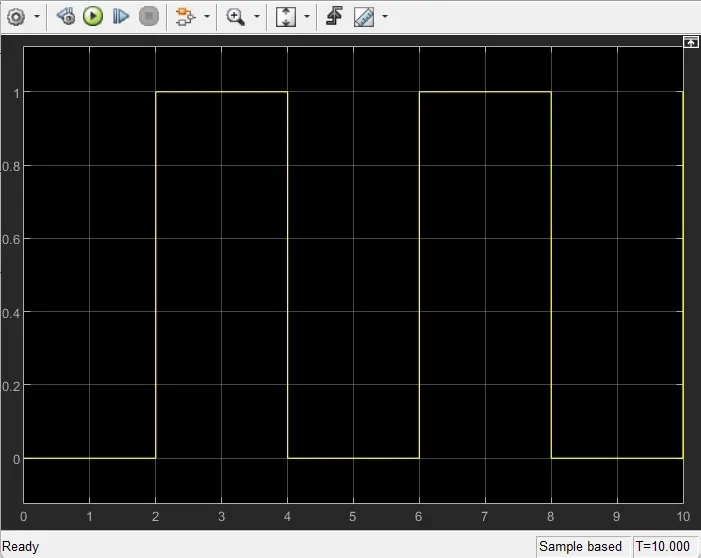
- Both the graphs which we get as an ouptput are given below.
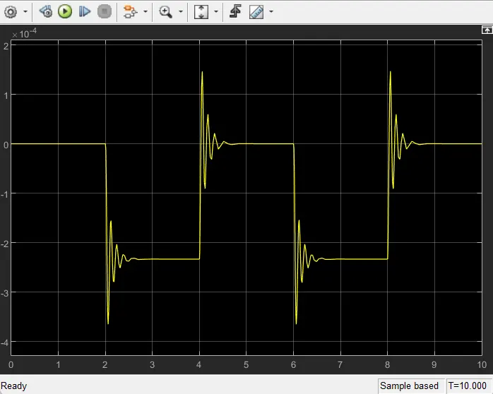
Now lets move towards the AIM-2.
2) To make a simulink model by using a thermister to sense the temperature of a heater & turn on & off the fan by using the given conditions:
First of all lets understand a bit about Thermister.
Thermistor :
A Thermistor is a type of resistor whose resistance is strongly dependent on temperature, more so than in standard resistors. The word thermistor is a portmanteau of thermal and resistor.
Thermistors are divided based on their conduction model. Negative Temperature Coefficient (NTC) thermistors have less resistance at higher temperatures, while Positive Temperature Coefficient (PTC) thermistors have more resistance temperatures. Hence, a PTC thermistor's resistance is directly proportional to temperature.
Model :
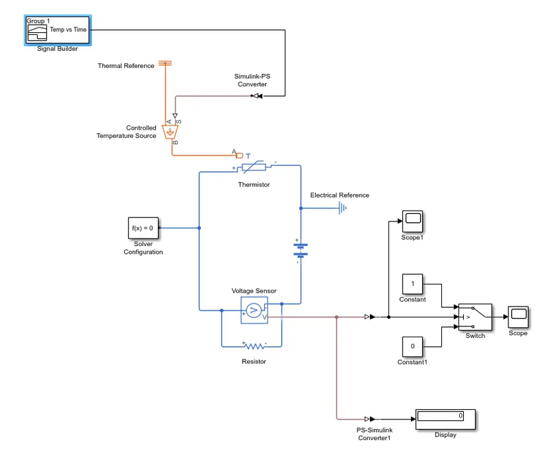
Now lets understand a it about the blocks which are used to generate this simulink model.
1) Signal Builder :
The signal builder block is used to generate interchangeable groups of piecewise linear signal source & use them in a model. You can quickly switch the signal groups into & out of a model to facilitate the testing.
2) Simulink-PS Converter :
This block converts input simulink signal into a physical signal. This block is used to connect simulink sources or other simulink blocks to the input of the simscape physical network.
3) Thermal Referance :
The thermal referance block represents a thermal reference point i.e. a point with an absolute zero temperature with respect to which all the temperature in the system are determined.
4) Controlled Temperature Source :
This block reperesents an ideal source of thermal energy which is powerful enough to maintain specified temperature difference across the source regardless of the heat flow consumed by the system.
5) Thermistor :
This block reperesents an NTC thermistor which senses the temperature with respect to time.
6) Voltage Sensor :
The voltage sensor block represents the device that converts the voltage measured between two points of the electrical circuit into a physical signal proprtional to the voltage.
7) Battery :
This block implements a generic dynamic model that represents the most popular types of rechargeable batteries.
8) Electrical Reference :
This block represents electrical ground. Electric conserving ports of all the blocks that are directly connected to the ground must be connected to an electrical reference block. A model with electrical elements must contain at least one electrical reference block.
9) Solver Configuration :
Here each physical network is represented by a connected simscape block diagram requires solver setting information for simulation. The solver configuration block specifies the solver parameters that your model needs before you can begin simulation.
10) PS-Simulink Converter :
The PS-Simulink converter block converts a physical signal into a simulink output signal. Use this block to connect outputs of a simscape physical network to simulink scopes or other simulink blocks.
11) Switch :
The switch block passes through the first input or the third input signal based on the value of the second input. The first & third inputs are data input. The second input is control input. Specify the condition under which the block passes the first input by using the criteria for passing first input & threshold parameter.
12) Constant :
The constant block generates a real or complex constant value signal. Use this block to provide a constant signal input.
13) Display :
The display block shows the value of the output data. You can specify the frequency of the display. For numeric output data , you can also specify the format of display.
14) Scope :
Display signals generated during simulation in simple word display graph with respect to time.
Model Explaination with outputs :
Now lets discuss about the model & its outputs.
1) First of all we add thermistor block. The port is connected with a controlled temperature source block. The block one port is connected to thermal reference & another port is connected to the converter.
2) The temperature difference is set by the physical signal port which is connected to signal builder by using Simulink-PS converter. This converter has been used to get the physical signal to further provide it to temperature source input. The input signal which is given to signal builder is the simulink signal.
3) As per the given condition in the question in signal builder we have created an input signal for the system.
- 0-10 sec - temperature is 293.15 K (20°C)
- 10-30 sec - temperature is 300.15 K (27°C)
- 30-50 sec - temperature is 296.15 K (23°C)
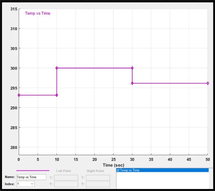
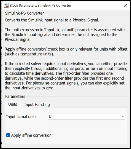
4) Here the temperature is converted in Kelvin as there is no option in the signal converter to add the temperature in degree celcius. But there is second option of applying affine conversion, then feed the input signal data in Kelvin. One more thing to consider that selected solver requires input derivatives that we can either provide them explicitly through the additional signal port or can turn on input filtering to calculate time derivatives.
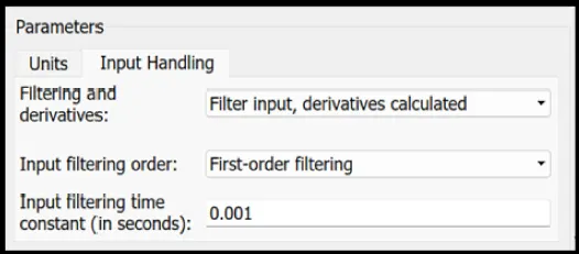
5) Battery & voltage sensor are then connected in series & resistor connected in parallel to voltage sensor. The solver configuration is also used to specify the solver parameter. The electric reference is also used to ground the electric system.
6) Then voltage sensor is connected with the switch to control the fan with the help of PS-Simulink converter to convert the signal in simulink input. Then the Scope is used to decide threshold value of switch. Then the display is connected to see the last simulation value so that we can decide our threshold value with the help of PS-Simulink converter.
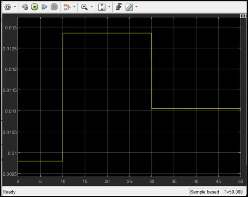
7) In the switch decided threshold value. If the temperature is above the threshold limit, then it gave '1' as output which means fan switch on & if the temperature is below the threshold limit, then '0' is used as output which means fan is switched off.
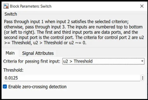
8) At the end of the system scope is connected to see output for fan on or off. Then we run the simulation for 50 seconds because we have taken time limit in signal builder as 50 sec. So, we can get the following output.
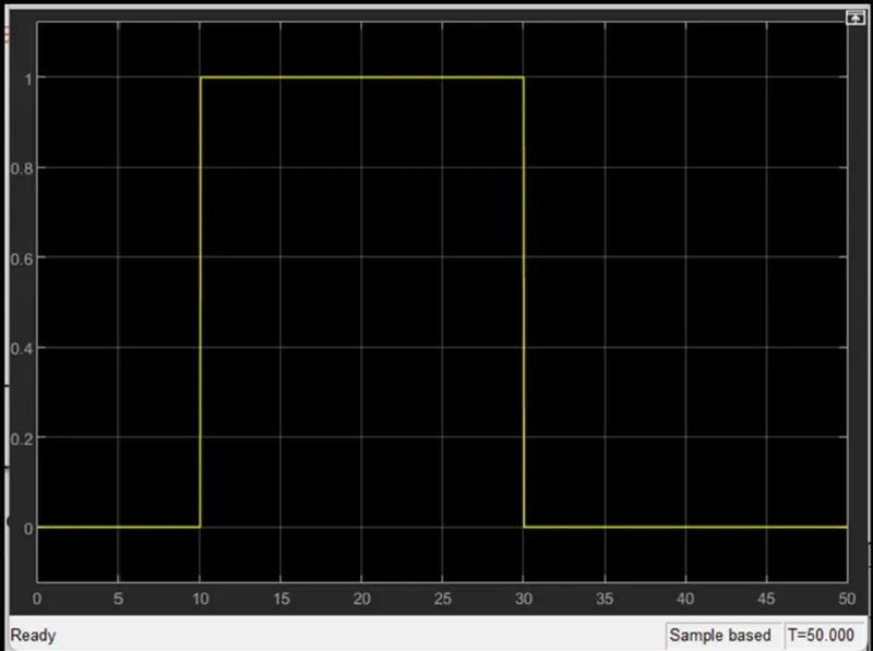
In the above graph it is clearly visible that from 0-10 sec signal is 0 because in this time the temperature was 20°C which is below 25°C that means fan is switched off. After that from 10-30 sec signal is 1 because at that time the temperature was 27°C which is above 25°C that means fan is switched on. At final stage from 30-50 sec signal is 0 because at that time temperature was 23°C which is below 25°C that means fan was switched off.
Conclusion :
From the received outputs we can conclude that our simulink model for solenoid operated heaters gives correct output & satisfies all input conditions.