Week - 4
- If the power supply is available, the system gets activated
- If the Water supply is not available, stop the process & indicate through LED
- Soaking time should be 200s followed by Washing time of 100s.
- Then rinsing happens for the next 20s & dryer runs for 50s
After all the processes have been completed turn on the finished LED
- Soaking/Prewash - The prewash step includes filling the washing machine's tub with water and mixing in the detergent.
- Washing - During the wash cycle, the machine uses agitation to mix the water and detergent and move the clothing around the tub--and against other clothing--to clean the load.
- Rinsing - Rinsing the load is usually a multi-step procedure. First, the soapy water must be spun from the clothing and wash tub. During the latter minutes of the purging, fresh water is sprayed into the tub to rinse the clothing.
- Drying/Spinning - Spinning is necessary for wringing the clothing and getting it as dry as possible before the end of the wash.
- Slider Switch - The Slider Switch block toggles the value of the connected block parameter between two values during simulation. For example, you can connect the Slider Switch block to a Switch block in your model and change its state during simulation.
- Constant - Output the constant specified by the 'Constant value' parameter. If 'Constant value' is a vector and 'Interpret vector parameters as 1-D' is on, treat the constant value as a 1-D array. Otherwise, output a matrix with the same dimensions as the constant value.
- Lamp - The Lamp block displays a color that indicates the value of the connected signal. To configure the Lamp block to provide the information you need during simulation, specify one or more states, which pair a signal value with a color for the Lamp block to display.
- Chart - The Chart block is a graphical representation of a finite state machine based on a state transition diagram. In a Stateflow® chart, states and transitions form the basic building blocks of a sequential logic system. States correspond to operating modes and transitions represent pathways between states.
- Display - Display input values. If the incoming signal is of a type string, the 'Numeric display format' parameter selection does not affect the display of the string.
Model:-
Below is the control logic of a “washing machine” using Stateflow as per sequence in Aim.
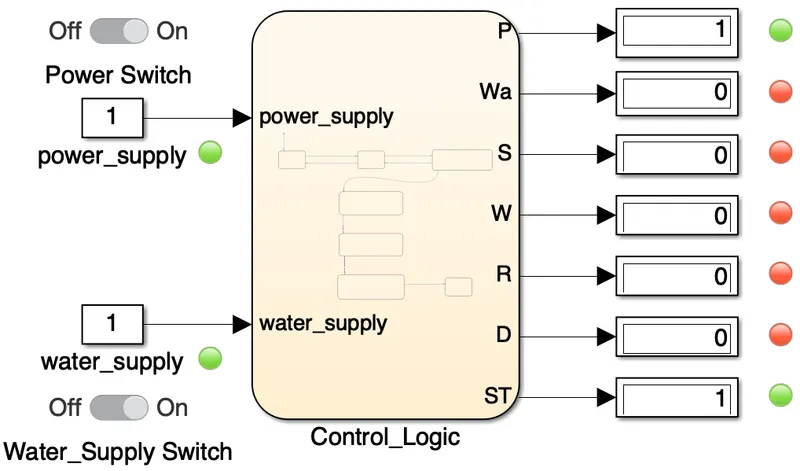
- Slider switches are connected to the power switch and water supply switch. As an input for the control logic constant blocks is used for power supply and water supply.
- 2 Lamp blocks are connected with the power supply and water supply. In case the slider switches are on for the power supply and water supply the lamp will show green light and in case the switches are off lamp will reflect red light.
- Control logic is implemented in the chart block.
- 7 Display blocks are used for the outputs from the chart block. Display blocks are used to indicate whether a particular port/output or process is active or inactive. In case it is active display block will reflect as 1 if not 0.
- Same way lamp blocks are used and are connected with the displays. The lamp will indicate red in case the display is 0 and will be green in case the display is 1.
- From the model, it can be seen that the 1st and the last lamp reflect a green color as the power is still on so the lamp connected to the display of the power_supply (P) is active and for the last state which is the stop state (ST) is also active because as the processes end so as the state active and hence the display is active and lamp indicating as a green color for the active display.
Stateflow -
Below is the Stateflow created for the processes of the washing machine.
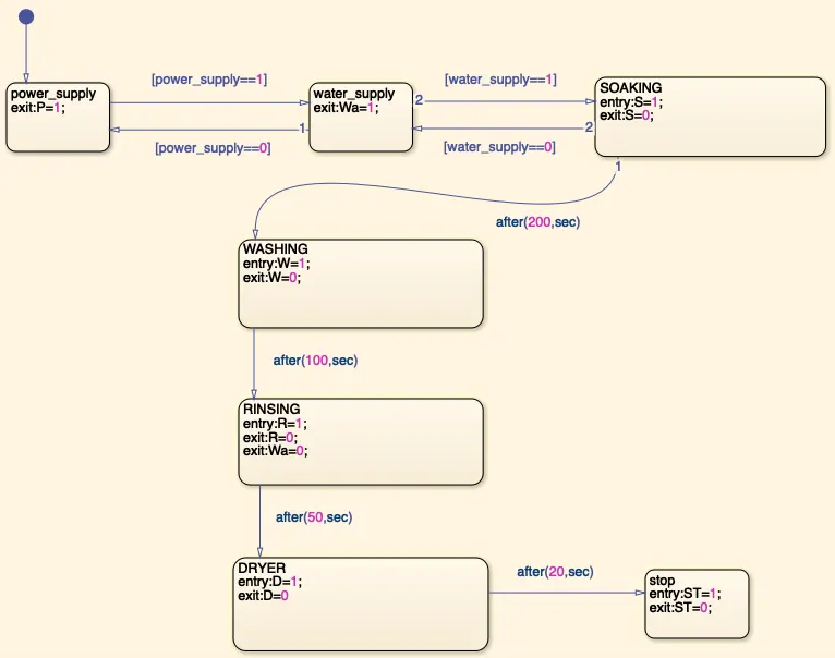
- Different blocks are used for different states where power_supply is on throughout the states and water_supply is on till the rinsing state.
- There are conditions given for the power_supply state and water_supply state that if the states are inactive then the transition will be reversed and will not proceed any further.
- Every process states are active for the given time through transition and then inactive.
- In the rinsing state, water_supply is made inactive as there is no requirement going further.
- The stop state is the end state of the process.
Stateflow Configuration -
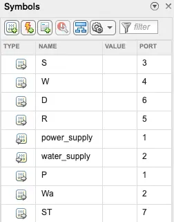
Below is the configuration for the washing machine Stateflow where the type is specified for each state as either input or output. Can be any other type depending on the Stateflow condition. Names are used as letters indicating particular states.
Lamp -
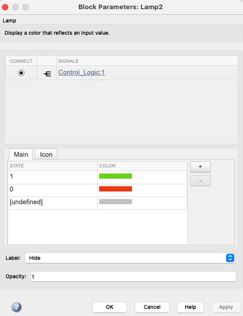
Below is the configuration of a lamp where a signal is connected to control logic:1 which is the display block of the output1 of the Stateflow. In case the state is 1 color will reflect as green and if the state is 0 then the color is red.
Result:-
As a result, a Simulink model of the control logic of the washing machine using Stateflow is created. In this model the stop time selected is infinity. While running the model, sequences from the Aim can be seen functioning.
Aim:- 2. Make a Simulink chart for the “Gear shift” logic as per the below conditions:
Speed Range(kmph) Gear
0 to 15 1
16 to 25 2
26 to 40 3
41 to 60 4
Above 61 5
Give speed input while the simulation is running & display the gear number.
Theory:-
In general, the gearbox is a power transfer system whose function is to distribute engine power to other engine parts. The goal is that these components can move either in the form of shifts or rotations. The gearbox can also be used to adjust the power or torque of the rotating motor, and also change the power of the rotating motor to be greater.
The working principle of the gearbox is to transmit the power generated by the engine rotation to other components in the engine so that these components can move.
The process of transferring power begins with the axle and wheel receiving a certain force that must be produced with large rotating power. The rotary power is sometimes very high, but other times it can decrease. Well, the role of the gearbox is to adjust or regulate the power so that the power can remain appropriate and be channeled optimally.
Blocks:-
- Airspeed Indicator - The Airspeed Indicator block displays measurements for aircraft airspeed in knots.
- Slider - The Slider block tunes the value of the connected block parameter during simulation. For example, you can connect the Slider block to a Gain block in your model and adjust its value during simulation. You can modify the range of the Slider block's scale to fit your data.
Model:-
Below is the Simulink model for the “Gear shift” logic as per the given conditions from the Aim.
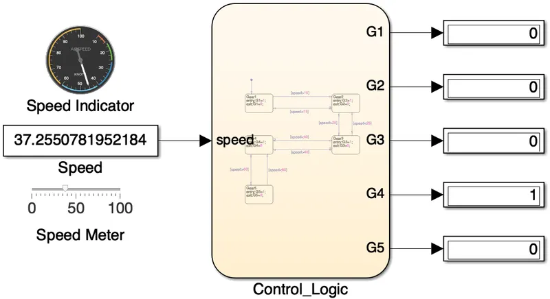
- Speed is used as input for the control logic.
- A speed indicator is used to show the speed in the analog form which is connected to the constant block which is the speed block.
- Speed can be changed through a speed meter while the simulation is running which is also connected with the speed/constant block. Based on which constant block will reflect the speed with the speed indicator.
- Stateflow of the control logic is built in the chart block.
- For every output of the Stateflow, a display block is connected to identify which output is active or inactive. In case the display block gets an input it will reflect as 1 if not 0 which also means that the particular Stateflow output is active or inactive.
- In the above model, it is seen that Gear4 (G4) is active and the rest are inactive which indicates as per the given speed the current active gear is 4thgear.
Stateflow -
Below is the Stateflow for the Gear shift logic as per the given speed conditions.
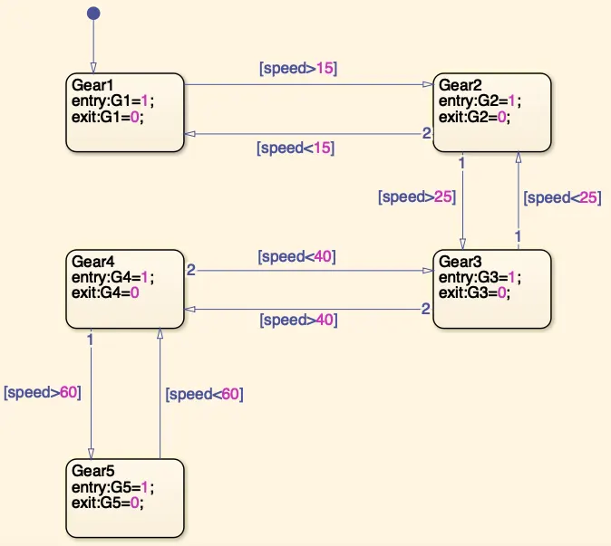
- Different states are made for different Gears where the main thing is that for every state transition a speed condition is determined.
- Every state of the Gear has some speed condition where if the speed is more than that then the Gear state will shift to the appropriate one. In case the speed is lower then the Gear shift will be reversed to the one which follows that speed condition.
- In the above Stateflow if the speed is more than 15 then the gear will shift to the next Gear state which is Gear2 (G2) and in case the speed is lower than 15 then it'll be reversed.
- The above Simulink model has a total of 5 gears where Gear5 (G5) is the last Gear following the condition that is if the speed is more than 60.
Stateflow Configuration -
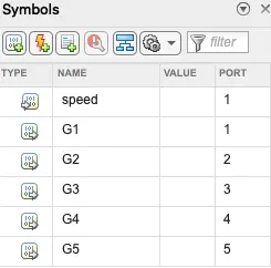
Following are the configuration of the Gear shift model speed is the input type and the rest are the outputs.
Speed Indicator -
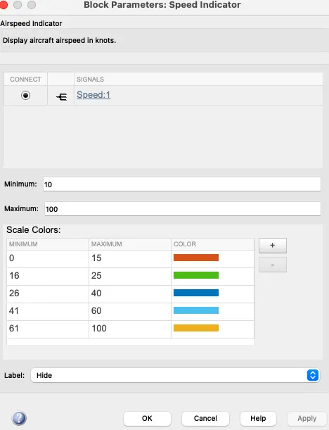
Changes can be made as per the model condition in the speed indicator and below are the configuration made for the Gear shift model.
Result:-
As a result, the above Simulink control logic Gear shift model is made using Stateflow. Stop time for the model is infinity where while the model is running speed can be changed through a speed meter and gear shift can be seen as per the required condition.