Week 4
WEEK 4: CHALLENGE
Aim
To check the geometrical errors in the given component, extract mid-surface and assign proper thickness to it and mesh the components as per the following quality criteria.
Sl.No Quality Criteria Value
1 Target/Average Length 1
2 Minimum Length 0.5
3 Maximum Length 3
4 Aspect 3
5 Warpage 15
6 Skewness 45
7 Jacobian 0.7
8 Minimum Quad Angle 45
9 Maximum Quad Angle 135
10 Minimum Tria Angle 30
11 Maximum Tria Angle 120
12 Tria Percentage 15
Procedure
The file “Bottle cap_updated.IGS” is imported into ANSA and then geometry clean up, mid-surface extraction, thickness assignment and meshing is done successively. The details of each of these steps are discussed below.
1. Geometry Clean up :
After importing the model, Geometry Clean-up is performed to remove unchecked faces, needle faces, cracks, collapsed cons and triple cons by removing the unnecessary cons and hot points and stitching the surfaces properly. This can be done using automatic "Fix" option or manually. Figure 1.1 shows the model after Geometry Cleanup.
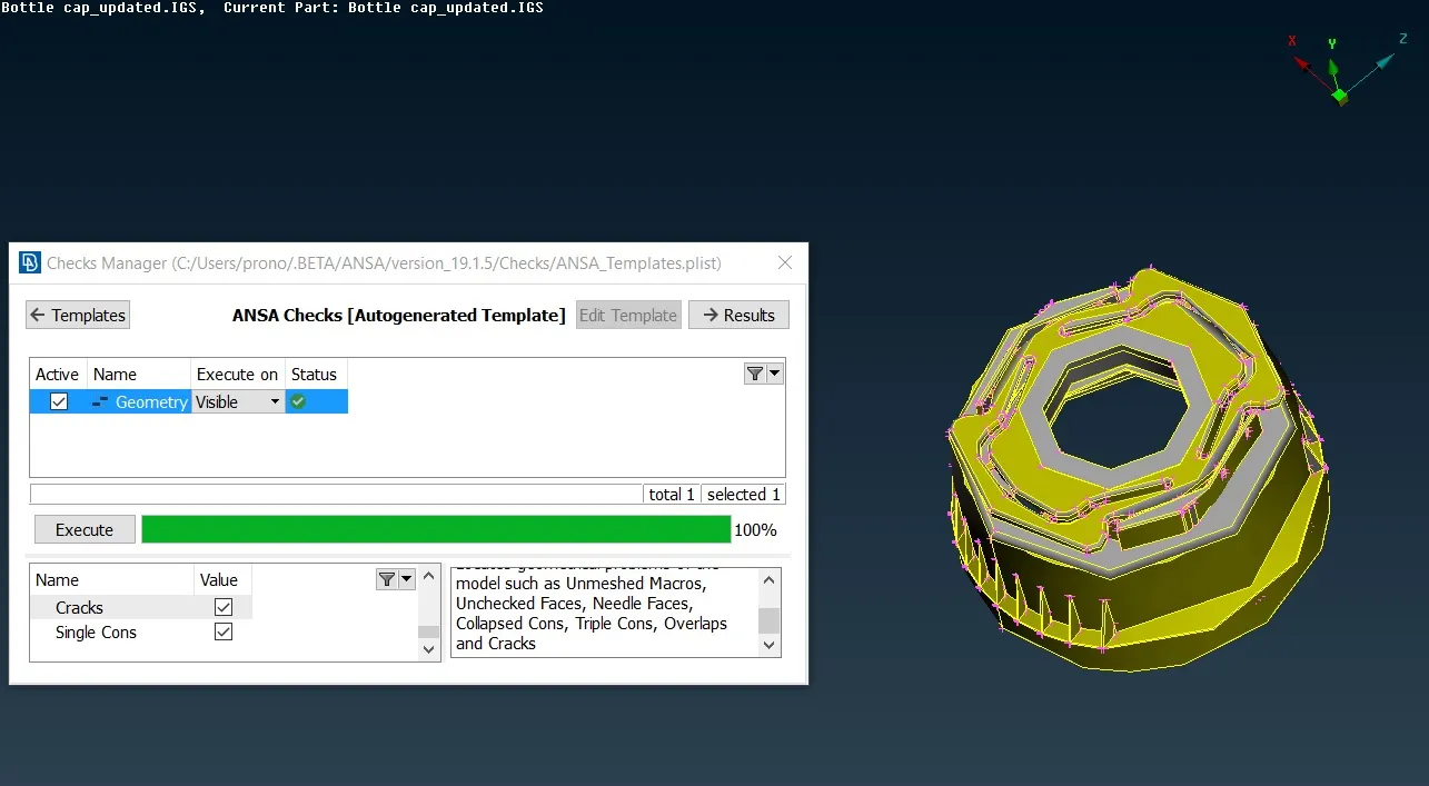
Figure 1.1 Model after Geometry Cleanup
2. Mid-Surface Extraction :
The assembly consists of two different parts as shown in Figure 2.1 and Figure 2.2. The mid-surface of these components as shown in Figure 2.3 are extracted using the manual offset, (Faces->Middle) option. For those features which have varying thickness like the internal threads and external ribs (Curve-> Middle, Project->Cons and Faces->New->Coons) are used to generate new faces.
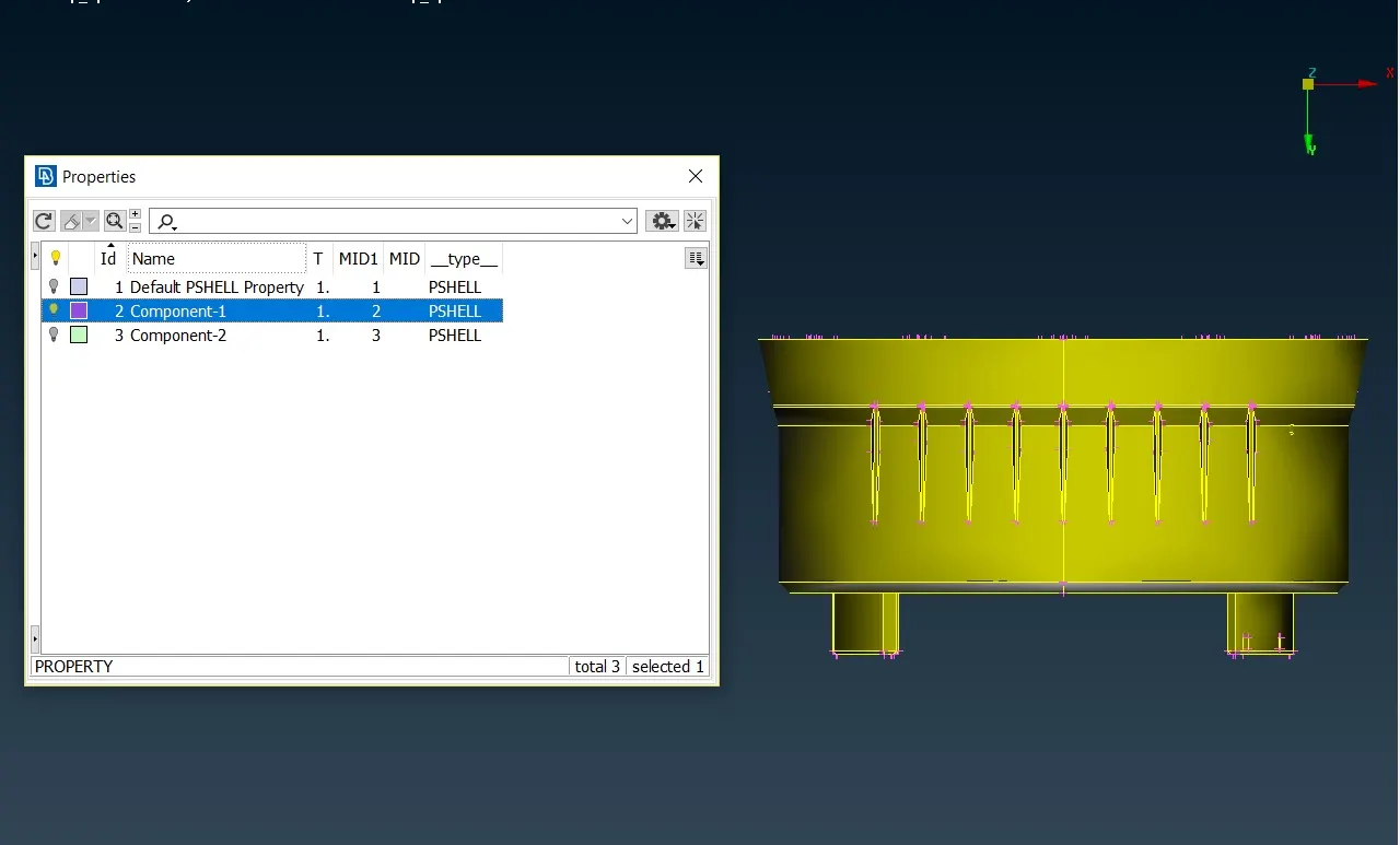
Figure 2.1 Component-1
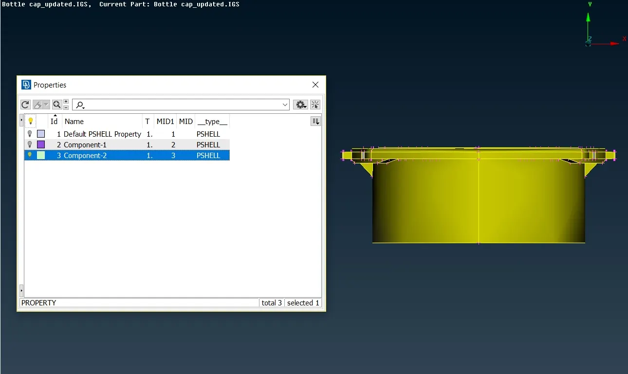
Figure 2.2 Component-2
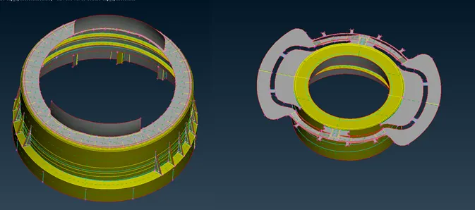
Figure 2.3 Mid Surface Extraction
The Component-1 has some internal symmetric features whose midsurface has been duplicated using the (Transform->Copy->Rotate) option as shown in Figure 2.4. The Rotate command reduces the time required for repetitive task which involves symmetric features. Before using the rotate command an axis of rotation is created using the two points created using (Points-> On COG) option.
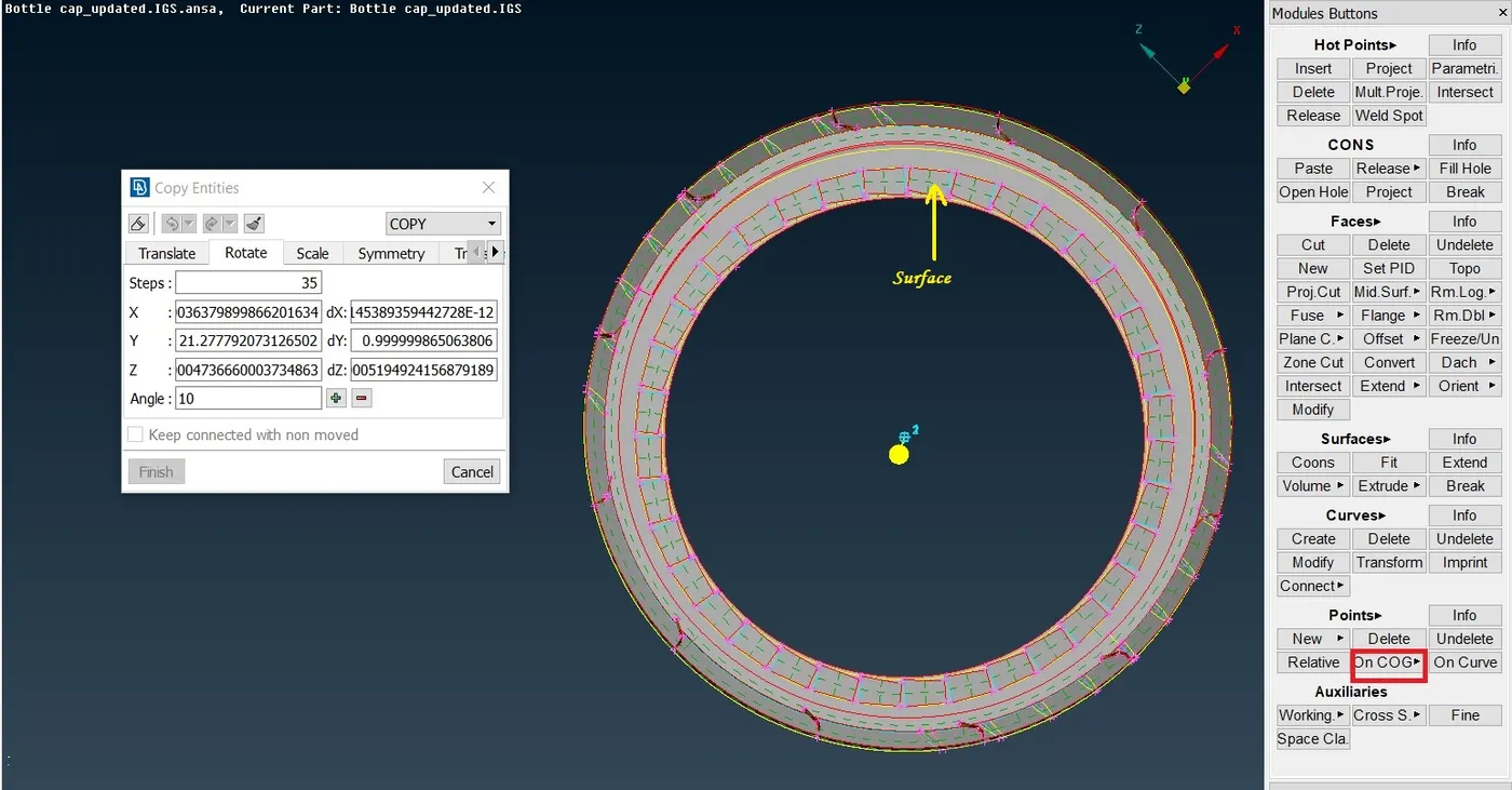
Figure 2.4 Rotate Command for Surface having symmetry
3. Meshing
Before meshing the midsurface of each components the perimeter length is set to target element length which in this case is 1 mm, the edge of the holes is slided parallel to surface and even number of edges is ensured in the holes using (Perimeters->Number) option. The top of the beads and fillets are also captured using the (Cut) option. The quality criteria is assigned in the Mesh Parameters and the faces are meshed using the (Best Mesh) option. For achieving a better mesh flow commands like (Num +/-, Shell Mesh-> Reconstruct/Smooth, Elements-> Split, Swap, Join) are used. After creating the mesh a separate PID is assigned to each of midsurface along with the thickness as shown in Figure 3.1
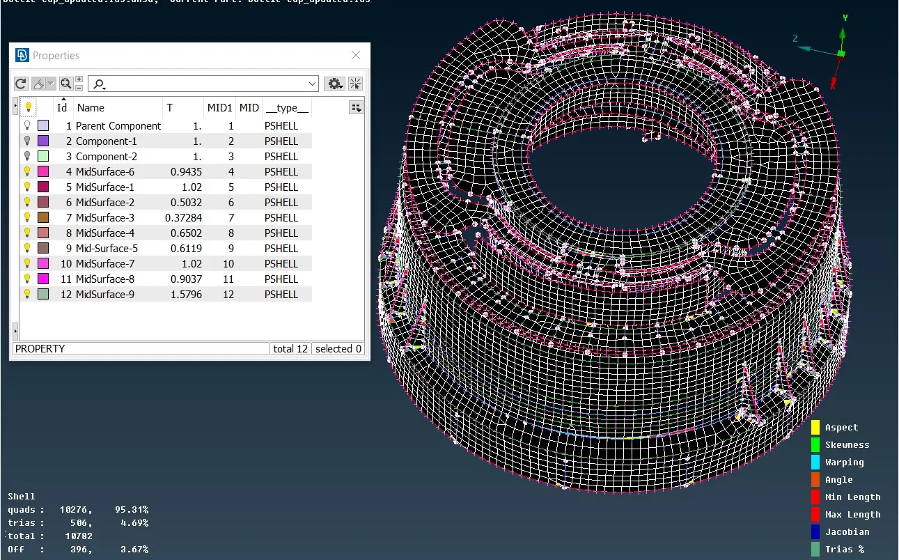
Figure 3.1 Meshed Model with Assigned Thickness
After meshing, the user defined macro lines are removed by using (Macro->Join option). Defeaturing of some parts of the model could not be done to achieve a better mesh flow and reduce the number of off elements as it will lead to geometric distortion. The extension and intersection of external and internal ribs with the parent component during midsurface generation lead to the creation of several triple cons in the model which could not be avoided.
The draw shell as solid option is activated in the last step as shown in Figure 3.2
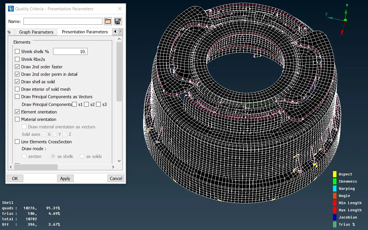
Figure 3.2 Conversion of 2D Mesh to 3D Mesh
Learning Outcome
1) A new command "Rotate" is used for the first time while doing this assignment.
2) Several commands to extract midsurface of the components like (face-> offset, middle), project->cons, face->extend, intersect has been used extensively while completing this work.
Conclusion
a) For avoiding tria elements in the perimeter adequate number of points must be present on the perimeter which can be adjusted using (Perimeter - Num+/- option)
b) Meshing should start from inner surface with more features and end on the outer periphery. This helps in achieving more quad elements while using (Shell- Reconstruct option).
c) Smooth Midsurface leads to better mesh flow and lesser element distortion.
d) Defeaturing leads to better element quality but distorts the model and feature lines gets supressed.