Week 3
WEEK 3: CHALLENGE
Aim
To check the geometrical errors in the given component, extract mid-surface and assign proper thickness to it and mesh the components as per the following quality criteria.
Sl.No Quality Criteria Value
1 Target/Average Length 5
2 Minimum Length 2
3 Maximum Length 7
4 Aspect 3
5 Warpage 15
6 Skewness 45
7 Jacobian 0.7
8 Minimum Quad Angle 45
9 Maximum Quad Angle 135
10 Minimum Tria Angle 30
11 Maximum Tria Angle 120
12 Tria Percentage 15
Procedure
The file “Hood model_1.stp” is imported into ANSA and then geometry clean up, mid-surface extraction, thickness assignment and meshing is done successively. The details of each of these steps are discussed below.
1. Geometry Clean up :
After importing the model, Geometry Clean-up is performed to remove unchecked faces, needle faces, cracks, collapsed cons and triple cons by removing the unnecessary cons and hot points and stitching the surfaces properly. Figure 1.1 shows the presence of triple cons in the model before geometry clean-up which has to be removed prior to generating the mid-surface.
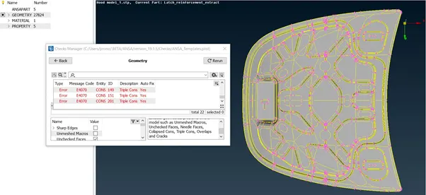
Figure 1.1 Model before Geometry Cleanup
The presence of triple cons which are to be removed from the model is shown in Figure 1.2
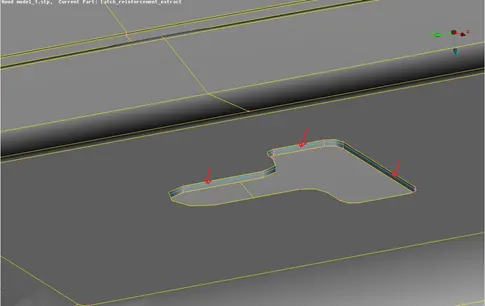
Figure 1.2 Triple Cons in the model
After removing all the triple cons and cracks from the model, the geometry becomes free from errors as shown in Figure 1.3 and is ready for middle surface extraction.
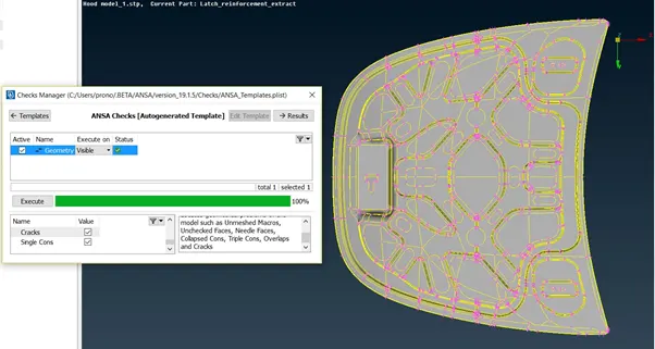
Figure 1.3 Model after Geometry Cleanup
2. Mid-Surface Extraction and Thickness Assignment :
The model consists of four different components whose mid-surface are extracted: outer hood, inner hood, latch and hinge. The mid-surface of all the components are extracted using the manual offset option and then separate PID is assigned to each of these surfaces along with the thickness as shown below.
2.1 Outer Hood Surface -
Figure 2.1 shows the midsurface and PID of outer hood surface with an assigned thickness value of 0.75 mm.
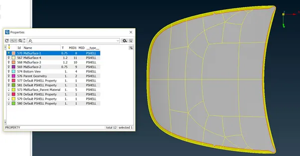
Figure 2.1 Outer Hood Surface
2.2 Inner Hood Surface
Figure 2.2 shows the midsurface and PID of inner hood surface with an assigned thickness value of 0.75 mm.
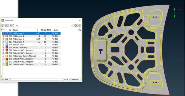
Figure 2.2 Outer Hood Surface
2.3 Latch Surface
Figure 2.3 shows the midsurface and PID of latch surface with an assigned thickness value of 1.2 mm.
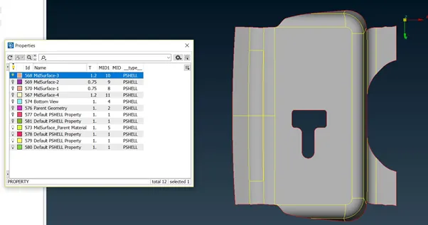
Figure 2.3 Latch Surface
2.4 Hinge Surface
Figure 2.4 shows the midsurface and PID of hinge surface with an assigned thickness value of 1.2 mm.
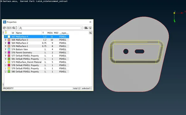
Figure 2.4 Hinge Surface
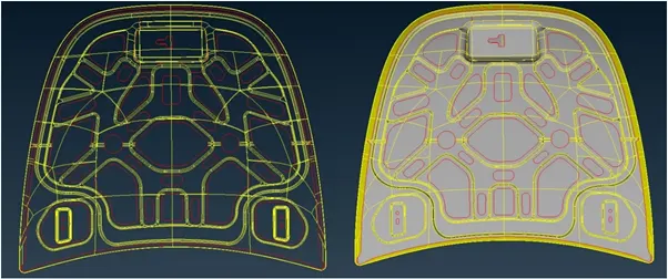
Figure 2.5 Mid-Surface of the entire assembly
3. Meshing
Before meshing the midsurface of each components the perimeter length is set to target element length which in this case is 5 mm, the edge of the holes is slided parallel to surface and even number of edges is ensured in the holes using (Perimeters->Number) option. The top of the beads and fillets are also captured using the (Cut) option. The quality criteria is assigned in the Mesh Parameters and the faces are meshed using the (Best Mesh) option. For achieving a better mesh flow commands like (Num +/-, Shell Mesh-> Reconstruct/Smooth, Elements-> Split, Swap, Join) are used. Figure 3.1, 3.2, 3.3, 3.4 shows the meshed midsurface of the four different components of the model.
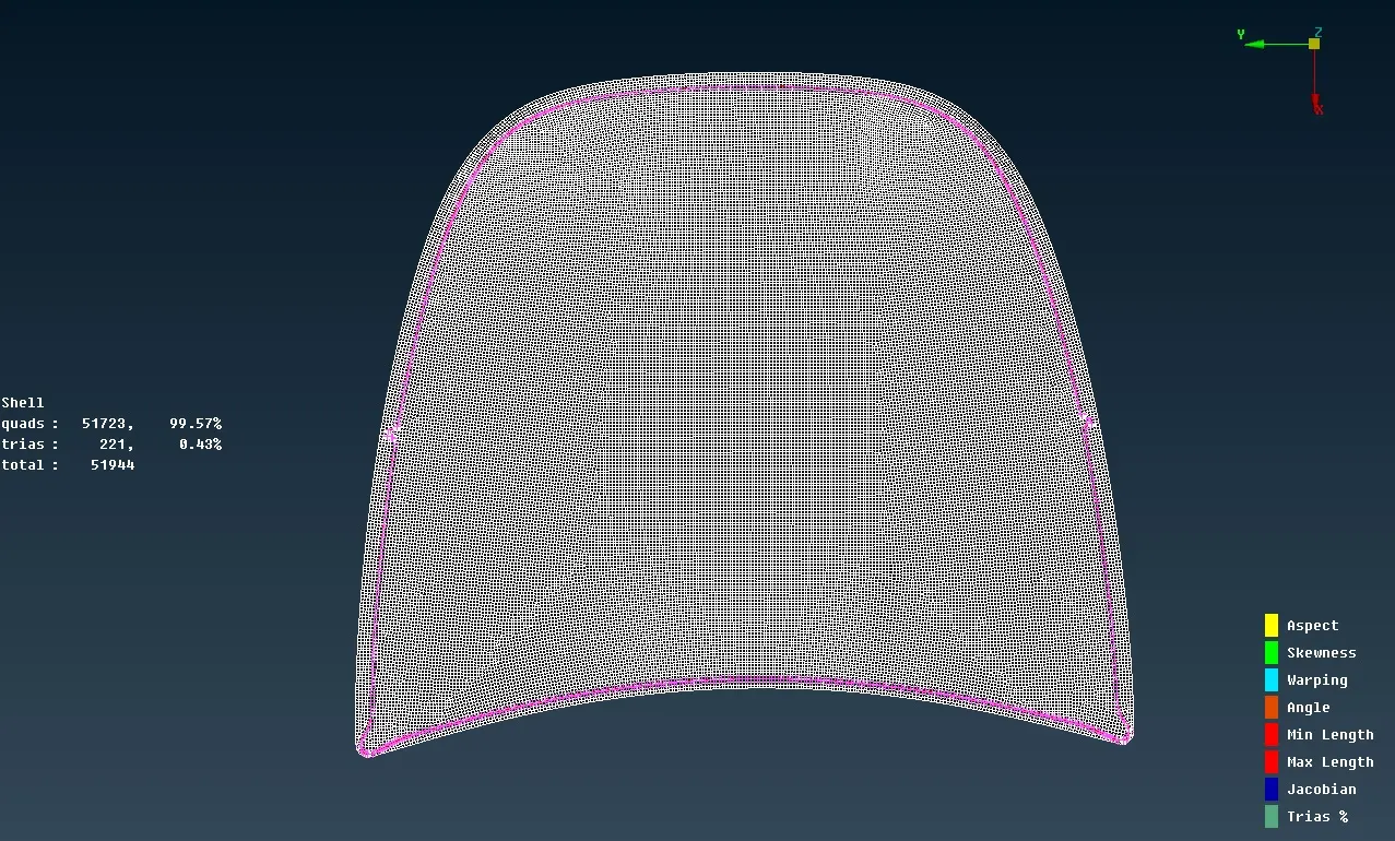
Figure 3.1 Meshed View of Outer Hood Surface
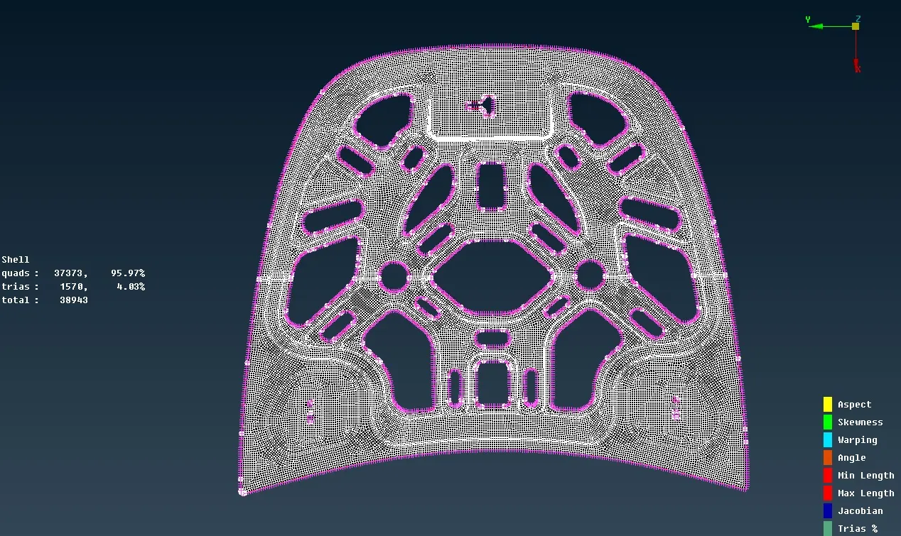
Figure 3.2 Meshed View of Inner Hood MidSurface
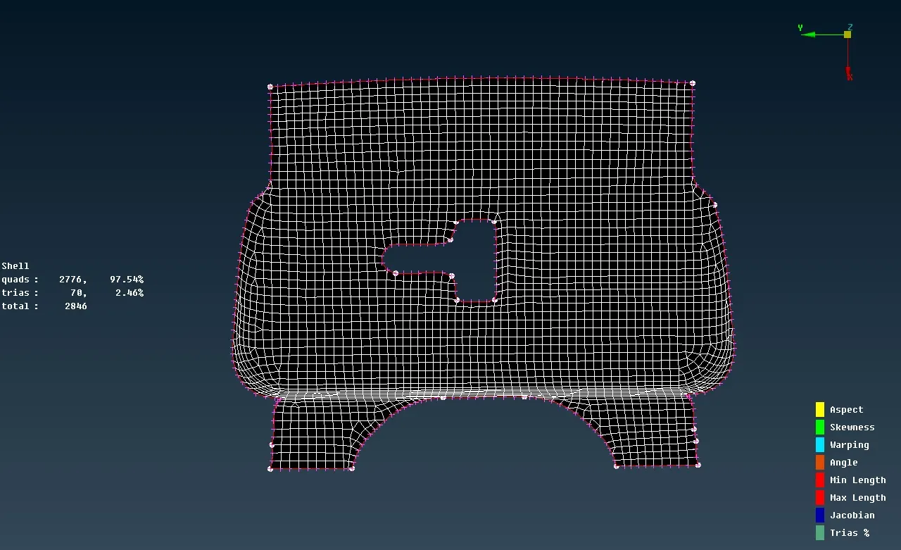
Figure 3.3 Meshed View of Latch MidSurface
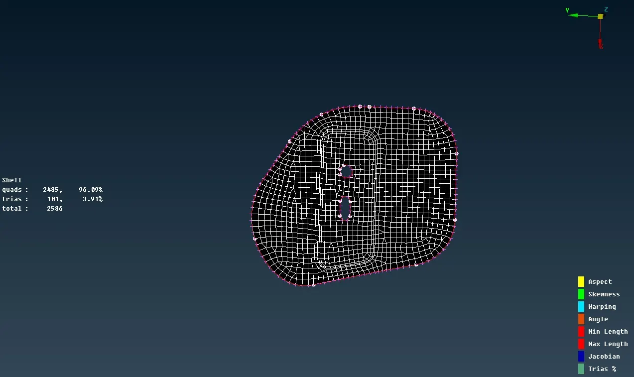
Figure 3.4 Meshed View of Hinge MidSurface
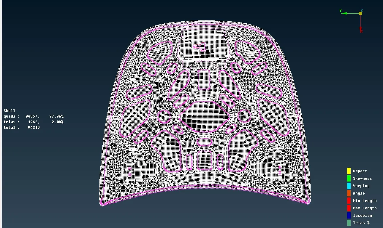
Figure 3.5 Meshed View of Hood Assembly MidSurface
After meshing the user defined macro lines are removed by using (Macro-Join option)
Learning Outcome
After completing this challenge I became familiar with the following acitivites in ANSA -
a) Geometry Cleanup using hotpoints, cons and topo.
b) The two methods of midsurface extraction, i.e manual offset method and by (MidSurface->Skin) option along with Material,PID and thickness assignment.
c) Prepare the midsurface for meshing by using (Cut,Slide) option, Defeaturing and how to set quality parameters.
d) Mesh Generation using Best Mesh and other options like (Macro - Cut and Join, Paste, Shell-Smooth and Reconstruct, Elements- Split and Join)
Conclusion
a) For structural analysis quad elements are more preferred than tria elements as tria elements are more stiff and meshing has to be performed in such a way that the number of tria elements are minimum and all the elements should pass the quality criteria.
b) For avoiding tria elements in the perimeter adequate number of points must be present on the perimeter which can be adjusted using (Perimeter - Num+/- option)
c) Meshing should start from inner surface with more features and end on the outer periphery. This helps in achieving more quad elements while using (Shell- Reconstruct option).