Week 6
WEEK 6: CHALLENGE
Aim
To implement the connections on rear door FE model
Procedure
The NASTRAN file “Rear-Door.nas” is imported into ANSA using File -> Input -> NASTRAN option. The model is already meshed and implementation of different connections is to be done in the NASTRAN deck. The following steps are performed to complete the challenge.
1. Seperate PID for Components:
Initially Default Shell Property for the complete model is assigned in PID. For better visualization and selection of parts while assigning connections seperate PID for different components is created as shown in Figure 1.1
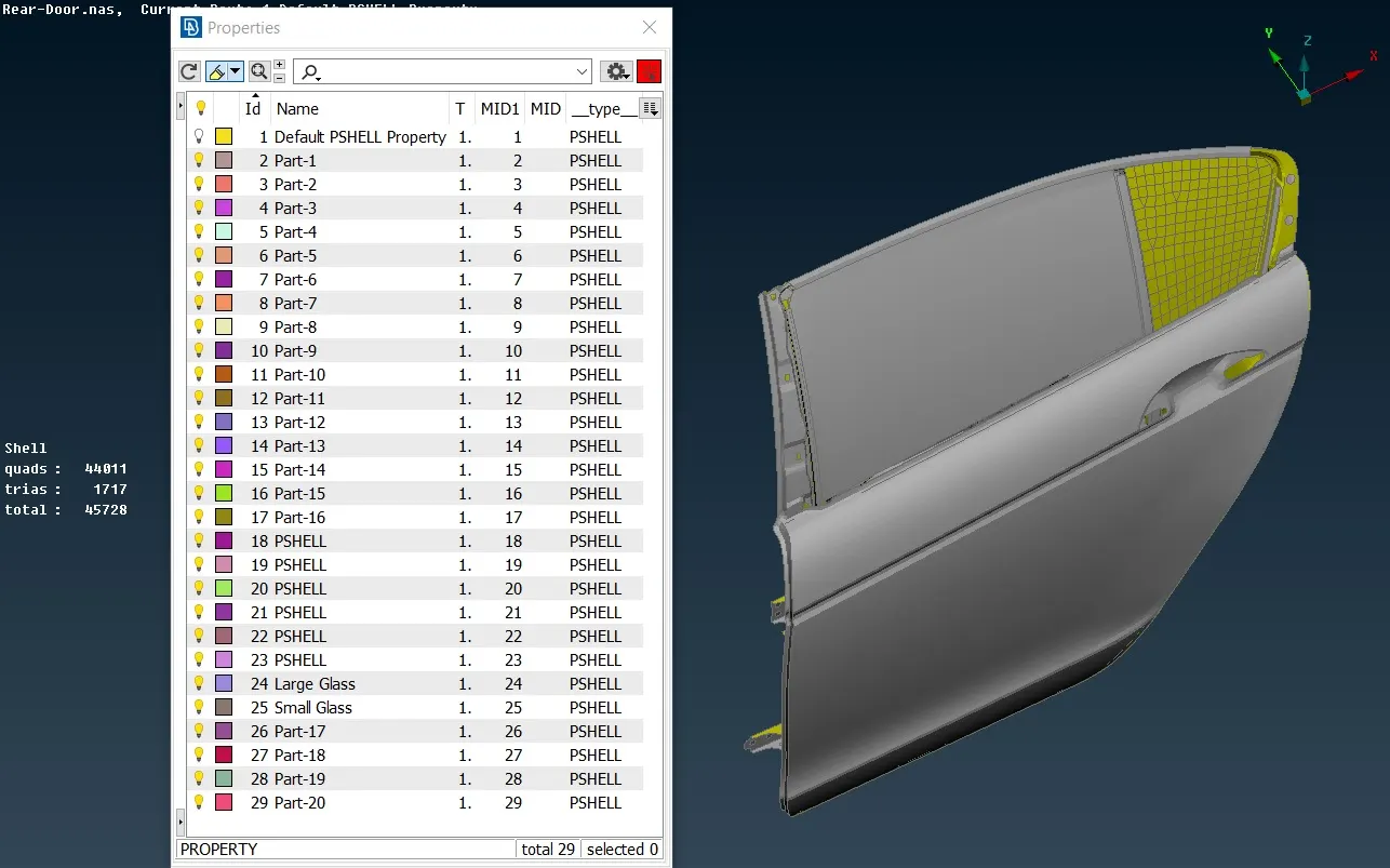
Figure 1.1 Seperate PID for Components
2. Connections
There are different type of connection representation available in ANSA for bolted joints, welded joints (spot and seam weld) and bush type connection between the car door glass window and weather strips as glass is brittle and bolted and welded joints cannot be used. These connections and their implementation in the FE model is discussed below.
2.1 Two Node RBE-2
This is used for FE representation of Bolted Joints in the back door body and Hinge as shown in Figure 2.2. Here the bolt is represented by a line in the middle of the spiders.
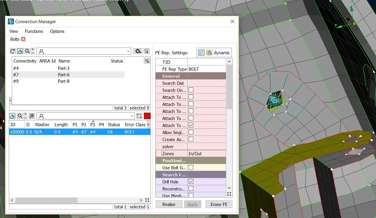
Figure 2.1 Two Node RBE-2 Representation for Bolted Connection
The two node RBE-2 is also used in door hinge mechanism and it is implemented by removing the sixth degree of freedom such that the DOF of rotation about Z axis is not restricted. The representation is shown in Figure 2.2 below.
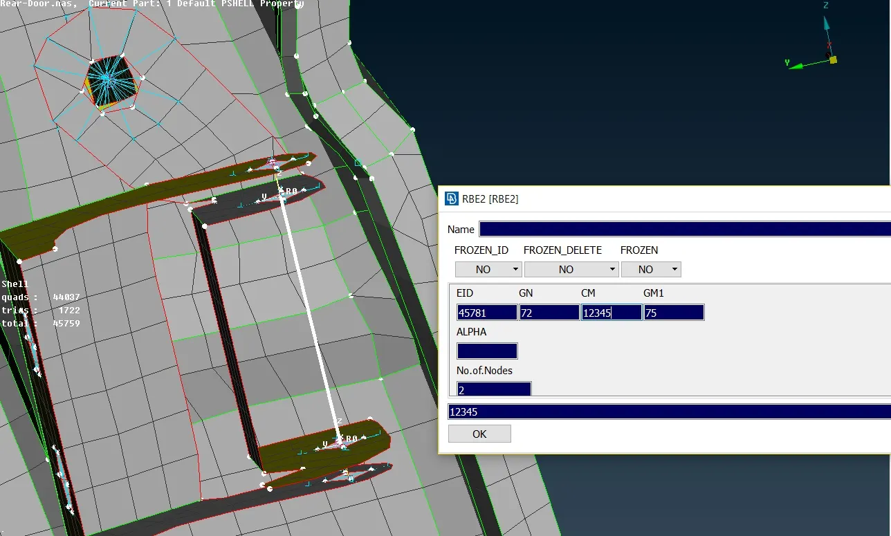
Figure 2.2 Two Node RBE-2 Representation (with relaxed rotational DOF about Z Axis)
A concentrated mass of 100 gm at the middle of two node RBE-2 element is used to model the door handle as shown in Figure 2.3. This type of connection is also known as conmass connection.
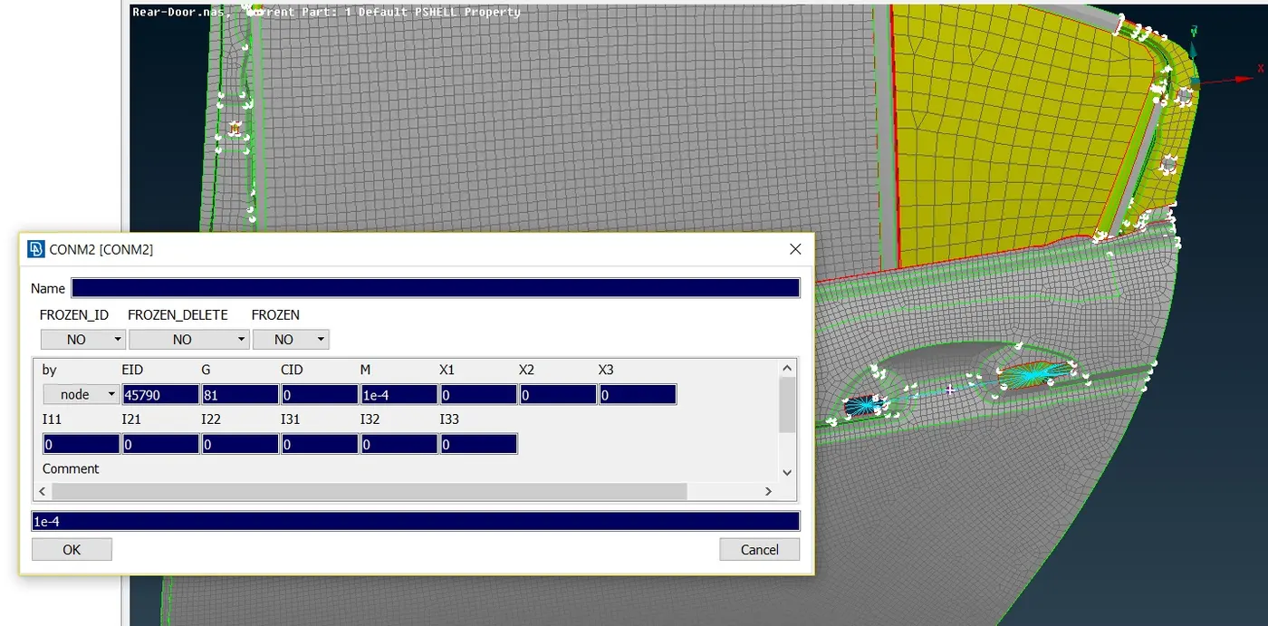
Figure 2.3 Implementation of Door Handle with two node RBE-2 element and a concentrated mass
2.2 Clustered RBE-2
In clustered RBE-2 the bolt representation is not shown by a line. It is used to make the parts rigid. This connection is shown in Figure 2.3. The check arm in the door which controls the amount of door rotation is also realized using this connection.
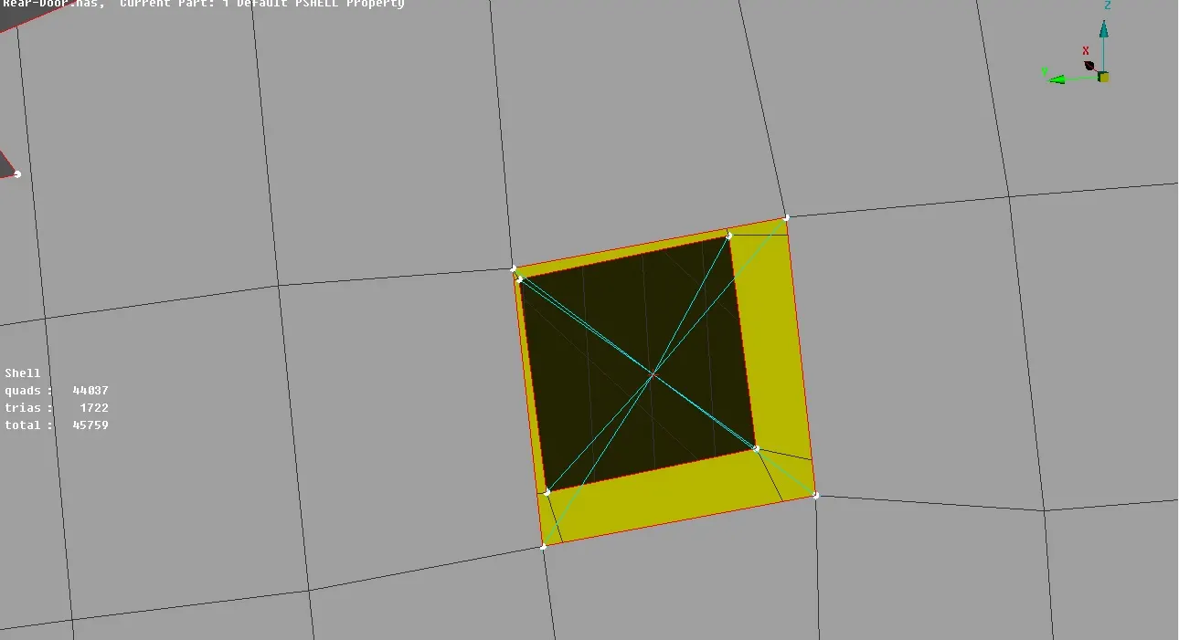
Figure 2.3 Clustered RBE-2 Representation
2.4 Spot Welds
The spot weld representation is done by RBE3-HEXA-RBE3 element which is a solid element. The primary difference with the RBE-2 element is that here the centre node is the slave node and the nodes on the perimeter is the master node. The representation is shown in Figure 2.4
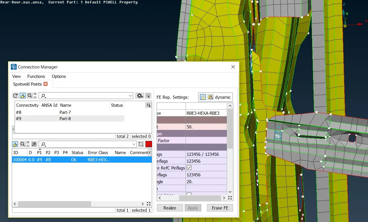
Figure 2.4 Spot Weld Representation using RBE3-HEXA-RBE3
2.5 Bush Connection
The glass is modeled in closed position and bush type connection between glass and weather strip is realized by using RBE3-CBUSH-RBE3 element.
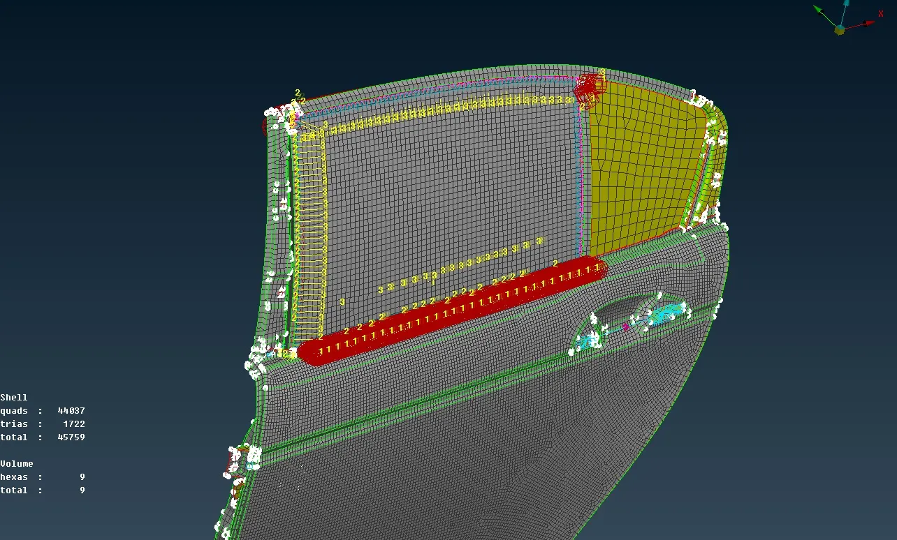
Figure 2.5 RBE3-CBUSH-RBE3 element representation
A proper value of stiffness has to be assigned for the bush elements before running the simulation. It is shown in Figure 2.6
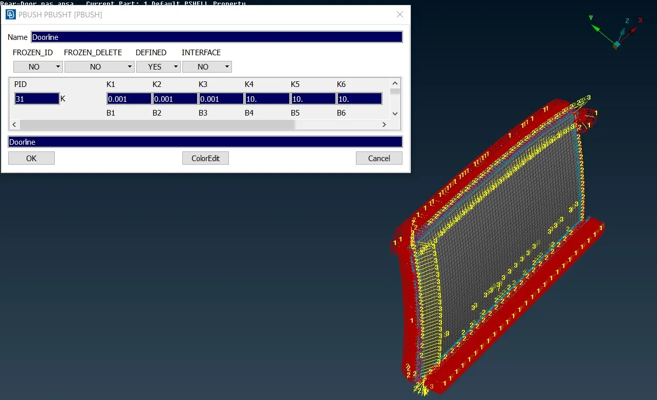
Figure 2.6 Stiffness Value Assignment for Bush Elements
The CBUSH elements are initially aligned to local co-ordinate system and thus for uniformity it has to be aligned to global co-ordinate system. It is depicted in Figure 2.7
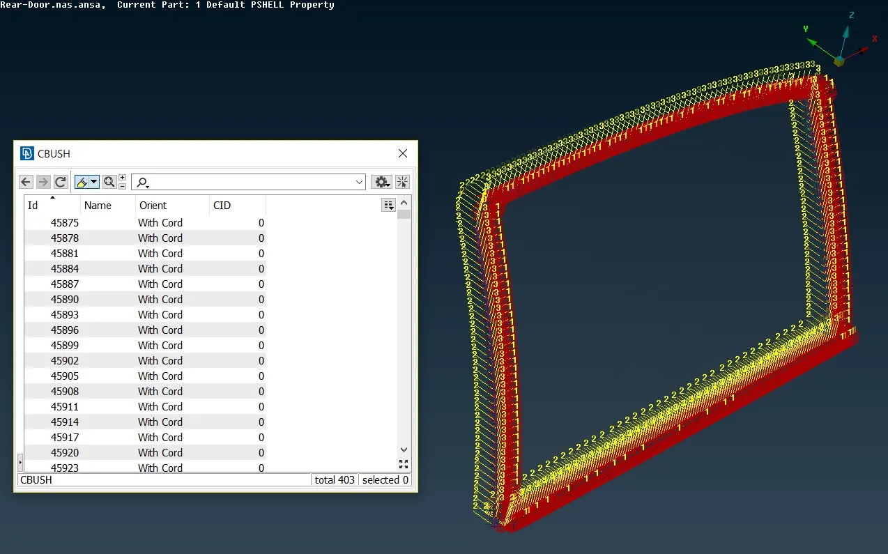
Figure 2.7 Local to Global Coordinate system for CBUSH elements
4. Learning Outcome
In this challenge, use of different connection and their representation in FE model has been realized. Some of the new things learned are RBE2, RBE3, Spot Weld and Con mass connection, orientation of elements along global co-ordinate axis.
5. Conclusion
The final model after all the necessary connections is shown in Figure 5.1. The back glass will be fixed and will not slide up and down like the front glass but as it is also connected with the weather strips CBUSH elements has been realized in this region as well.
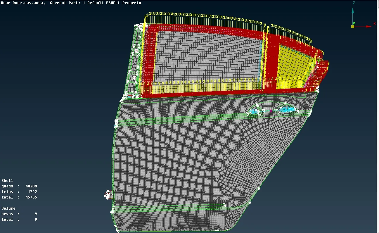
Figure 5.1 FE Model with all Connections