Week - 4
Objective-
- To implement control logic of a “washing machine” using Stateflow as per given sequence:
- If the power supply is available, the system gets activated
- If the Water supply is not available, stop the process & indicate through LED
- Soaking time should be 200s followed by Washing time of 100s.
- Then rinsing happens for next 20s & dryer runs for 50s
After all the processes have completed turn on the finished LED
2. To make a Simulink chart for the “Gear shift” logic as per below conditions:
Speed Range(kmph) Gear
0 to 15 1
16 to 25 2
26 to 40 3
41 to 60 4
Above 61 5
and to give speed input while the simulation is running & display the gear number.
Report
1) To implement control logic of a “washing machine” using Stateflow
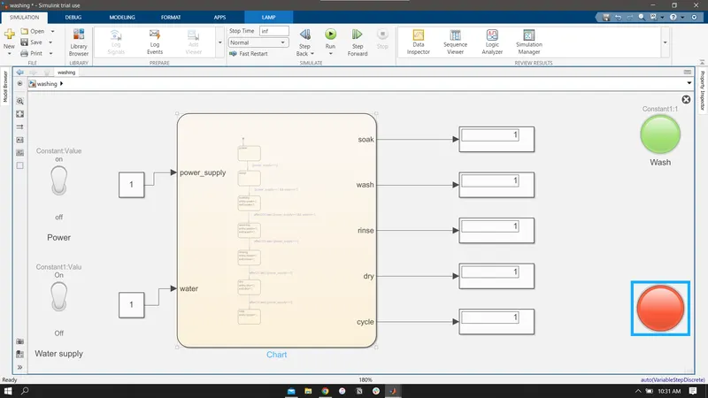
Simulink Model
Chart
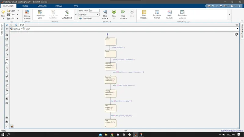
Chart Parameters
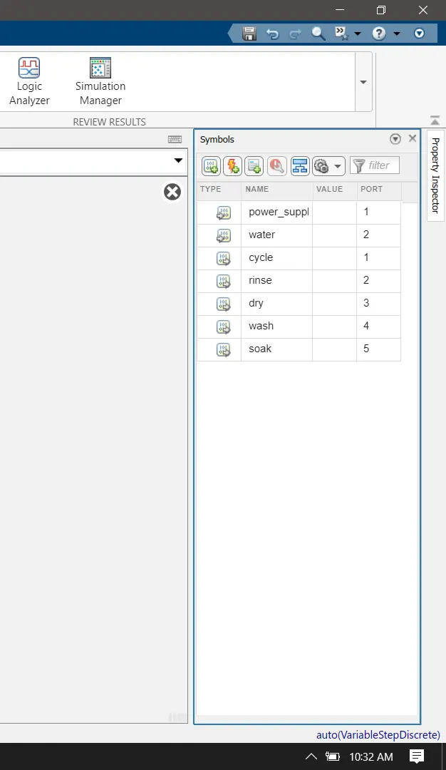
- water, soak, wash, rinse, dry, cycle as output data
- water and power_supply as input data o
- The power supply and water supply is given using toggle switch which provide value '1' when "ON" and value '0' when "OFF" condition.
- When power supply is "OFF" then the logic does not activates, it activates only when the power supply is in "ON" condition.
- When Water supply is given then the logic process to the next state otherwise the Lamp will show "RED" colour and the process halts
- When the water supply is given, the Lamp will show "GREEN" colour and the logic will process to the next state.
- The next state is Soaking, here the logic stays for 200 seconds as the delay time to go to th next state is given as 200 seconds.
- After 200 seconds, washing state process for 100 seconds as delay time is 100 seconds.
- After washing state, rinsing state process for 20 seconds.
- After rinsing state, dry state process for 50 seconds.
- When the above process is completed the Lamp will show "RED" colour.
Output
Condition-1: when Water Supply is OFF.
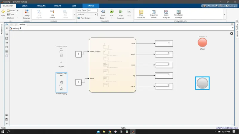
Indicator (lamp) of water supply is showing Red i.e., When there is no water supply the process is terminated and Lamp indicator is used to indicate that state.
condition 2 - when water supply is on
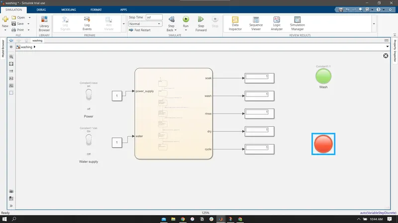
As all states have been executed , the lamp indicator shows 'RED' indicating the finish or executiion of the complete cycle.
2) To make a Simulink chart for the “Gear shift” logic as per below conditions:
Speed Range(kmph) Gear
0 to 15 1
16 to 25 2
26 to 40 3
41 to 60 4
Above 61 5
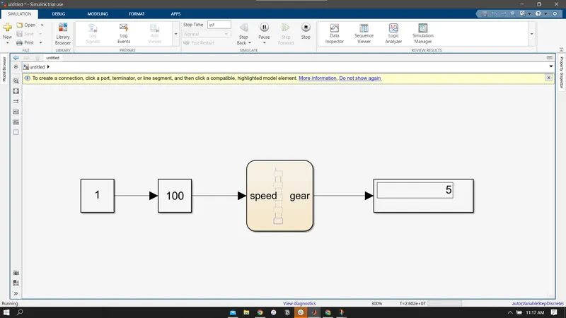
Simulink Model
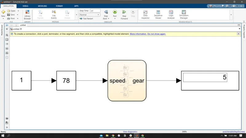
Stateflow Chart
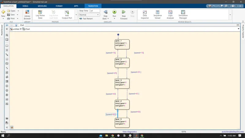
Chart parameters
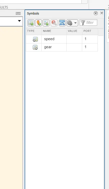
Input Data- speed
Output Data - gear
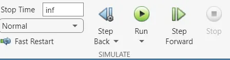
Here we gave time as 'Inf' for our simulation
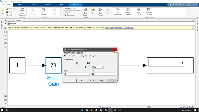
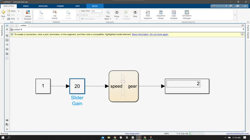
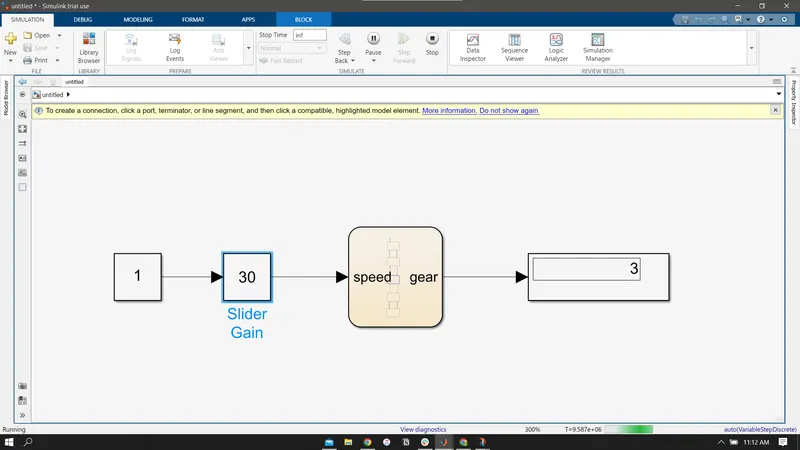
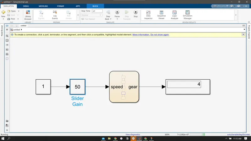
We use slider gain to provide input to the chart.
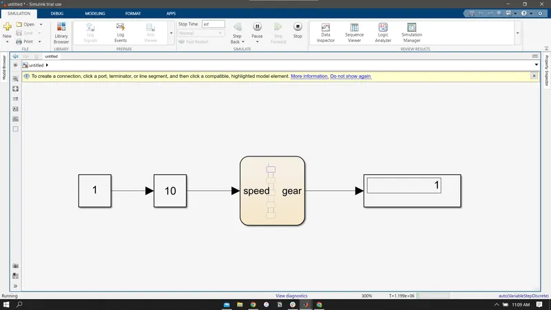
Output
Speed range: 0 to 15kmph.
Input speed: 10kmph.
Gear 1
Speed range: 16 to 25 kmph.
Input speed: 20 kmph.
gear 2
Speed range: 26 to 40 kmph.
Input speed: 30 kmph.
gear 3
Speed range: 41 to 60 kmph.
Input speed: 50 kmph
gear 4
Speed range: above 60kmph.
Input speed: 100 kmph.
gear 5