Week - 4
AIM: To Implement Control logic of a “Washing Machine” using stateflow as per given sequence.
Objectives:
- Understand and implement the logic control of a State machine using stateflow
- If the power supply is available, the system gets activated
- If the water supply is not available, stop the process and indicate through LED
- Soaking time should be 200 seconds followed by washing time of 100 seconds
- Then rinsing happens for next 20 seconds and dryer runs for 50 seconds.
- After all the processes have completed, turn on the finished LED.
Blocks Used:
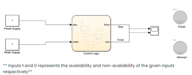
Constant: To provide a constant signal to the Simulink environment
Flowchart: Implement logic control of the washing machine
Scope: To view the change of the parameters with respect to time
Lamps: Glows according to the allotted signal
Simulink model:
Sub-systems:
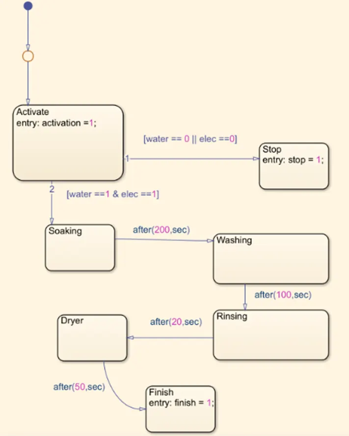
- This shows the logic of the state washing machine
- If the water and power supply is available then the machine will proceed its further operation
- If either of them is absent the machine will stop with an interruption error.
- The rest of the processes are explained in the above stateflow chart.
Outputs:
- When both the power supply and water supply is provided: -
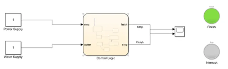
The green light will glow indicating the processes are successfully completed!
- When either of the power and water is not provided: -
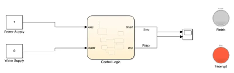
The red light will glow indicating the interruption in the process.
Conclusion:
- The logic control of the state machine could be executed as per required.
- The real time changes in the simulation could also be observed if the simulation time is set to infinity.
- More features could be added like different modes of washing.
Aim: To make a Simulink chart for the gear shift logic as per given conditions.
Objectives: Following condition are to be satisfied: -
|
Speed Range(kmph) |
Gear |
|
0 to 15 |
1 |
|
16 to 25 |
2 |
|
26 to 40 |
3 |
|
41 to 60 |
4 |
|
Above 61 |
5 |
** Given speed input while the simulation is running and display the gear number**
Blocks used:
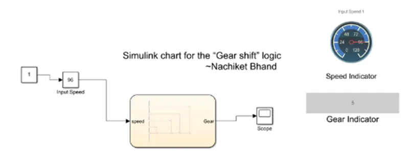
Slider Gain: To change the input speed value in real time simulation
Display Dashboard: To display the gear associated with a given speed
Scope: To view the shift in gear with respect to time
Chart: To set the control logic for gear shift mechanism
Gauge: To display the real time input speed
Simulink Model:
Subsystem:
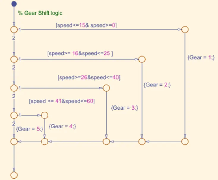
The image shows the logic for gear change phenomenon.
Output:
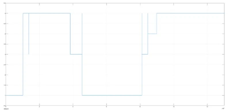
This shows the change in the gears for a time independent varying speed.
Conclusion: -
- Many automobile systems could be designed according to the user with the help of state machine.
- The above simulation represents the real time representation of a vehicle’s gear shift paradigm.