Week -2
AIM1: To make a Simulink model of Door belll using solenoid block and to make a simulink model of a thermistor to sense the temperature of heater and turn off the fan as per the temperature conditions.
DOORBELL USING SOLENOID:
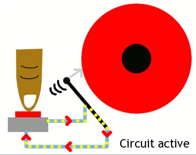
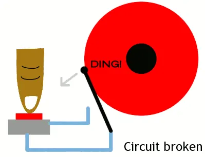
The solenoid is an electromagnet. On passing current through the conducting wires a magnetic field is generated around it which attracts magnetic materials. This phenomenon is used to attract the plunger to ring the bell. When the switch of the bell is pressed the current passess through the circuit, exciting hte electromagnet which attracts the plunger. The plunger attraction will help to create a ringing sound. The setup is done in such a way that once the plunger hits the bell, the circuit breaks and due to no electricity through the solenoid, the plunger gets back to its original position by the help of a spring. This phenomenon continues and ringing sound occurs whenever the bell is pressed.
SIMULINK MODEL:
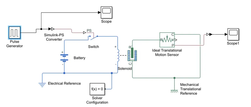
Blocks used to create the model:
1. Pulse Generator
2. Switch
3. Battery
4. Solenoid
5. Ideal Translational motion sensor
6. Mechanical Translational reference
7. Electrical reference
8. Scope
EXPLANATION OF MODEL:
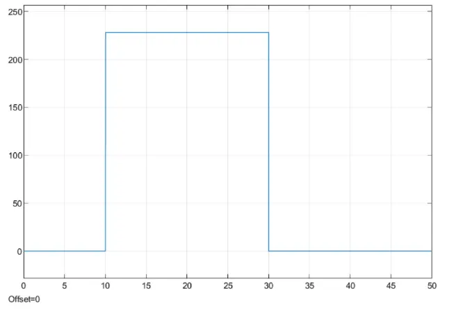
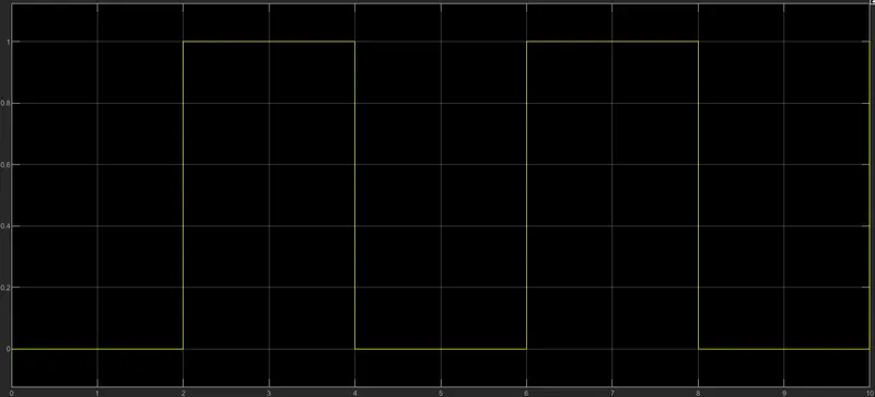
As per the given conditions switch is closed every 2 seconds and then released. The pulse generator is used to create square wave pulses at regular intervals. The block waveform parameters, amplitude, pulse width, period and phase delay determines the shape of the waveform.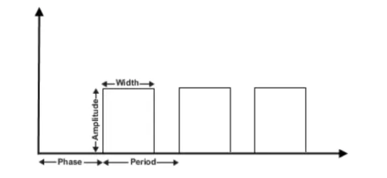
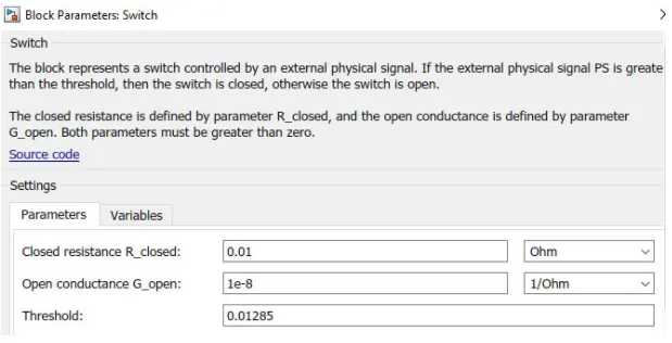
- Switch block is controlled by external physical signal and if the external physical signal is greater than the switch is closed or else it will be open.
- The blocks are connected with each other. The negative terminals are connected to their respective electrical and mechanical refrences. By connecting the blocks we complete the circuit.
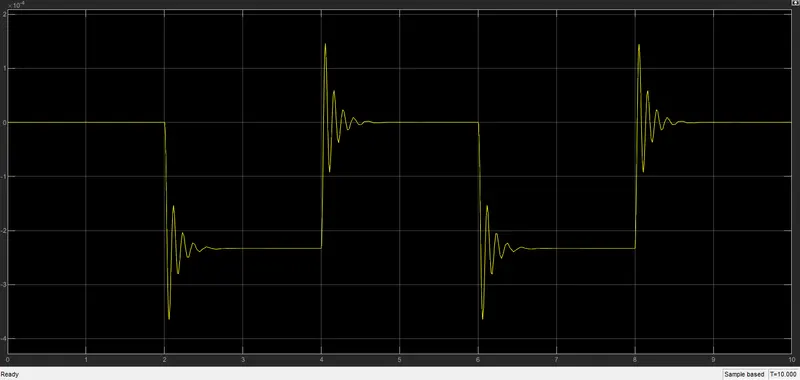
- Scope is connected with the ideal translational sensor to get the output.
The signal from the pulse generator is converted using simulink ps convertor and is given to the input switch. A solenoid is introduced and battery is connected to it. The voltage of the battery connected was made as same as that of the rated voltage of the solenoid. The switch is also connecte to the same circuit.
The position of the solenoid plunger is measured using an ideal transalational motion sensor connected to the circuit.
AIM2: To use a thermistor to sense the temperature of a heater & turn on or turn off the fan as per the given conditions.
THERMISTOR: Thermistor is a type of resistor whose resistance is strongly dependent on temperature, more so than in standard resistors. The word is a combination of thermal and resistor. Thermistors are widely used as inrush current limiters, temperature sensors (negative temperature coefficient or NTC type typically), self-resetting overcurrent protectors, and self-regulating heating elements (positive temperature coefficient or PTC type typically). An operational temperature range of a thermistor is dependent on the probe type and is typically in between −100 ⁰C and 300 ⁰C.
Procedure:
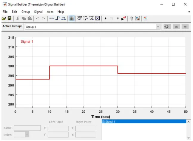
1. The requirement is such that the fan should be turned on when the temperature sensed is greater than 25 degree celcius. Accordin to the inputs provided we have given the signal by using signal builder. For 0-10 secs 20 degree clecius, 10-30 secs 27 degree celcius and 30-50 secs 23 degree celcius. In the signal builder we have give the temperature as kelvin as the thermistor takes values only in kelvin.
2. After that we build a thermistor circuit using thermistor block, a current sensor, an ammeter and a power source or battery to complete the circuit. The output of the circuit will be connected to the input switch of the fan circuit.
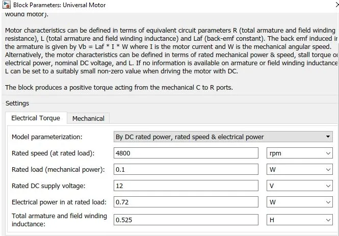
3. Now we provide the motor parameters for getting optimum power output of the fan. Then we connect a ratational motion sensor to find the angular velocity of the motor. Then we connect a reference for each of these.
4. We finally obtain a graph for the fan speed and it is contraint to the value. i.e 25 celcius as mentioned in the question. The simulink model is shown below.