Week - 4
Aim :-
- To implement control logic of a washing machine using Stateflow as per given sequence.
- To build a Simulink Chart for the ‘Gear Shift’ logic as per below conditions.
Workflow :-
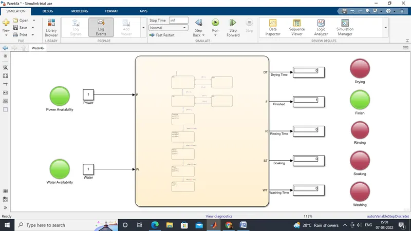
- Simulink model for Washing Machine (when water supply is available):-
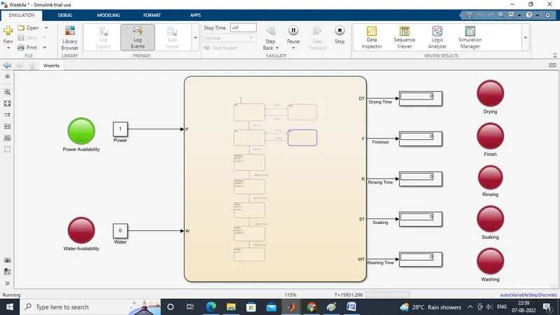
- Simulink model for Washing Machine (when water supply isn't available):-
- Control logic chart :-
Workflow :-
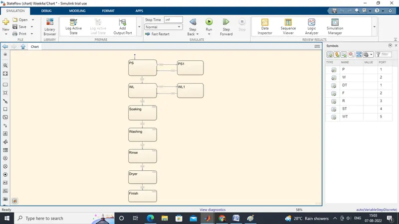
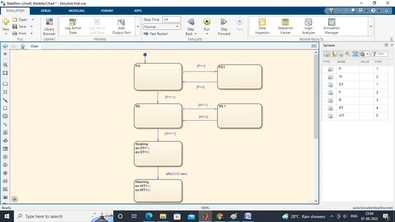
- In the above model,at first the Chart mode is accessed and then after moving inside the chart the state machine is implemented as per given conditions.
- Power and water inputs are given and the corresponding states are being defined as shown in the Stateflow logic.
- PS and PS1 represents Power state and Power State 1.And PS1 is defined in addition to PS to transit to it when power suppy is unavailable and similarly done for Water supply as well.
- WL and WL1 represents Water Level states at which the water is supplied.
- In Soaking state,the output ST i.e.,Soaking Time variable is being defined for showing the state condition at different time instance.
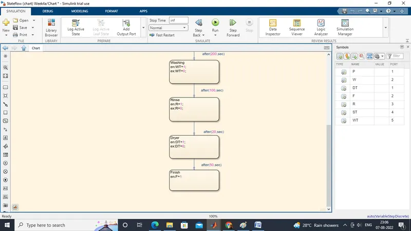
- Soaking of clothes should be done for 200 seconds as per the given conditions.
- Similarly,done for Washing,Rinsing & Drying state.
- From Soaking state to Drying state,these are delay driven.
- Lastly,for implementing the Drying state,Finish state is introduced and then the simulation stops.
- Lamps are attached to each state for knowing their status and also display blocks are attached for showing the on/off values while the simulation is running.
Simulink model for Gear Shifting in Automobiles:-
Stateflow Chart :-
Workflow :-
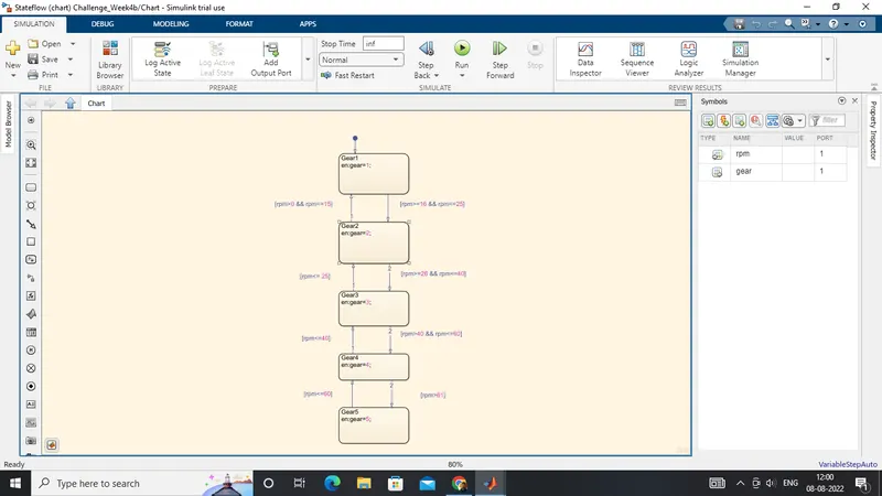
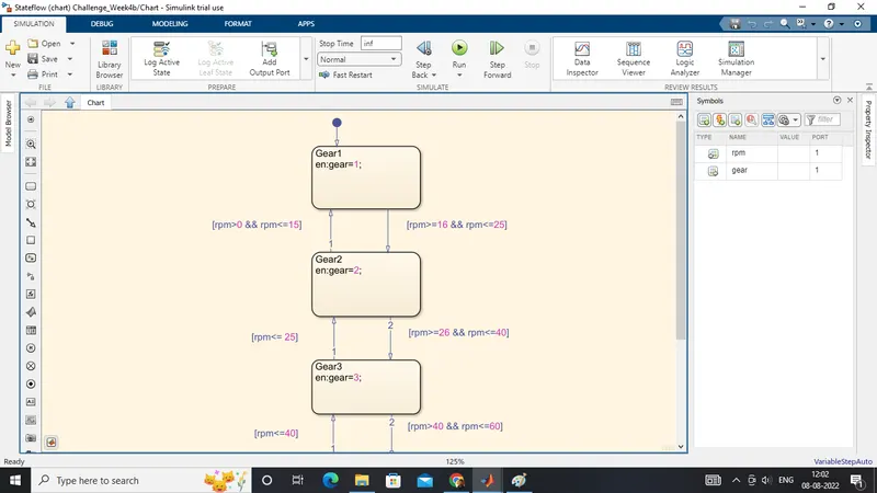
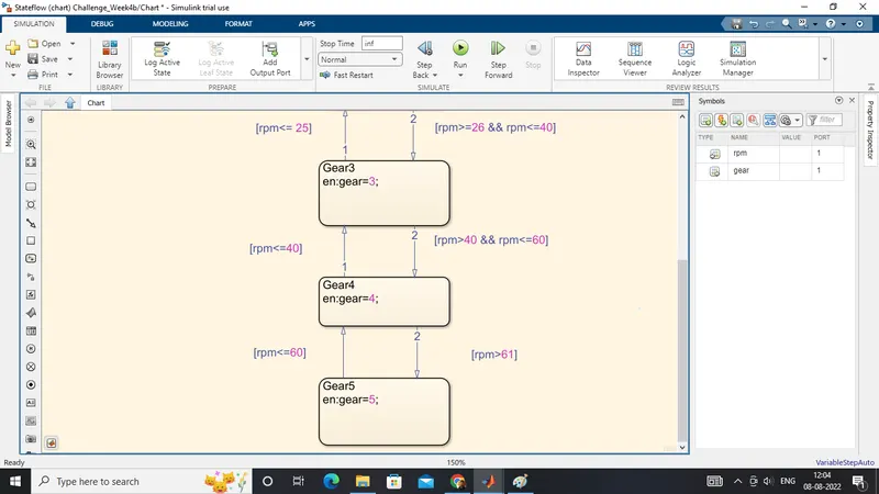
- After accessing the chart mode,input and output variables are defined using the Symbols Pane.
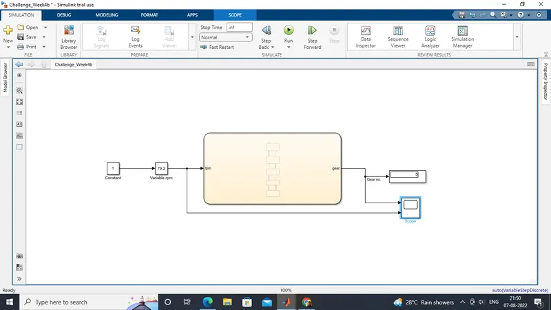
- Slider gain block is used to input the rpm values to change it in real time simulation.
- Five different states along with the respective input transitioning conditions are defined for representing the Gear Number.
- These states are getting transitioned as per the real time inputs provided by rpm block.
Scope:-
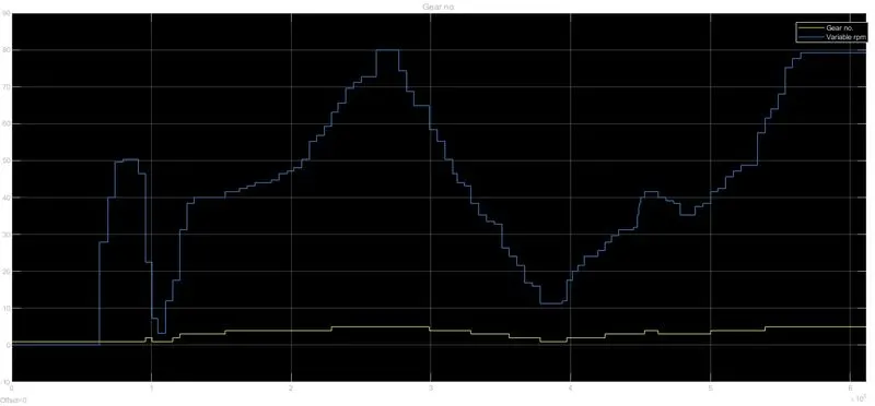
The given plot shows that the Gear shift occurs according to the real time rpm provoided during the simulation.