Week - 4
AIM : To implement control logic of a “washing machine” using Stateflow as per given sequence:
- If the power supply is available, the system gets activated
- If the Water supply is not available, stop the process & indicate through LED
- Soaking time should be 200s followed by Washing time of 100s.
- Then rinsing happens for next 20s & dryer runs for 50s.
MODEL :
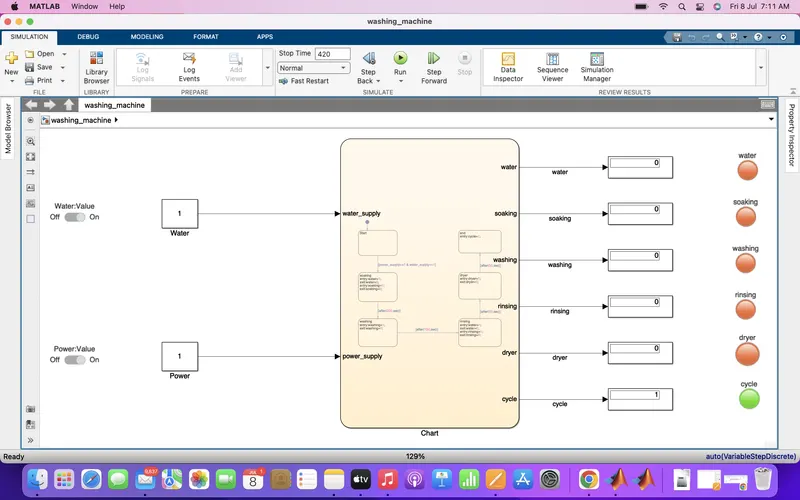
CHART DIAGRAM :
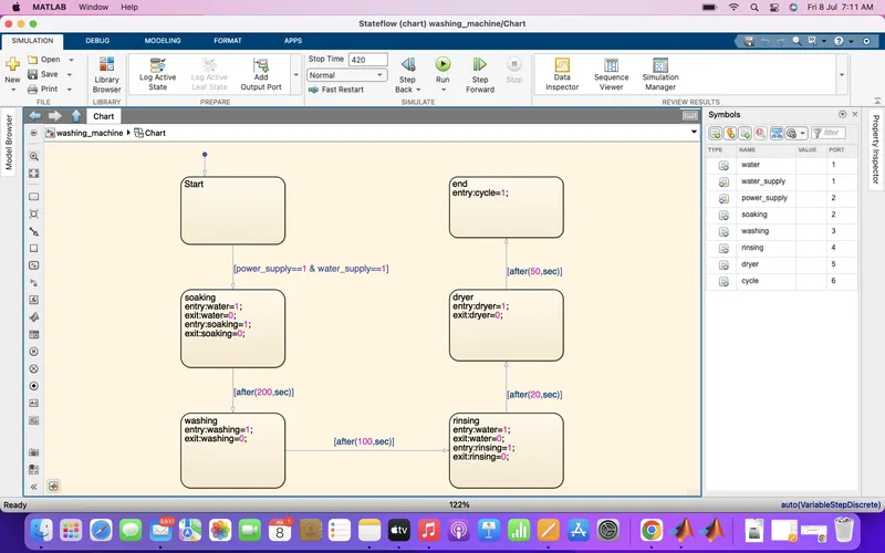
INPUT - Water supply, Power supply.
OUTPUT - Water, Soaking, Washing, Rinsing, Dryer, Cycle.
EXPLANATION :
1. At first, Chart block was selected, in which, all the logic control was done including start, soaking, washing, rinsing, dryer and end along with their respective timing.
2. Then, two constant block were selected for water and power along with their switch, in which, 1 means on and 0 means off.
3. In the output, all the respective outputs were connected with their display blocks along with lamp.
CONCLUSION :
The automatic washing machine model runs successfully.
STUDY 2
AIM : To make a Simulink chart for the “Gear shift” logic as per below conditions:
Speed Range(kmph) Gear
0 to 15 1
16 to 25 2
26 to 40 3
41 to 60 4
Above 61 5
Give speed input while the simulation is running & display the gear number.
MODEL :
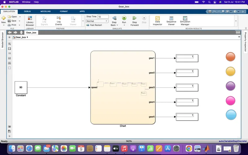
CHART DIAGRAM :
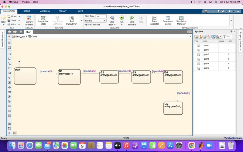
INPUT - Speed.
OUTPUT - Gear1, gear2, gear3, gear4, gear5.
EXPLANATION :
1. At first, Chart block was selected in which, all logic control was done including start, G1,G2,G3,G4,G5.
2. Then, all the speed range inputs were provided for the respective gears as mentioned in the aim.
3. A constant block was selected for the speed input of 90.
4. In output, display blocks were attached to their respective gears along with lamp.
5. In the lamp, different colours were provided for different gears such as when gear1 is on- orange, gear2 on- yellow, gear3 on- purple, gear4 on- pink, gear5 on- blue where in display 1 is on and 0 is off.
CONCLUSION :
The Gear box model runs successfully.