Week -2
AIM : 1. To make a Simulink model of Doorbell using solenoid block.
2. To use a thermister to sense the temperature of a heater and turn on or off the fan.
STUDY 1 : DOOR BELL
THEORY : A door bell here is basically an electric bell which is a mechanical or electronic bell that functions by means of an electromagnet. When an electric current is. applied, it produces a repetitive buzzing, clanging or ringing sound. Electromechanical bells have been widely used at railroad crossings, in telephones, fire and burglar alarms, as school bells, door bells, and alarms in industrial plants, since the late 1800s, but they are now being widely replaced with electronic sounders.
An electric bell consists one or more electromagnets, made of a coil of insulated wire around an iron bar I.e solenoid.
Solenoid : The solenoid is a coil of wire, and the plunger is made of soft iron. The magnetic field is formed around the coil when an electric current passes through it and draws the plunger in. We can say that the solenoid is responsible for converting electrical energy into mechanical work.
SIMULINK BLOCK FOR DOOR BELL :
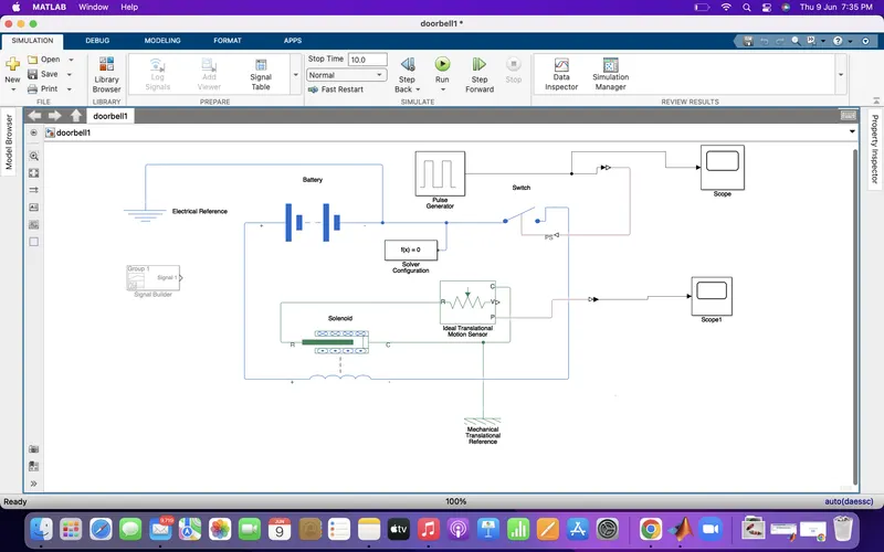
EXPLANATION :
In this simulink model, we used the following blocks to get our desired output.
- Pulse Generator : The pulse generator block generates square wave pulses at regular intervals. The block waveform, Amplitude, Pulse width, Period and Phase delay are all the parameters that determines the output waveform.
- Simulink-PS/PS-Simulink Convertor : It converts the simulink signal into a physical signal and vice-versa.
- Switch
- Battery
- Electrical Reference : It shows the connection to electrical ground.
- Solenoid : It converts electrical to mechanical work.
- Ideal Translational Motion Sensor : It is a motion sensor in mechanical translational systems.
- Mechanical Translational Reference : It is a reference connection in mechanical translation.
- Scope : It displays signals generated during simulation.
Parameters which are used are as follows :
Spring Constant (K) = 200 N/m
Damping = 2 N*s/m
Plunger mass = 0.05 kg
OUTPUT :
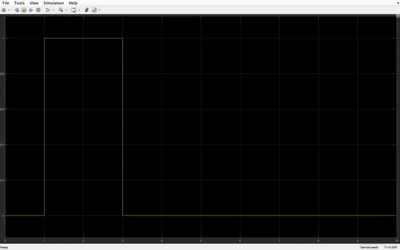
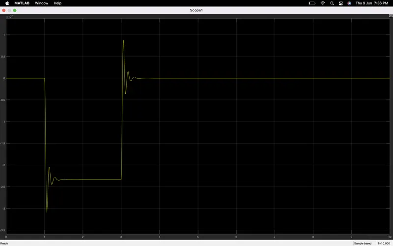
CONCLUSION :
In the above two waveform, there is phase delay of 1 sec and period of 2 sec i.e. we can observe that, the plunger moved from its original position to some amplitude with a phase delay. And then it hits the bell and pause there before coming to its initial position.
STUDY 2 : THERMISTER -
Temperature source: 20 °C from 0 to 10 seconds, 27 °C from 10 to 30 seconds, 23 °C from 30 to 50 seconds
Fan conditions: ON if the temperature above 25 °C, OFF otherwise.
THEORY : The term Thermistor comes from “thermal” and “resistor”. A thermistor is a type of resistor whose resistance is reliant on temperature; it’s a resistance thermometer. They are made from metallic oxide which is moulded into bead, disk or cylindrical shape and then enclosed with epoxy or glass.
Thermistors don’t work well with extreme temperatures but they are perfectly suited for measuring the temperature a certain point. They are precise when they’re used within a limited temperature I.e within 50 deg Celsius of the target temperature; this range is dependent on the base resistance.
SIMULINK BLOCK FOR THERMISTER TO SENSE THE TEMPERATURE OF A HEATER
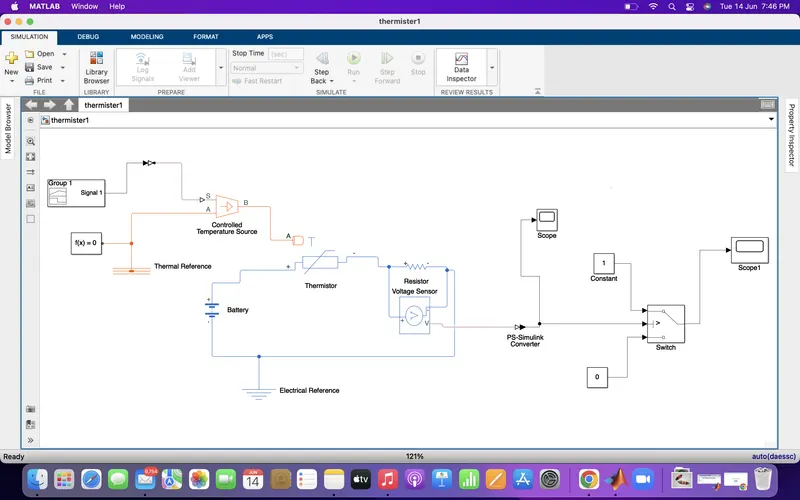
EXPLANATION : In this simulink, we used these following blocks which are as follows :-
1. Signal Builder - The Signal Builder block allows us to create interchangeable groups of piecewise linear signal sources and use them in a model. We can quickly switch the signal groups into and out of a model to facilitate testing. In the Signal Builder window, create signals and define the output waveforms. To open the window, double-click the block.
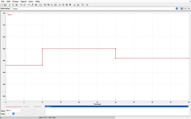
At 0 to 10 sec - 293K
At 10 to 30 sec - 300K
At 30 to 50 sec - 296K
2. Controlled Temperature Source - The Controlled Temperature Source block represents an ideal source of thermal energy that is powerful enough to maintain specified temperature difference across the source regardless of the heat flow consumed by the system.
Connections A and B are thermal conserving ports corresponding to the source inlet and outlet, respectively. Port S is a physical signal port, through which the control signal that drives the source is applied. You can use the entire variety of Simulink® signal sources to generate the desired heat flow variation profile. The temperature differential across the source is directly proportional to the signal at the control port S.
3. Thermistor - A thermistor is a type of resistor whose resistance is strongly dependent on temperature, more so than in standard resistors. The word thermistor is a portmanteau of thermal and resistor.
4. Resistor - The Resistor block models a linear resistor, described with the following equation:
V=I·R
where:
-
V is voltage.
-
I is current.
-
R is resistance.
5. Voltage Sensor - The Voltage Sensor block represents an ideal voltage sensor, that is, a device that converts voltage measured between two points of an electrical circuit into a physical signal proportional to the voltage.
6. Switch
7. Constant Block
8. Scope
9. Simulink-PS/PS-Simulink Convertor
OUTPUT :
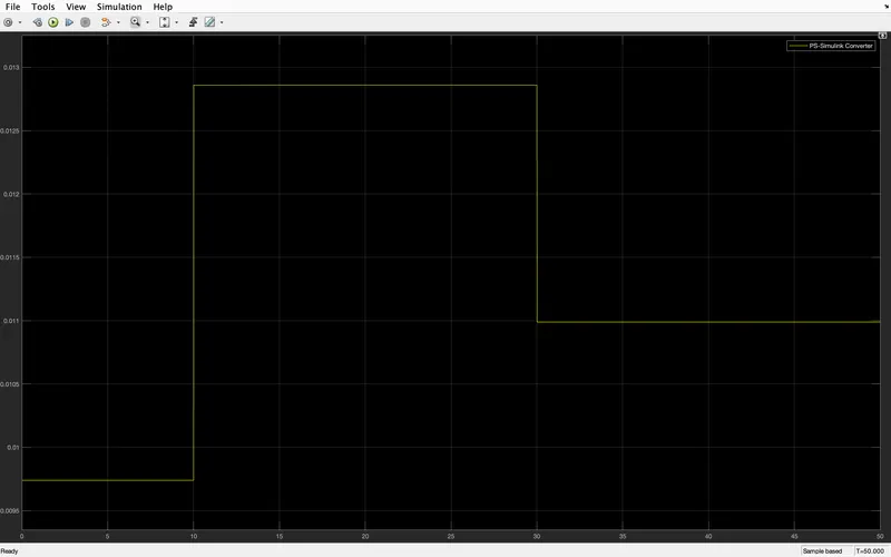
CONCLUSION : Both the simulation works successfully.