Week - 4
Aim : To Implement control logic of a “washing machine” using Stateflow as per given sequence:
- If the power supply is available, the system gets activated
- If the Water supply is not available, stop the process & indicate through LED
- Soaking time should be 200s followed by Washing time of 100s.
- Then rinsing happens for next 20s & dryer runs for 50s
Principle:
A washing machine (Laundry machine, clothes washer, washer, or simply wash) is a home appliance used to wash laundry. The term is mostly applied to machines that use water as opposed to dry cleaning (which uses alternative cleaning fluids and is performed by specialist businesses) or ultrasonic cleaners. The user adds laundry detergent, which is sold in liquid or powder form, to the wash water.
The following are descriptions of the cycles you might use on your washing machine:
- Wash -- Fill the machine to a certain water level, dispense any chemicals from dispensers, agitate the load for a certain amount of time and drain the water
- Rinse -- Fill the machine to a certain water level, agitate the load for a certain amount of time and drain the water
- Spin -- Spin the basket rapidly for a certain amount of time with the drain open so most remaining water is removed by the centrifugal force
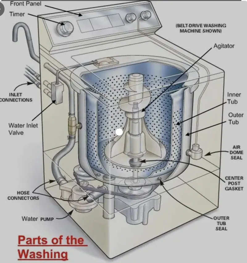
Working of the washing machine
Model
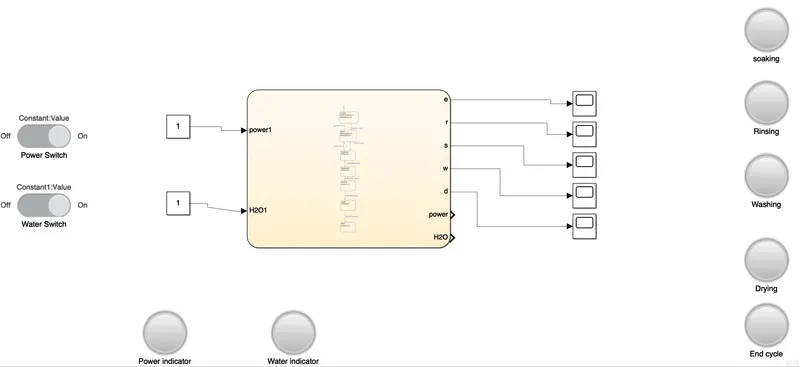
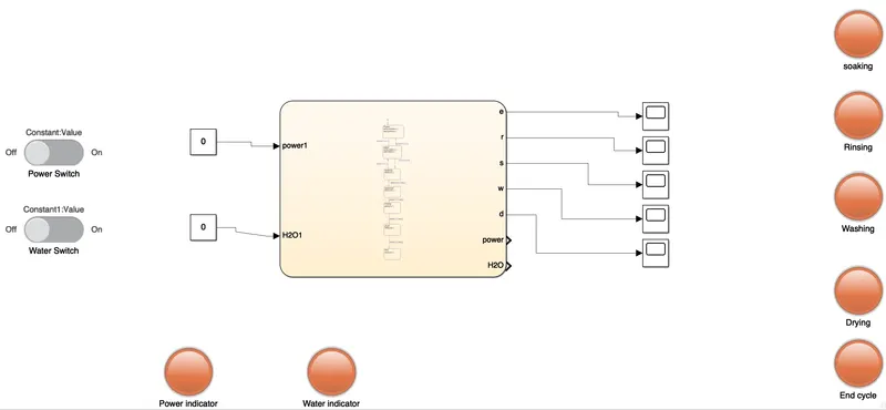
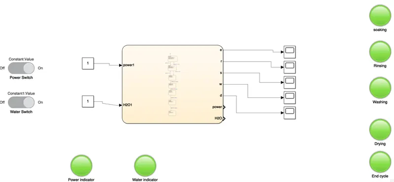
The above shown image is the model of the washing machine where Slider Switch is used to turn on or off both water switch and power. Lamp Block is used to indicate the state of the model whether the cycle are running or not.
Chart Block
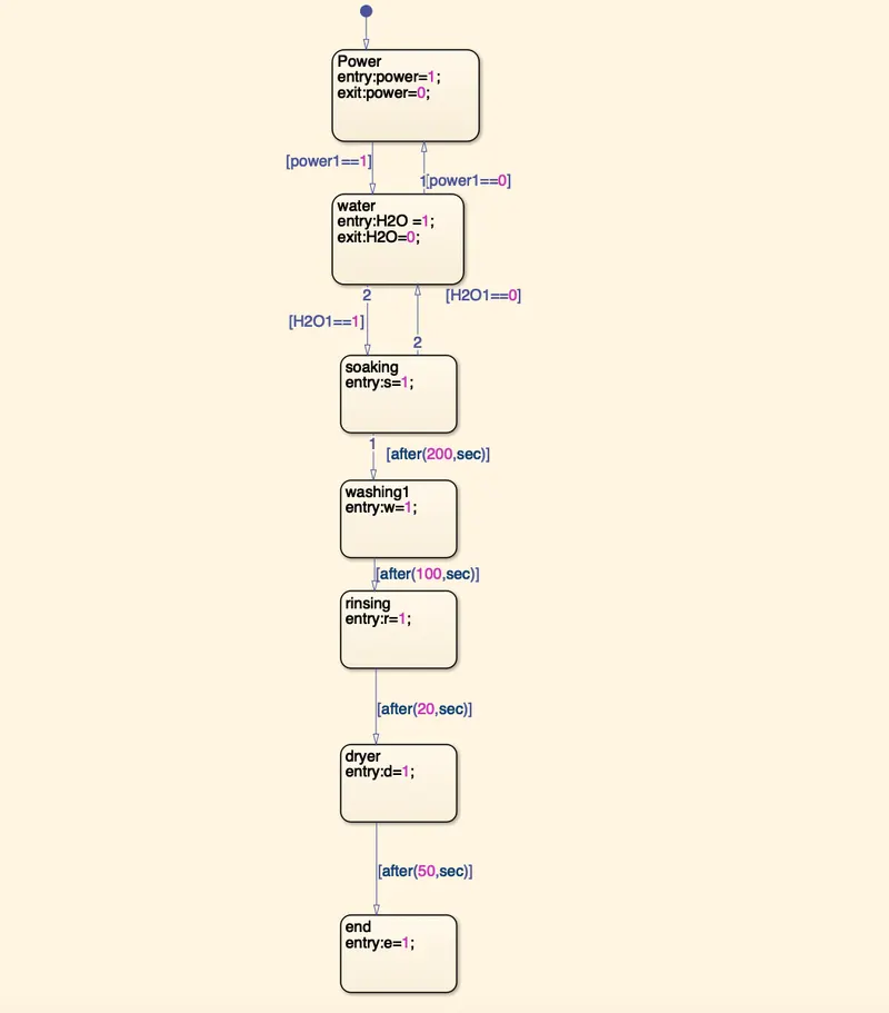
The above image is the state flow
- 1 and 0 indicates whether the power and water unit is on or off
- If both power unit and water unit is 1 then soaking cycle is started for period of 200 sec
- Subsequently all the cycle like washing,rinsing,dryer is carried out
- If either of the power unit or the water unit is switched off the cycle is ended
When the water is Switched off
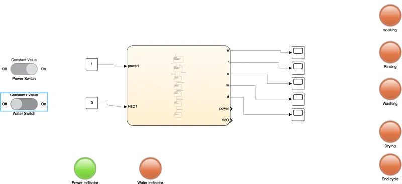
When Both power and water unit is switched off
When both Power and Water unit is switched on
Objective 2
Aim:To Make a Simulink chart for the “Gear shift” logic as per below conditions:
Speed Range(kmph) Gear
0 to 15 1
16 to 25 2
26 to 40 3
41 to 60 4
Above 61 5
Principle:A manual transmission (MT), also known as manual gearbox, standard transmission (in Canada, the United Kingdom, and the United States), or stick shift (in the United States), is a multi-speed motor vehicle transmission system, where gear changes require the driver to manually select the gears by operating a gear stick and clutch (which is usually a foot pedal for cars or a hand lever for motorcycles)
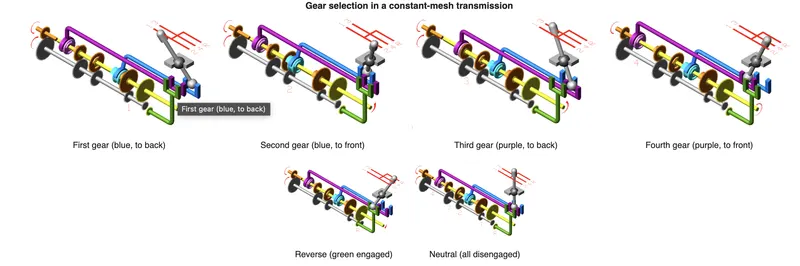
A manual transmission requires the driver to operate the gear stick and clutch in order to change gears (unlike an automatic transmission or semi-automatic transmission, where one (typically the clutch) or both of these functions are automated). Most manual transmissions for cars allow the driver to select any gear ratio at any time, for example shifting from 2nd to 4th gear, or 5th to 3rd gear. However, sequential manual transmissions, which are commonly used in motorcycles and racing cars, only allow the driver to select the next-higher or next-lower gear.
In a vehicle with a manual transmission, the flywheel is attached to the engine's crankshaft, therefore rotating at engine speed. A clutch sits between the flywheel and the transmission input shaft, controlling whether the transmission is connected to the engine (clutch engaged- the clutch pedal is not being pressed) or not connected to the engine (clutch disengaged- the clutch pedal is being pressed down). When the engine is running and the clutch is engaged (i.e., clutch pedal up), the flywheel spins the clutch plate and hence the transmission.
The design of most manual transmissions for cars is that gear ratios are selected by locking selected gear pairs to the output shaft inside the transmission. This is a fundamental difference compared with a typical hydraulic automatic transmission, which uses an epicyclic (planetary) design, and a hydraulic torque converter. An automatic transmission that allows the driver to control the gear selection (such as shift paddles or "+/-" positions on the gear selector) is called a manumatic transmission, and is not considered a manual transmission. Some automatic transmissions are based on the mechanical build and internal design of a manual transmission but have added components (such as computer-controlled actuators and sensors) which automatically control the timing and speed of the gear shifts and clutch; this design is typically called an automated manual transmission (or sometimes a clutchless manual transmission)
Model
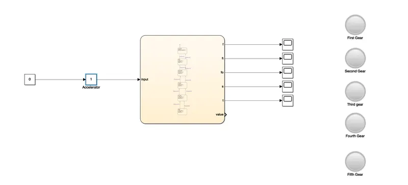
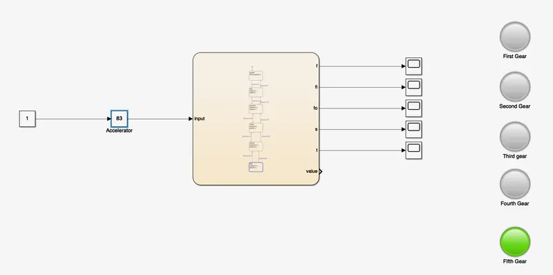
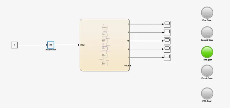
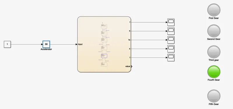
The above shown image is the model of manual gear box system
- Slider switch is used vary the speed of vehicle
- Lamp Block is used to indicate which gear is selected according to the speed
- Chart Block contains control logic of the gear system
Chart Block
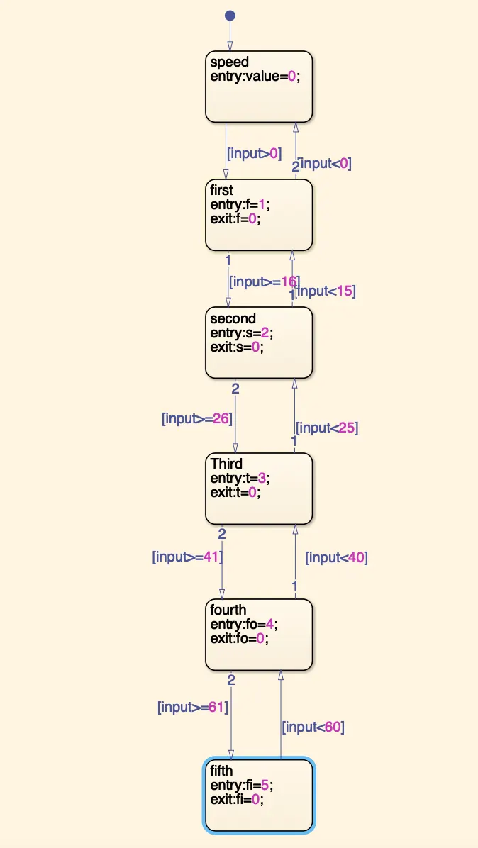
Explanation
- When the Slider switch is Zero the gear indicator will not be selected
- As we vary the Speed the gear indicator will be selected according to the speed
- The gear will be indicated according to the speed
-
Speed Range(kmph) Gear
0 to 15 1
16 to 25 2
26 to 40 3
41 to 60 4
Above 61 5
First gear
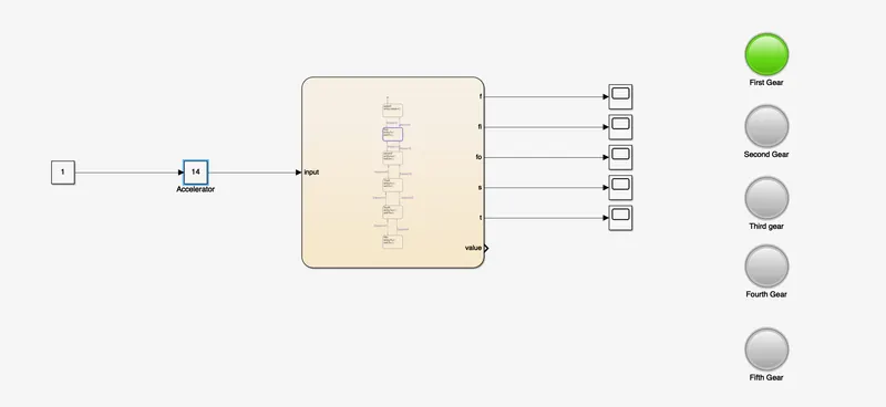
Second gear
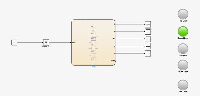
Third gear
Fourth gear
Fifth gear