Week - 4
EV LIVE BATCH 21
- Implement control logic of a “washing machine” using Stateflow as per given sequence:
- If the power supply is available, the system gets activated
- If the Water supply is not available, stop the process & indicate through LED
- Soaking time should be 200s followed by Washing time of 100s.
- Then rinsing happens for next 20s & dryer runs for 50s
After all the processes have completed turn on the finished LED.
Washing Machine basically works with following 4 processes,
Soaking : Includes filling the washing machine's tub with water and mixing in the detergent allowing the load to soak for a while to loosen dirt and begin to remove stains that otherwise might not be cleaned during a normal wash cycle.
Washing : During the wash cycle, the machine uses agitation to mix the water and detergent, as well as to move the clothing around the tub--and against other clothing--to clean the cloths.
Rinsing : Rinsing the load is usually a multi-step procedure. First, the soapy water must be spun from the clothing and wash tub. During the latter minutes of the purging, fresh water is sprayed into the tub to rinse the clothing. The rinse cycle uses intervals of spraying and spinning to force the soapy water and detergent out of the washer. A final stage of agitation with plain water is the last step in rinsing.
Drying : Spinning is necessary for wringing the clothing, getting it as dry as possible before the end of the wash. Oftentimes, water is sprayed into the wash tub to completely rinse the clothing before it's finally spun to its driest point.
So, according to the given conditions, model can be designed creating a stateflow chart,
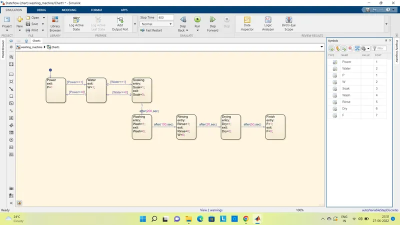
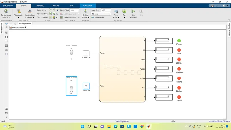
Here, Power and Water are the inputs and its on/off state is given by output as P and W. Other outputs are defined for process of Soaking, Washing, Rinsing and Drying. also, when the washing cycle is over, it will be indicated as Finish state output F.
Conditions are given as per the given conditions to change from one state to the next state. Value 1 means ON and value 0 means OFF. System will start when power=1, and show output as P=1 and will go to next state i.e. water. And if power=0, no further process will happen. similarly with water, for water=1, Soaking process will start otherwise if water=0, process will stop.
Now, when Power=1 and Water=1, only then soaking process will start. It will run for 200 sec, and state will change to washing. After 100 sec of washing, rinsing will start. It will run for next 20 sec followed by drying of 50 sec to complete the process. After complition, Finish value will be F=1.
With this conditions, complete model can be given as,
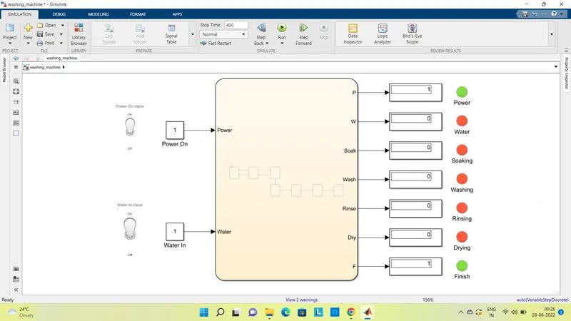
For On state, input value for power and water is given as 1. also a toggle switch is connected to make it ON and OFF i.e. change of state from 1 to 0 or from 0 to 1. LED lamp is incorporated to indicated on-off state showing GREEN if ON and Red if OFF.
Simulation run time is 400 sec, the washing process is complete and indicated as F=1, with green LED on. Power LED will always be on as supply switch is on. Water output is made off while defining the rinsing state, as for drying, water is not required.
We can simulate it for different time to see at what time, what process in going on.
At 200 sec, P=1, W=1, soak=1 - process of soaking
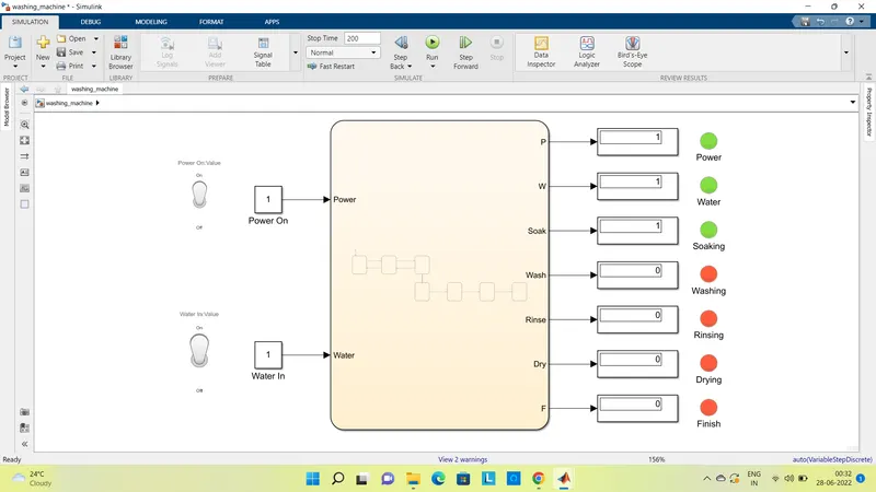
At 300 sec, P=1, W=1, soak=0 - process of soaking is done, Wash=1 - process of washing
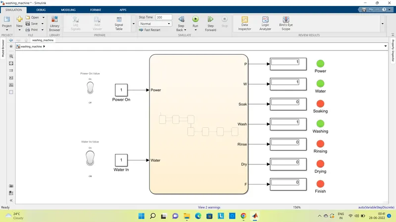
At 330 sec, P=1, W=1, soak=0 - process of soaking is done, Wash=0 - process of washing is done, Rinse=1 - process of rinsing
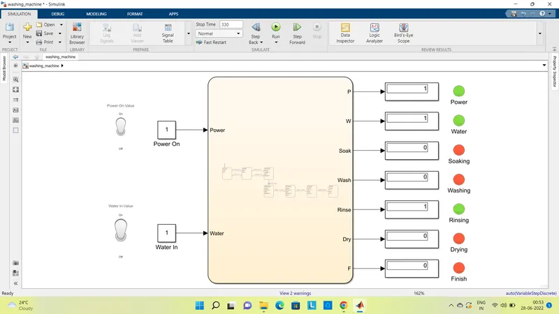
At 350 sec, P=1, W=0 - water is turned off, soak=0 - process of soaking is done, Wash=0 - process of washing is done, Rinse=0 - process of rinsing is done, Dry=1 - process of drying
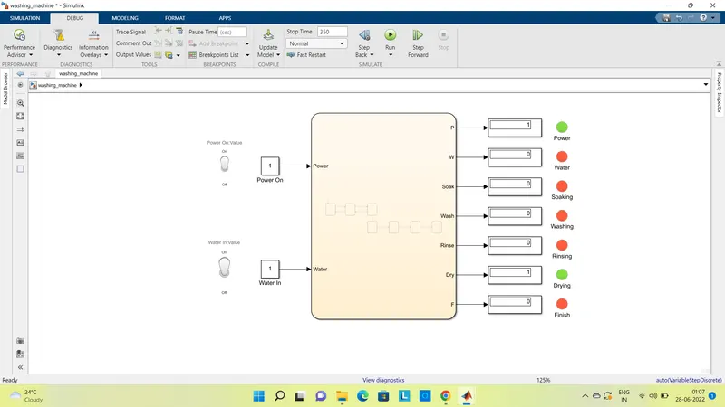
At 400 sec, P=1, W=0, soak=0 - process of soaking is done, Wash=0 - process of washing is done, Rinse=0 - process of rinsing is done, Dry=0 - process of drying is done, F=1 - washing machine process is complete.
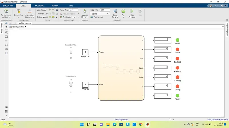
Now, if we switch off the water supply, process will stop right there showing W=0 and will indicate through red LED. And as further process is also stopped, all will show red LED.
2. Make a Simulink chart for the “Gear shift” logic as per below conditions:
Speed Range(kmph) Gear
0 to 15 1
16 to 25 2
26 to 40 3
41 to 60 4
Above 61 5
Give speed input while the simulation is running & display the gear number.
Here, as per given conditions, stateflow chart can be given as,
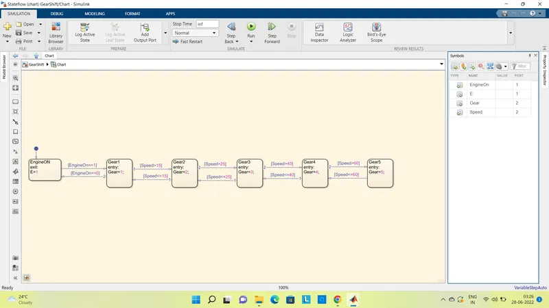
Here, one input is Engine on state, given as E, and if condition EngineOn==1 is satisfied process will go to the next state otherwise process will stop at this stage only. This will be shown with output E=1, greed LED i.e. Engine is on.
Another input is Speed, which will vary with respect to time, accordingly conditions are stated to shift the gears with respect to the speed value at any given instance. The operating gear number will be displayed as output Gear with respect to speed.
The complete model can be given as,
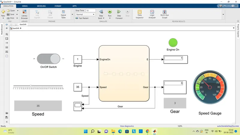
Here, to incorporate Engine On/Off, a slider switch is attached to input engine block which will show one if On, and zero if off. For speed input, a slider is connected to it and also a display to show exact value. Also, a guage is also connected with input speed to have view of acceleration - decelaration. A display is connected to the gear number output so that gear number can be seen for given value of speed.
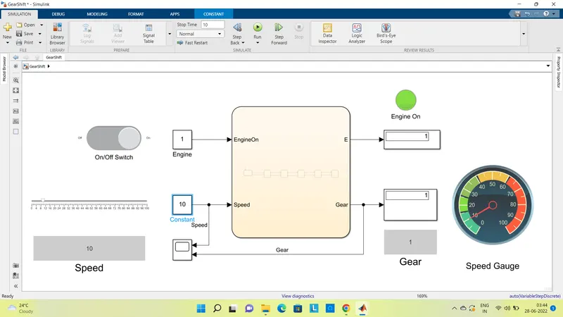
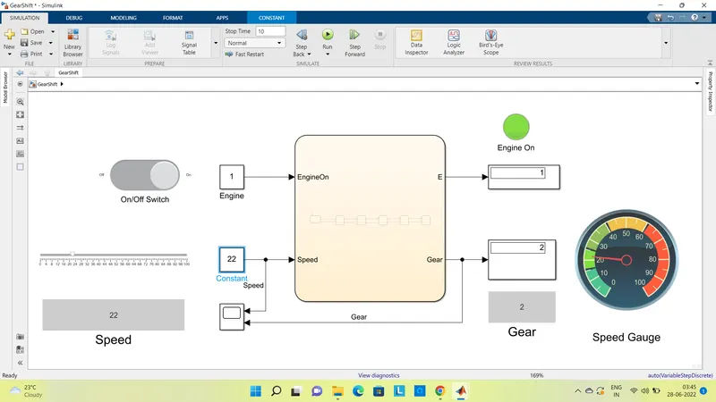
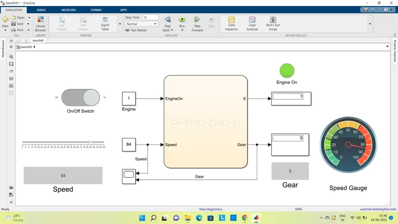
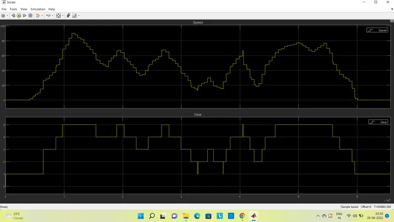
Simulation time can be kept infinite to see running time parameters that for continuous varying value of speed, how gears are getting shifted. The result can be obtained as,