Week - 4
PART 1
AIM
To implement control logic of a washing machine using Stateflow as per given sequence.
THEORY
Washing Machine
A washing machine (laundry machine, clothes washer, washer, or simply wash) is a home appliance used to wash laundry. It is used to wash the various types of clothes without applying any physical efforts. With washing machine you don’t have to rub the clothes with hand or squeeze them to remove the water from them. The washing machine is also called as clothes washer or simply the washer. The washing machine enables you to wash your clothes automatically without having to supervise its operation. All you have to do is put the clothes in the machine and select the wash mode. The washing machine automatically takes in the amount of water and detergent required and it also automatically sets the timer for washing, rinsing and drying as per the selected mode and the amount of clothes.
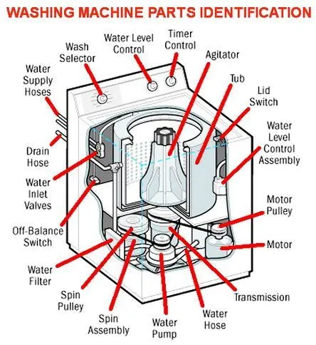
Parts
- An inner drum: This is where you put the clothes when you’re ready to wash. You’ll notice this drum rotates a bit when you touch it and there are a lot of holes punched into the drum. These allow the water to come in and wash the clothes.
- Paddles:These are ridges that lie on the edge of the drum and help move your clothes around while being washed.
- Agitator:These are more common in top load machines and is a paddle in the middle that helps turn the clothes around in the soapy water.
- The outer drum: This is not obvious when you look inside the washer, but there is another drum that holds the water while the inner drum or agitator rotates. This part is completely water tight to prevent your machine from leaking all over the bathroom or kitchen!
- Thermostat and heating element: These control the temperature of the water and heats up the water to the specified temperature.
- Pump: This removes the water from the drum after the wash.
- Programmer: This controls the washing machine through all the steps from washing to rinsing and spin drying.
- Pipes and valves: These allow the water in and out of the washer.
Types
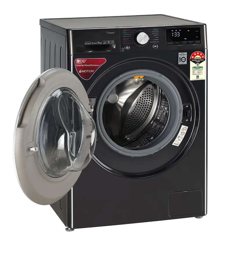
Depending on the position of loading the clothes in washing machine, there are two types of washing machines:
- Top loading washing machine: In this washing machine the clothes are loaded from the top of the washing machine. There is a cover at the top that helps loading and unloading of clothes in the round vessel that perform the function of the washer as well as the rinser and drier in the fully automatic washing machine. The top loading washing machine is preferred by the people who don’t want to bend the body while loading the clothes in the machine. This washing machine is more widely used than the front loading washing machine in many parts of the world.

- Front loading washing machine: In this machine the clothes are loaded from the front side. The studies have shown that the front loading washing machines consume less electric energy, water and detergent and also give better washing results compared to the top loading washing machine.
Depending on the total automatic features available in the washing machine, the top loading washing machines are also classified as:
- Semi-automatic washing machine: This has separate tubs or vessels for the washer and the drier. There are two separate timers that enable setting washing and drying times. To wash the clothes you have to put the clothes in the wash vessel, put sufficient quantity of the water and detergent and then set the timer. After the specified time, the washing machine will stop. You can remove the clothes and dry them in the sun or you can dry them partially in the drier vessel by setting suitable time.
- Fully automatic machine: In fully automatic washing machine there is only one tub that serves as the washer, rinser as well as the drier. Depending on the number of clothes or the weight of the clothes, the machine takes in the sufficient amount of water and detergent automatically and sets the timer for wash and drying automatically. All you have to do is just provide the water connection, put the detergent from time-to-time in its storage space and put the clothes, the fully automatic washing machine does the rest of things automatically.
In the European markets the market share of the front loading washing machines is 90%, while of the top loading washing machines is mere 10%. In contrast, the US has market share of 65% for top loading and 35% for front loading washing machines.
Soak: Soak Function is used to dip clothes in detergent water to remove dirt from the clothes.
Wash: The washing machine is filled with water according to the selected load size, then the clothes and soap are swirled around together.
Rinse: Once the clothes are washed, we need water to remove the detergent from the clothes. This process is called Rinsing. The dirty, soapy water is drained, then the washing machine is refilled and your clothes are rewashed in clean water.
Dryer: It is used to dry the clothes quickly.
BLOCKS USED
- Constant: To generate a constant output value
- Display Block: To show the result or value of the input data.
- Lamp: To displays a color that indicates the value of the connected signal.
- Toggle Switch: To toggles the value of the connected block parameter between two values during simulation.
- Rocker Switch: To toggles the value of the connected block parameter between two values during simulation. For example, we can connect the Rocker Switch block to a Switch block in model and change its state during simulation.
- Chart: It is a graphical representation of a finite state machine
PROCEDURE
- Start
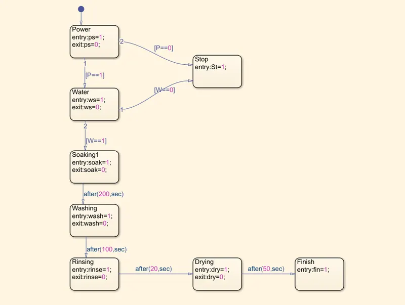
- Create a Chart block then open the chart and make the flow chart as per the given criteria.
- Check for power supply, if condition is true then go for water supply else Stop the process
- Check for water supply, if condition is true then process starts else stop
- Define each processes as per the given conditions i.e Soaking for 200s, Washing for 100sec, Rinsing for 20 sec, Drying for 50 sec and then finish the cycle
- While defining the condition, entry is given by ‘1’ and exit is given by ‘0’, i.e for an on going process it will show 1 as value and for completed process the value will be 0.
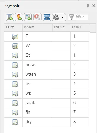
- Define the Inputs and outputs from Symbols
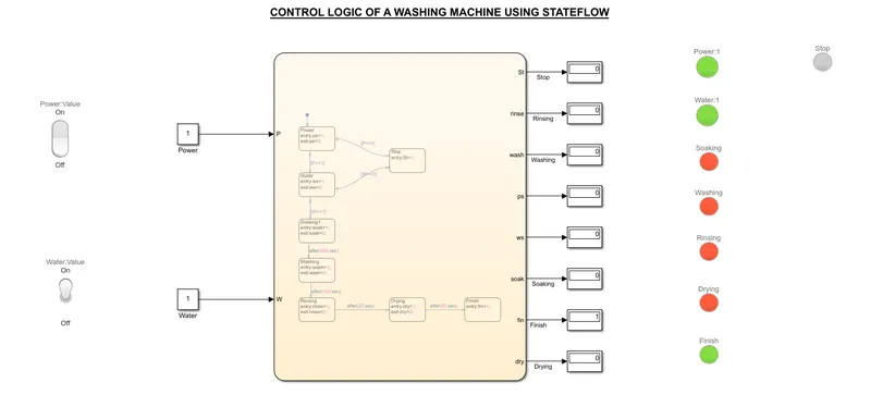
- In the Input, Connect two constant blocks for water supply and power supply respectively
- Connect two switches to these constant blocks such that ‘1’ is set to ON and ‘0’ is set for OFF.
- In Output, each output port is connected to Display block with process and each display block is connected to lamps with 1 as entry and 0 as exit and also with defined colors. Here Green for On/Entry and Red for Off/Exit, Orange for Stop.
- Run the simulation and observe the Results.
- Exit
MODEL
RESULT
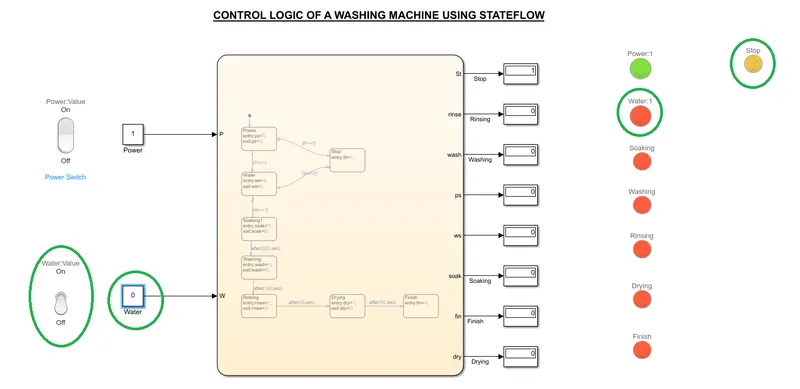
- Non availability of water supply is shown with switch in 'OFF' position. When water is not available, the entire processes will not be carried out and machine will get stopped, which is shown with the help of Lamp
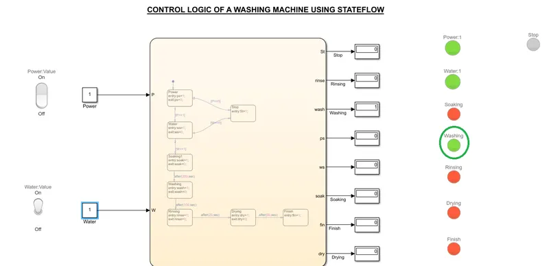
- Washing is going on after Soaking which is shown by the Green Lamp.
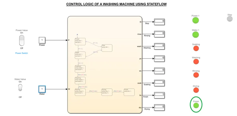
- All the processes have been completed and is shown with Finish in Green Lamp
File Link
https://drive.google.com/file/d/1mJP_ifMHjLQ7vwvjJN6RLmzRAgtsBkqI/view?usp=sharing
CONCLUSION
Control logic of a washing machine using Stateflow as per given sequence has been successfully implemented.
REFERENCE
https://in.mathworks.com/help/simulink/index.html
PART 2
AIM
To make a Simulink chart for the Gear shift logic as per given conditions:
Speed Range(kmph) Gear
0 to 15 1
16 to 25 2
26 to 40 3
41 to 60 4
Above 61 5
THEORY
Gears
A gear is a rotating circular machine part having cut teeth or, in the case of a cogwheel or gearwheel, inserted teeth (called cogs), which mesh with another toothed part to transmit torque. The basic principle behind the operation of gears is analogous to the basic principle of levers. Geared devices can change the speed, torque, and direction of a power source. Gears of different sizes produce a change in torque, creating a mechanical advantage through their gear ratio, and thus may be considered a simple machine The rotational speed, and the torques, of two meshing gears differ in proportion to their diameters. The teeth on the two meshing gears all have the same shape.
Operating in mated pairs, gears mesh their teeth with the teeth of another corresponding gear or toothed component which prevents slippage during the transmission process. Each gear or toothed component is attached to a machine shaft or base component, therefore when the driving gear (i.e., the gear that provides the initial rotational input) rotates along with its shaft component, the driven gear (i.e., the gear or toothed component which is impacted by the driving gear and exhibits the final output) rotates or translates its shaft component. Depending on the design and construction of the gear pair, the transference of motion between the driving shaft and the driven shaft can result in a change of the direction of rotation or movement. Additionally, if the gears are not of equal sizes, the machine or system experiences a mechanical advantage which allows for a change in the output speed and torque (i.e., the force which causes an object to rotate).
Parts Of A Gear
There are a few different terms that you need to know when you are just starting out with gears, as listed below. So that the gears can mesh, the diametrical pitch and the pressure angle must be the same.
- Axis: The axis of revolution of the gear, where the shaft passes through
- Teeth: The jagged faces projecting outward from the circumference of the gear, used to transmit rotation to other gears. The number of teeth on a gear must be an integer. Gears only transmit rotation when their teeth mesh and have the same profile.
- Pitch Circle: The circle that defines the “size” of the gear. The pitch circles of two intermeshing gears must be tangential so that they can intermesh. If the two gears were instead two disks driven by friction, the circumference of those disks would be the pitch circle.
- Pitch Diameter: The pitch diameter refers to the working diameter of the gear, a.k.a., the diameter of the pitch circle. You can use the pitch diameter to calculate how far away two gears should be: The sum of the two pitch diameters divided by 2 corresponds to the distance between the two axes.
- Diametral Pitch: The ratio of the number of teeth to the pitch diameter. Two gears must have the same diametrical pitch to mesh.
- Circular Pitch: The distance from a point on one tooth to the same point on the adjacent tooth, measured along the pitch circle. (so that the length is the length of the arc rather than a line).
- Module: The module of gear is simply the circular pitch divided by pi. This value is much easier to handle than the circular pitch because it is a rational number.
- Pressure Angle: The pressure angle of a gear is the angle between the line that defines the radius of the pitch circle and the point where the pitch circle intersects a tooth, and the line tangent to that tooth at that point. Standard print angles are 14.5, 20, and 25 degrees. The pressure angle affects how the gears touch and how the force is distributed along with the tooth. Two gears must have the same contact angle for meshing
Different Types Of Gears
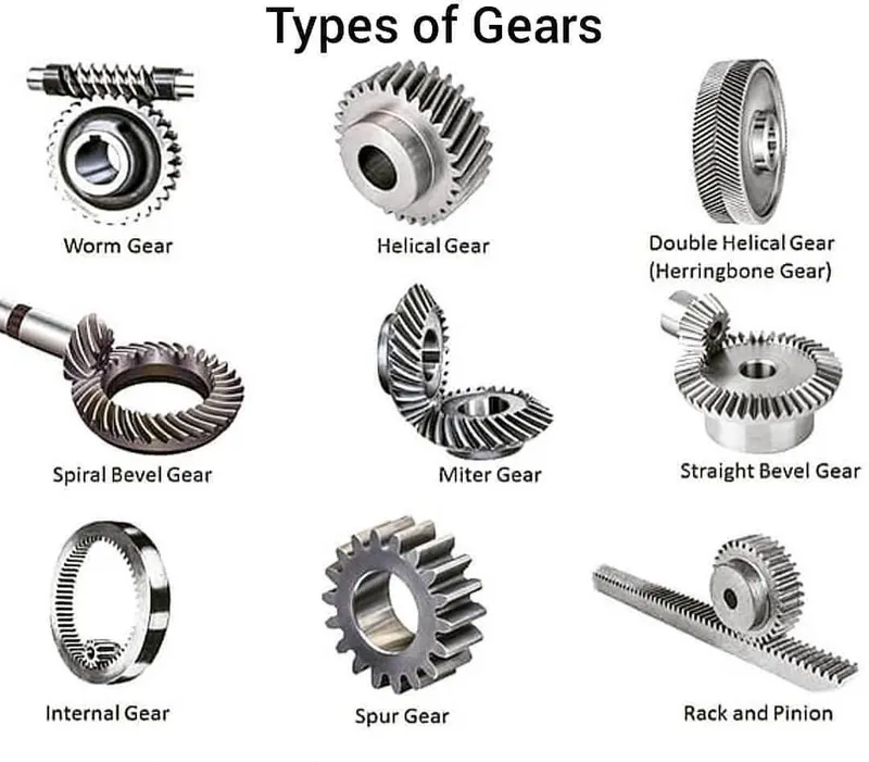
There are many different types of gears such as:
- Spur Gear.
- Helical Gear.
- Gear Rack.
- Bevel Gear.
- Spiral Bevel Gear.
- Screw Gear.
- Double Helical Gear
- Herringbone Gear
- Hypoid Gear
- Miter Gear.
- Worm Gear.
- Internal gear
Advantages
- Gear drives provides large range of speed and torque for same input power, with more accurate timing than a chain system does, less friction loss and noise.
- Gear is positive drive; hence large velocity ratio can be obtained with minimum space.
- Gears are mechanically strong, so higher loads can be lifted.
- Gears are used for transmission of large H.F.
- They are used for transmitting motion over small centre distance of shafts
- They are used for large reduction in speed and for transmission of torque.
- Gears require only lubrication; hence less maintenance is required.
- Using gear systems, we can transmit motion between non-parallel intersecting shafts.
- They are used for positive drive, so its velocity ratio remains constant.
- They have long life, so the gear system is very compact
Disadvantages
- They are not suitable for large velocities.
- They are not suitable for transmitting motion over a large distance.
- Due to the engagement of toothed wheel of gears, some part of machine may get permanently damaged in case of excessive loading.
- They have no flexibility.
- Gear operation is noisy.
Gear Transmission in Cars
All the drive-train components that help transmit the engine power to the wheels are a part of the ‘Transmission’ system. Of which the gearbox is an integral part. These components include the clutch, gearbox, couplings, propeller shaft, axle shafts, and differential. In general, ‘Transmission’ usually refers to the car’s gearbox. However, some car designs integrate the gearbox and differential assembly into a single unit called ‘Transmission’ or ‘Trans-Axle.’
In a car, a transmission, or a gearbox, acts as the medium that transmits power generated by the engine to the wheels via a mechanical system of gears and gear trains. A transmission allows a person to apply power to a vehicle in a controlled manner, without which, the car would not efficiently move. Lower gears in a gearbox provide the required torque to accelerate while higher gears help attain high speed by using the engine’s power more effectively.
Gear Box
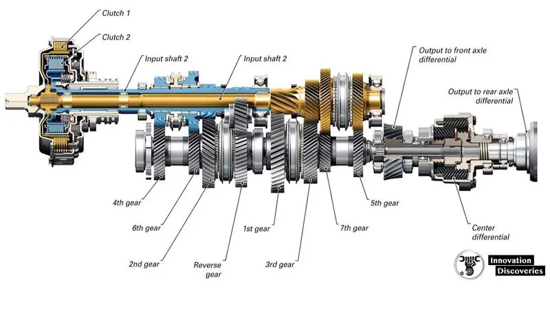
A gearbox comprises various gears, synchronizing sleeves, and a gear-shifting mechanism fitted inside a metal housing. The metal housing, usually made of aluminum/iron casting, accommodates all the gears. The gearbox is a part of the ‘transmission’ system. The gears play an important role in transmitting the engine power to the wheels
A gearbox contains gears of different sizes. It is mainly because of the vehicle’s varying demands for the torque required at the wheels depending upon the road, terrain & load. E.g., if a vehicle is climbing a slope, it needs higher torque than cruising on a straight road.
Furthermore, the first gear is the biggest in a gearbox and provides maximum torque output while producing minimum speed. Hence, the drivers use it when climbing slopes. All the gears between 1st and last gear vary in size, in a decreasing ratio. Thus, it provides a varying combination of pulling ability and speed. So, you could drive the vehicle smoothly without any drop in its acceleration. The gearbox, basically, improves the vehicle’s driveability in all conditions.
BLOCKS USED
- Gauge: To displays the connected signal on a circular scale during simulation. The Gauge block provides an indication of the instantaneous value of the connected signal throughout simulation.
- Slider: To tunes the value of the connected block parameter during simulation. For example, you can connect the Slider block to a Gain block in your model and adjust its value during simulation
- Constant: To generate a constant output value
- Display Block: To show the result or value of the input data.
- Lamp: To displays a color that indicates the value of the connected signal.
- Toggle Switch: To toggles the value of the connected block parameter between two values during simulation.
- Chart: It is a graphical representation of a finite state machine
PROCEDURE
- Start
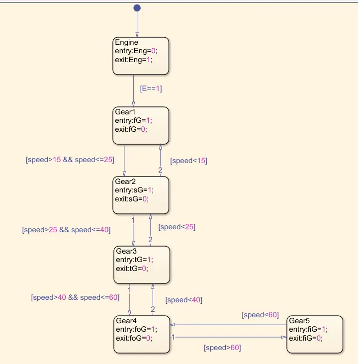
- Create a Chart block then open the chart and make the flow chart as per the given criteria.
- Check for Engine status, if condition is true then go for Gear 1 else Stop and make engine lamp to light red
- Define each gear as per the given conditions of speed.
- While defining the gear condition, entry is given by ‘1’ and exit is given by ‘0’.
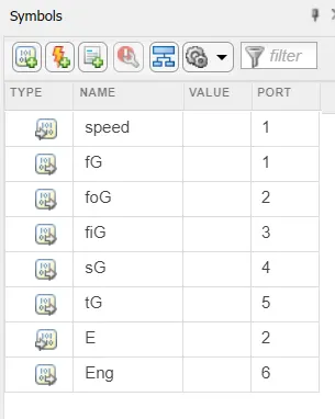
- Define the Inputs and outputs from Symbols
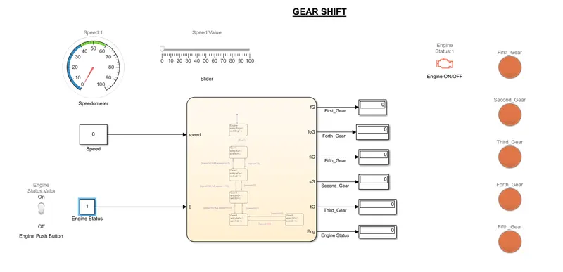
- In the Input, Connect two constant blocks for Engine Status and speed respectively
- Connect a switch to Engine constant block to indicate whether engine is ON or OFF, ‘1’ is set for ON and ‘0’ is set for OFF.
- A speedometer and slider is connected to Speed constant block such that it will shows the speed value
- Each output ports are connected to different displays and lamps, in such a way that 1’ is set for ON and ‘0’ is set for OFF.
- Run the simulation in infinite run time
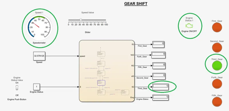
- Adjust the slider to various speed such that speedometer will show corresponding speed values, corresponding Lamp will lights in green and corresponding display block will show '1' in which gear the vehicle is moving. For example if the vehicle is moving in third gear, lamp of third gear will lights up in green, display block corresponding to third gear will show '1' value (shown in result) and all other lamps will be in red and display blocks will show '0'.
- Exit
MODEL
RESULT
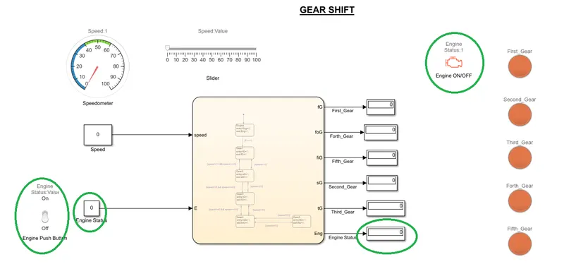
- When Engine is Off: Switch is in Off Position, Value is 0 in Display Block, Engine Lamp is Red in Color.
- When Engine is On: Engine Lamp is Green in Color, Speed 32.5km/h which is shown in Speedometer and Slider, Moving in Third Gear which is shown in the Display Block and respective connected Lamp lightened in Green
File Link
https://drive.google.com/file/d/1FRYzkenrZ6EMvYtsF8hfw02H2T3YAAcE/view?usp=sharing
CONCLUSION
Simulink chart for the Gear shift logic as per given conditions as been successfully made and executed.
REFERENCE
https://en.wikipedia.org/wiki/Manual_transmission