Week - 4
OBJECTIVE 1:-
Implement control logic of a “washing machine” using Stateflow as per given sequence:
- If the power supply is available, the system gets activated
- If the Water supply is not available, stop the process & indicate through LED
- Soaking time should be 200s followed by Washing time of 100s.
- Then rinsing happens for next 20s & dryer runs for 50s
- After all the processes have completed turn on the finished LED
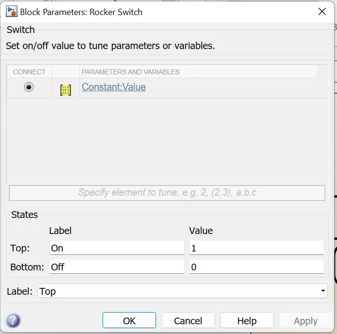
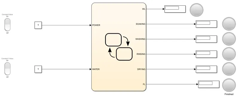
First of all we have to take a 'Chart' in simulink. Then create two input terminal, one for POWER supply and one for WATER supply. Then connect two 'Constant' block with two inputs that will provide the signal(ON & OFF) to POWER and WATER supply. Two 'Rocker Switch' block will also be added with two 'Constant' block that will ON & OFF the signal from 'Constant' block.
Make sure value 1 will be given to on lebel and 0 will be on off lebel as like below-
And create 6 output terminal on the 'Chart'. These terminals will be as
- WL(Worning Light)
- SOAKING
- WASHING
- RINSING
- DRYING
- FL(Finish Light)
All terminals will be connected to a 'Display' block and a 'Lamp' block. If value in 'Display' is 1 then process is completed and if value is 0 then process is not completed. Except WL(Warning Light) all lights will be yellow if process is not complete other wise all lights will be green. So the model will be-
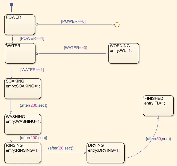
Now we have to go to 'Chart' section to create the logic. First we have to take 8 'State'. First state will be POWER state. From this state two condition will be there. If POWER is 1 then flow willl go to next state WATER, otherwise it will go to a 'Junction' as bypass the value.
If WATER is 1 then flow will go to next state SOAKING, otherwise if WATER is 0 then it will go to a state named WARNING, where a variable WL=1 to on a warning light.
In SOAKING state a variable SOAKING is decleared and value will be 1 that means soaking process is completed. After 200 sec. flow will go to next state WASHING.
In WASHING state a variable WASHING is decleared and value will be 1 that means washing process done. After 100 sec. of washing state flow will go to next state, that is RINSING state.
Inside RINSING state a variable RINSING is created and the value is 1. After 20 sec. flow will go to next state, that is DRYING state.
In DRYING state a variable DRYING is created and the value of this perticuler variable is 1 that means the process have done. After 50 sec. flow will go to FINISHED state, Where a variable FL=1 decleared to indicate that all process have been completed.
So the flow-chart will look like below-
Now if we run the model with below condition then the reasult will be-
- POWER is ON
- WATER supply is OFF
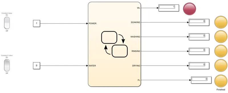
Here signal will go through the POWER state and then WATER state. But in water state logic will not satisfy the WATER==1 condition, because through WATER(input) no signal will pass. So it will satisfy WATER==0 condition and go to WARNING state and red light will ON and stop the process.
Now if
- POWER is ON
- WATER supply is ON
then reasult will be-
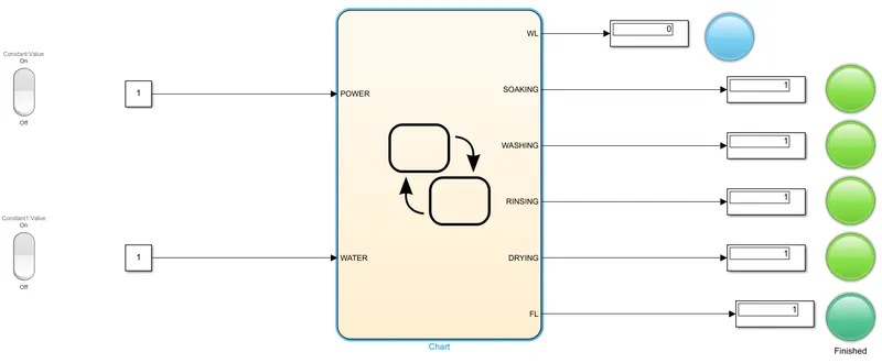
So, with this condition where POWER and WATER both will give signal input 1, all process will complete properly and alllights will turn green.
Model file is given below-
https://drive.google.com/file/d/1qdyIw5KoSCOJof4RlupMhksDaVJZAfJi/view?usp=sharing
OBJECTIVE 2:-
Make a Simulink chart for the “Gear shift” logic as per below conditions:
Speed Range(kmph) Gear
0 to 15 1
16 to 25 2
26 to 40 3
41 to 60 4
Above 61 5
Give speed input while the simulation is running & display the gear number.
To make this model we need 4 block. Those are-
- Chart
- Slider Gain
- Constant
- Display
- Scope
- Circular Gauge
'Constant' block will be connected to input of 'Slider gain' block by which we can change the value when simulation is running. 'Slider Gain' will give the speed value to 'Chart' block. And 'Circular Gauge' will be connected to 'Slider Gain' block to show abetter UI that how speed is changing.
Now a output port have to make on 'Chart' block that will show the Gear number according to speed. 'Scope' block and 'Disply' block have to connect with this Gear number output.
So the model outlook will be-
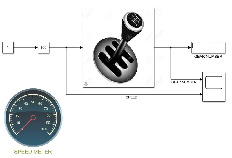
Now inside the 'Chart' block the logic flow have to create as per given condition. We have to take 6 'State' block. First one is 'GEARZERO' where no inside variable declesred. If SPEED>0 then logic will flow to next state that is FIRST.
In FIRST state G value is 1. That means 1st gear will be active. Now if SPEED>15 then logic will flow to next state SECOND and if SPEED<16 then logic will come back to present state.
Now in SECOND state that represents 2nd gear, value of G is 2. If SPEED>25 then logic will flow to next state THIRD and if SPEED<26 logic will come back to present state.
In THIRD state G value is 3. That means 3rd gear will be active. Now if SPEED>40 then logic will flow to next state FOURTH and if SPEED<41 then logic will come back to present state.
Now in FOURTH state that represents 4th gear, value of G is 4. If SPEED>60 then logic will flow to next state FIFTH and if SPEED<61 logic will come back to present state.
So the logic flow will look like-

Now if run the model with infinite time and varry the speed through 'Slider Gain' block when simulation is running the its reasult will be like-
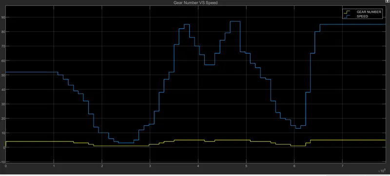
The model file is given below-
https://drive.google.com/file/d/1_c6pZDr1ke1Ua-zsfqrRvxom50H9fPgS/view?usp=sharing