Week - 4
Week – 4: Washing machine and vehicle transmission gear shift control logic implementation
Aim:
- To Implement control logic of a washing machine using Stateflow.
- To Make a Simulink chart for vehicle transmission gear shift logic
Objective:
- To implement the control logic of a washing machine using Simulink stateflow for the given sequence
- The system gets activated when power supply is On.
- When water supply is Off the system stops and indicate through warning lamp.
- When power supply and water supply is available the system runs for the below sequence
- Soaking - 200s
- Washing - 100s
- Rinsing - 20s
- Drying - 50s
- After the above sequence gets completed ‘Finished’ lamp should blink
- To make vehicle transmission gear shift logic using Simulink chart for the below condition
Speed range
(kmph) Gear
0 to 15 1
16 to 25 2
26 to 40 3
41 to 60 4
Above 61 5
Speed should be in the form of live input and gear status need to be displayed.
Simulink Stateflow over view:
Stateflow in Simulink is a control logic tool used to model a decision-making system based in flow charts for the given condition or sequence. It works on the basis of transition of state in a state machine when there is continuous change in the input or a specific
sequence.
In Simulink stateflow system can be incorporated by using the ‘chart’ block in between the Simulink blocks.
The chart will basically receive the input and provide the output based on the design of the state transitions.
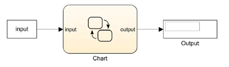
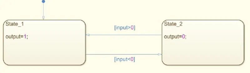
Inside of the chart the main components we use are the state, junction and the transition arrow which is the mean to construct any state flow system. The ‘state’ block represents a state inside of which the specific execution related to state undergoes, in simple it provides the output expected from that state. The state will be switched or changed for the condition set or the sequence using time delays. When the transition occurs the state jumps from on to the other. The transition arrows carry the signal to change state while executing the condition set, it can be a condition or time delay for sequence shifting. The values executed with in the state will be carried to the Simulink system via output port.
Exercise:
Objective-1: To Implement control logic of a washing machine using Stateflow.
A washing machine control logic need to be modelled for the conditions below,
- The system gets activated when power supply is On.
- When water supply is Off the system stops and indicate through warning lamp.
- When power supply and water supply is available the system runs for the below sequence
- Soaking - 200s
- Washing - 100s
- Rinsing - 20s
- Drying - 50s
- After the above sequence gets completed ‘Finish’ lamp should blink
Model construction:
The washing machine control logic system was modelled as below
- Created a new Simulink blank model in the name ‘Washing_machine_control.slx’ with the required configuration parameters.
- A ‘chart’ block was added in to the model.
- Initially 2 states were added for ‘Power On’ and ‘Power Off’ conditions and connected to each other using the 2 transition arrows for both directions, which gives the output for the power lamp to turn it ‘On’ or ‘Off’ also to get the system initiated. The power supply ‘On’ condition provided here is of the value of the minimum voltage requirement of 120V for any house hold washing machines.
- 2 state blocks for water level were added to make decision based on the availability of water supply and to turn on the system to execute the sequence or to stop the system. The condition set to the next transition is based on the availability of water supply, if the value returned from the input is greater than 0 then the transition takes place towards the next state also the true condition output was used to blink the lamp as the start of the system.
- After the decision made in the water supply state returned true, the state transition takes places to execute the sequence of soaking, washing, rinsing and drying for which 4 state blocks were added with transition arrows connected using a junction block to make 2 conditions, one is to check water supply followed by the another condition that is a time delay until it reach the next state.
- A last state to end the process was added which returns the output to blink the finish lamp. With this all the sequence were executed.
- All the 5 sequence states of soaking, washing, rinsing, drying and end are individually connected to a junction block through which it is connected to the water level low state which blinks the warning lamp when water supply is stopped in between sequential state transitions.
- All the 5 sequence states soaking, washing, rinsing, drying, end and the water level low state in turn connected to the power Off state when the power supply stopped in between the transitions.
- 2 input arrays ‘power supply’ and ‘water supply’ was assigned from the transition arrow statement which form 2 input ports in the same name of the array to the chart block.
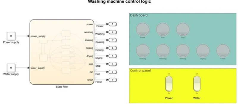
- 8 output arrays in the name power, soaking, washing, rinsing, drying, finish, stop and run were created from the state variables and 8 output ports were formed in the chart block and all the 8 outputs were connected to the ports numbered 1 to 8 from the ‘Sink’ library.
- The 2 inputs to the chart block were connected to 2 constants in the Simulink environment as ‘power_supply’ and ‘water_supply’.
- 2 rocker switches were added to the layout from the ‘Dashboard’ library and connected respectively with the 2 input constant blocks ‘power_supply’ and ‘water_supply’. Where the input value to the ‘power_supply’ constant from the power supply switch was set as 120 which is the operating voltage which enters the chart when the rocker switch is turned On. The input value to the ‘water_supply’ constant was set as 1 when the water supply rocker switch is turned On.
- 8 lamps from the ‘Dashboard’ library was connected to all the 8 output ports to indicate the current state the system processing.
- The run time of the simulation was set as ‘inf’ because this system functions based on the live input values passed through the rocker switches provided in the control panel are live control input provided by the user.
- The Simulink model for the washing machine control logic is given in the below picture.
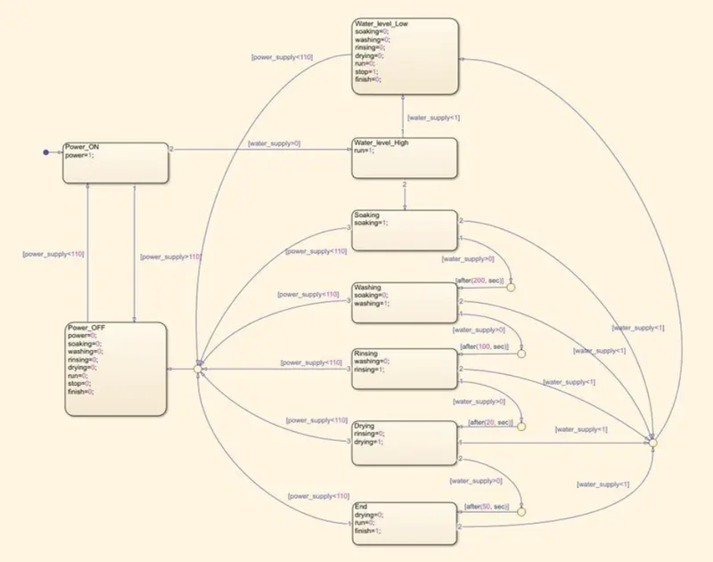
The state flow chart is given as below.
Model function:
The control logic chart consists of 2 inputs and 8 outputs which functions as follows.
- When the ‘Power’ rocker switch from the ‘Control panel’ area is turned On when the simulation is running for infinite time duration the constant value 120 enters the ‘power_supply’ the decision made between power supply ‘On’ and ‘Off’ state by satisfying the condition “power_supply>110” which is the minimum operating voltage required for a washing machine that decides the current state as ‘Power_On’ and returns the output ‘power=1’ which blinks the ‘power’ lamp.
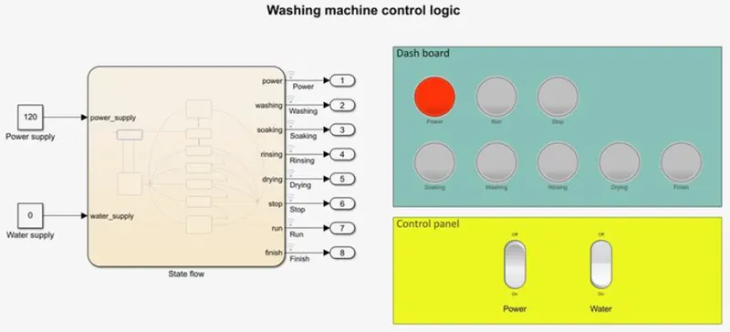
- When ‘Water’ rocker switch is turned On from the ‘Control panel’ the input value to the ‘water supply’ port will be returned as 1 which satisfy the condition of “water_supply>0” that decides the state as ‘water_level_High’ and leaving the ‘water_level_Low’ state. The ‘water_level_high’ state executes and return the output ‘run=1’ which blinks the ‘Run’ lamp and initiate the washing machine sequence by activating the ‘Soaking’ state which returns the output value ‘soaking=1’ which blinks the ‘Soaking’ lamp.
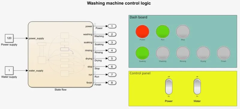
- After Soaking, in the transition arrow which connects the ‘Soaking’ state and the junction block if the condition ‘[water_supply>0]’ is true and it executes the time delay in the next transition arrow between the junction block and the ‘washing’ state ‘[after(200,sec)]’, which sets the current state to ‘Washing’ after 200 seconds. Where the state executes and output ‘soaking=0 and washing=1’ will be returned which blinks the ‘washing’ lamp and turns off the ‘soaking’ lamp.
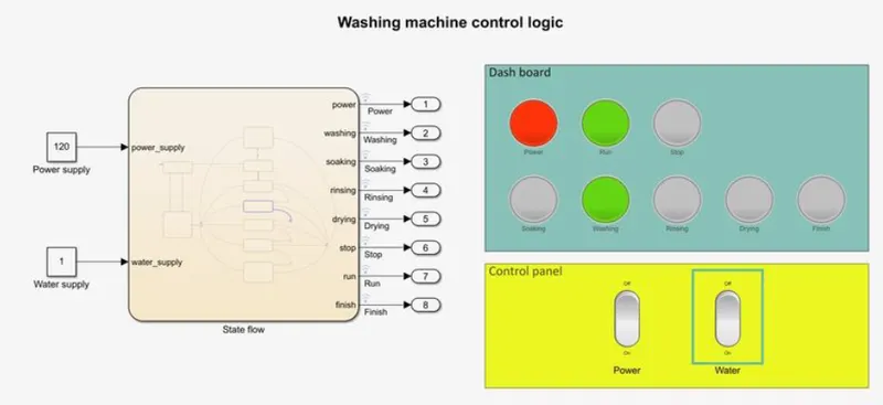
- After washing, in the transition arrow which connects the ‘Washing’ state and the junction block if the condition ‘[water_supply>0]’ is true and it executes the time delay in the next transition arrow between the junction block and the ‘Rinsing’ state ‘[after(100,sec)]’, which sets the current state to ‘Rinsing’ after 100 seconds. Where the state executes and output ‘soaking=0, washing=0 and rinsing=1’ will be returned which blinks the ‘Rinsing’ lamp and turns off ‘washing’ lamp.
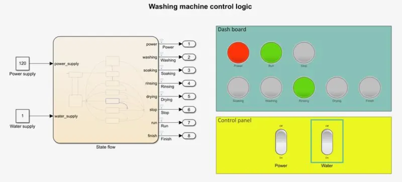
- After rinsing, in the transition arrow which connects the ‘Rinsing’ state and the junction block if the condition ‘[water_supply>0]’ is true and it executes the time delay in the next transition arrow between the junction block and the ‘Drying’ state ‘[after(20,sec)]’, which sets the current state to ‘Drying’ after 20 seconds. Where the state executes and output ‘rinsing=0 and drying=1’ will be returned which blinks the ‘Drying’ lamp and turns off ‘Rinsing’ lamp.
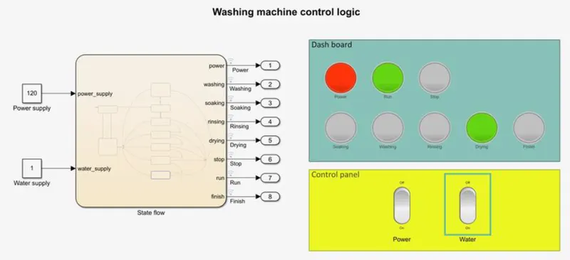
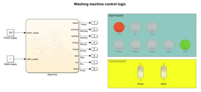
- After drying, in the transition arrow which connects the ‘Drying’ state and the junction block if the condition ‘[water_supply>0]’ is true and it executes the time delay in the next transition arrow between the junction block and the ‘End’ state ‘[after(50,sec)]’, which sets the current state to ‘End’ after 50 seconds. Where the state executes and output ‘drying=0, run=0 and finish=1’ will be returned which blinks the ‘Finish’ lamp and turns off ‘Rinsing’ and ‘run’ lamp.
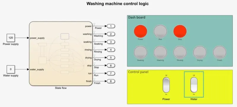
- When the water supply is turned off in any of the state the condition ‘[water_supply<1]’ satisfies in all the transitions arrows that connects all the sequence states to the ‘water_level_Low’ state which executes and output the values ‘soaking=0, washing=0, rinsing=0, drying-=0, finish=0, run=0 and stop=1’ which blinks the ‘Stop’ lamp and turns off ‘Run, Soaking, Washing, Rinsing, Drying and Finish’ lamps.
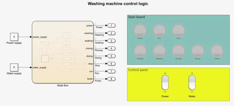
- When the power supply is turned off in any of the state the conditions ‘[power_supply<110]’ (less than minimum operating voltage) satisfies in any of the transition arrows which connects each state to the ‘Power_OFF’ state through a junction block which executes and returns the value ‘power=0, run=0, stop=0, soaking=0, washing=0, rinsing=0, drying=0 and finish=0’ which turns off all the 8 indicator lamps.
Objective-2: To make vehicle transmission gear shift logic using simulink chart for the below condition
Speed range
(kmph) Gear
0 to 15 1
16 to 25 2
26 to 40 3
41 to 60 4
Above 61 5
Speed should be in the form of live input and gear status need to be displayed.
Model construction:
The automatic transmission gear shift sequence is modelled as below
- Created a new Simulink blank model in the name ‘Automatic_transmission_control.slx’.
- A ‘chart’ block was added in to the Simulink model.
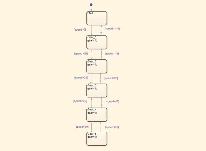
- Inside of the ‘chart’ block the first state added was ‘Start’ which will initialize the sequence.
- ‘Gear_1’ sate was added after the ‘Start’ state and connected with the transition arrows with the condition ‘[speed>0]’ towards ‘Gear_1’ state and ‘[speed==0]’ back to start state.
- ‘Gear_2’ state was added next to ‘Gear_1’ state with the transition arrow condition ‘[speed>16]’ towards ‘Gear_2’ and ‘[speed<16]’ towards ‘Gear_1’ state.
- ‘Gear_3’ state was added next to the ‘Gear_2’ state with the transition condition ‘[speed>25]’ towards ‘Gear_3’ state and ‘[speed<25]’ towards ‘Gear_2’ state.
- ‘Gear_4’ state was added next to the ‘Gear_3’ state with the transition condition ‘[speed>40]’ towards ‘Gear_4’ state and ‘[speed<40]’ towards ‘Gear_3’ state.
- ‘Gear_5’ state was added next to the ‘Gear_4’ state with the transition condition ‘[speed>60]’ towards ‘Gear_5’ state and ‘[speed<60]’ towards ‘Gear_4’ state.
- When any one of the above state is set as the current state it will executes the statement with in the state block at the instance and output the value and store it in the output array named ‘gear’.
- After exiting the chart block an input port in the input array name ‘speed’ and the output port in the output array name ‘gear’ was assigned to the chart.
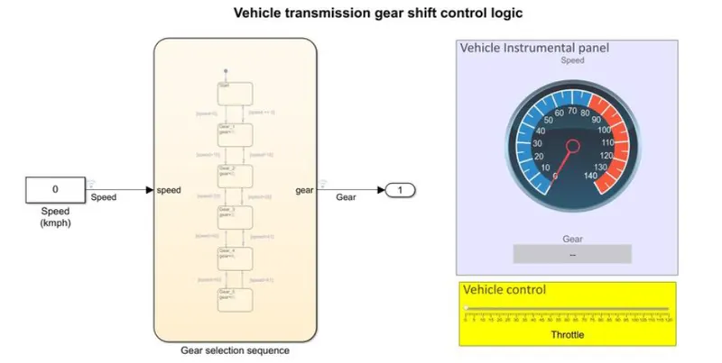
- The input port is connected to the ‘constant’ block and the constant block in turn connected to a ‘Slider’ block from the ‘Dashboard’ library, which was set to provide the maximum input value of 120 which represent the input speed in kmph to the gear shifter system.
- This input slider has been considered as the throttle as this system needs a live input source controlled by the user.
- The input route line was named as speed and was connected to the ‘Custom gauge’ pulled out from the ‘Dashboard’ library and was set to provide the maximum output value of 140 kmph.
- The output port was connected to a pot number ‘1’ added from the ‘Sinks’ library. The route line named as ‘Gear’ was connected to a ‘Display’ which displays the current gear position.
- The run time for the simulation was set as ‘inf’ because the input proving to the system is the live time input provided by the user by controlling the throttle slider.
- The Simulink model for the transmission gear shift control logic is given in the below picture.
- The gear selection sequence chart for the transmission system is given below.
Model function:
The control logic chart consists of 1 input in the name ‘speed’ and one output in the name ‘gear’ which functions as below.
- When the slider representing ‘Throttle’ given in the vehicle control panel is adjusted to a value the current value will be feed to the constant block connected to the chart as the input value, the route line connected to the ‘custom_guage’ shows the speed input to the system and the ‘Display’ shows the current gear selection for the system. The system behavior for different speed conditions are observed as below.
- Speed 0 to 15 kmph, Gear-1 When the input speed value is between 0 to 15kmph from the slider the decision made between ‘Start’ state and ‘Gear_1’ state with the given condition ‘[speed>0]’ towards ‘Gear_1’ state and ‘[speed==0]’ towards ‘Start’ state.The input provided was 10kmph so the condition [speed>0] becomes true and ‘Gear_1’ state was set as current state which executes and provides the output value ‘gear=1’ which is displayed in the ‘Display’ provided in the vehicle instrumental panel.
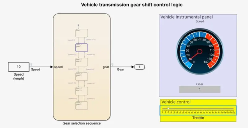
- Speed 16 to 25 kmph, Gear-2
When the input speed value is between 16 to 25kmph from the slider the decision made between ‘Gear_1’ state and ‘Gear_2’ state with the given condition ‘[speed>15]’ towards ‘Gear_2’ state and ‘[speed<16]’ towards ‘Gear_1’ state. The input provided was 20kmph so the condition [speed>15] becomes true and ‘Gear_2’ state was set as current state which executes and provides the output value ‘gear=2’ which is displayed in the ‘Display’ provided in the vehicle instrumental panel.
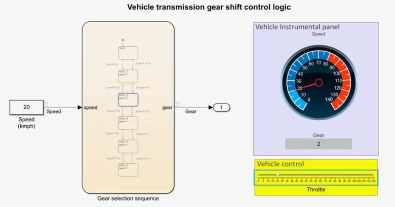
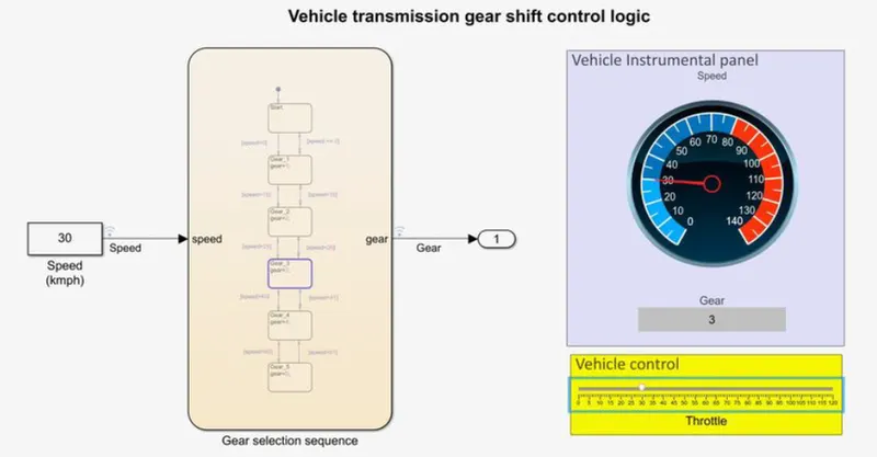
- Speed 26 to 40 kmph, Gear-3
When the input speed value is between 26 to 40kmph from the slider the decision made between ‘Gear_2’ state and ‘Gear_3’ state with the given condition ‘[speed>25]’ towards ‘Gear_3’ state and ‘[speed<26]’ towards ‘Gear_2’ state. The input provided was 30kmph so the condition [speed>25] becomes true and ‘Gear_3’ state was set as current state which executes and provides the output value ‘gear=3’ which is displayed in the ‘Display’ provided in the vehicle instrumental panel.
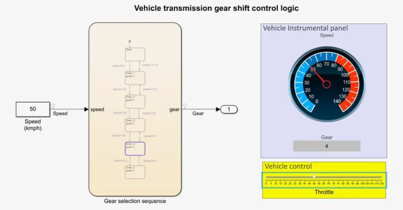
- Speed 41 to 60 kmph, Gear-4
When the input speed value is between 41 to 60kmph from the slider the decision made between ‘Gear_3’ state and ‘Gear_4’ state with the given condition ‘[speed>40]’ towards ‘Gear_4’ state and ‘[speed<41]’ towards ‘Gear_3’ state. The input provided was 50kmph so the condition [speed>40] becomes true and ‘Gear 4’ state was set as current state which executes and provides the output value ‘gear=4’ which is displayed in the ‘Display’ provided in the vehicle.
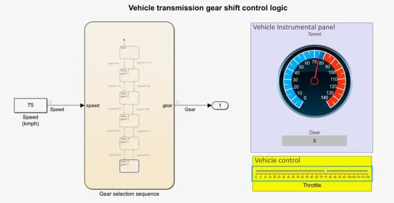
- Speed above 60 kmph, Gear-5
When the input speed value is above 60kmph from the slider the decision made between ‘Gear_4’ state and ‘Gear_5’ state with the given condition ‘[speed>60]’ towards ‘Gear_5’ state and ‘[speed<61]’ towards ‘Gear_4’ state. The input provided was 75kmph so the condition [speed>60] becomes true and ‘Gear_5’ state was set as current state which executes and provides the output value ‘gear=6’ which is displayed in the ‘Display’ provided in the vehicle
Conclusion:
Thus, the control logic for washing machine and vehicle transmission gear control sequence was implemented, executed and output verified.