Week - 4
Aim: To implement the control logic for the washing machine using the state flow and to make a gear shift simulink model using the following input criteria.
Objective of the project:
- To create the logic control for the washing machine using the state flow.
- To create the simulink model using the state flow for the gear shift model for given condtions with variable input (speed) while running.
-
Speed Range(kmph) Gear
0 to 15 1
16 to 25 2
26 to 40 3
41 to 60 4
Above 61 5
-
Body of the content:
1. Control logic for a “Washing Machine” using Stateflow:
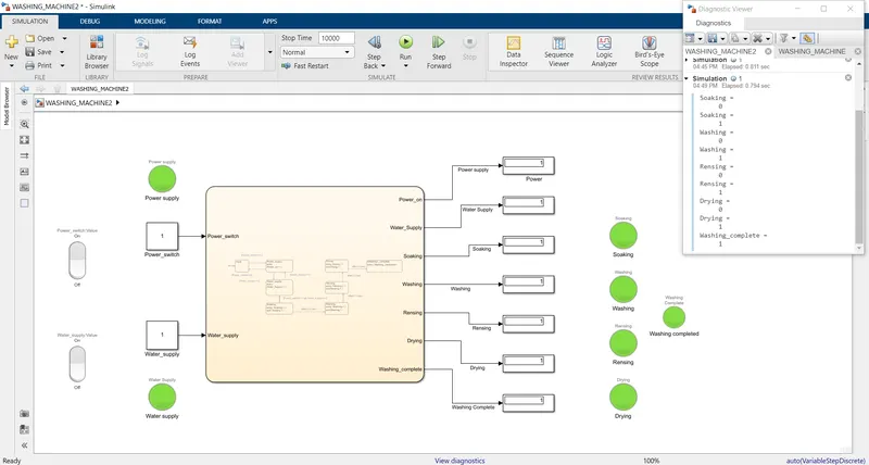
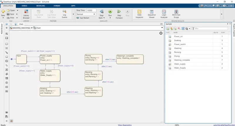
- The above figure shows the state flow of the Washing machine using delay as control logic.
- The blocks used in the process are rocker switches, constant blocks, chart, display and lamps
- The Rocker switchs are used as the switch for the supply of the power and water.
- The input is checked for the ON/OFF condition of the switches and checked whether tpo proceed further or stop.
- If the power and water supply are ON then only the next processes are implemented else they are stopped.
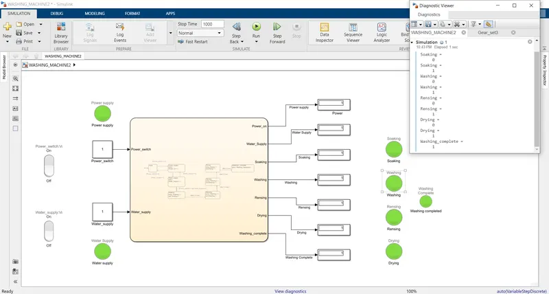
- First the soaking occurs start indicating o and complete representing 1.
- The soaking is done for 200 seconds using 'after(200,sec)'.
- Then washing is followed with the same representing o and 1.
- The washing is doe for 100 seconds.
- Rensing is followed by washing and the duration is 20 seconds.
- At last drying is done for fifthy seconds.
- The completion of the process show as the output if the whole process is completed by the 'Washing completed' state.
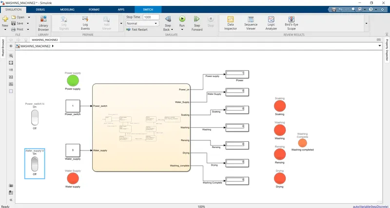
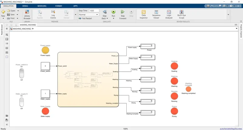
- All the outputs are indicated using the displays and lamps.
- Green shows the process completed and red shows the process is stopped.
2.Simulink model for Gear Shift using logic control and state flow:
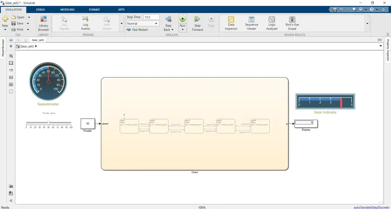
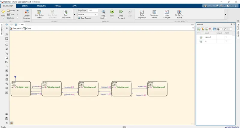
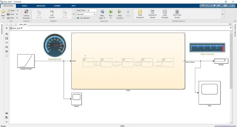
- The above figures represents the block diagram of the gear shift model using the control logic.
- The compenents/blocks used are slider, constant block, chart, circular gauge, display and horizontal gauge.
- The input(speed) is given by slider which is connected with the constant block.
- The input for the variable speed while simulation is done by using the ramp block with 1 slope.
- The time is the input as speed for the ramp block.
- The control logic is the speed (kmph) which decides the transition of the gears.
- The state flows works on the input as speed is compared with the condition in the from first to last which ever condition is satisfied the gear(state) is shifted to the respective state gear.
- Suppose the speed input is 50 kmph the input is checked with the predefined conditions and when the condition is satisfied the state characteristics i.e. respective gear number is given as the output.
- The input and the output of the chart are defined using the symbols pane.
- To view the output the display and the horizontal guage is used which displays the gear with respect to the speed.
- The speed in kmph is displayed with the help of circular gauge.
- The gear are defined as the states in the chart with the specified range of the speed.
Results:
- Washing machine
- When power and water supply are on.
- When Power is on and water supply is off.
- When power and water supply are off.
- Gear shift:
- Gear/ state transition for the 50 kmph:
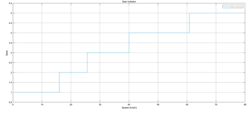
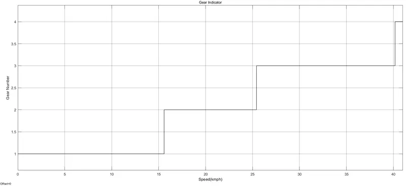
- Variable throttle input from 0-80 Kmph (80 sec):
Conclusions:
- The control logic using state flow for the washing machine is implimented and the desired output is obtained and the results are shown above.
- The simulink chart for the gear shift model is successfully executed for variable speed as input with respect to the speed specified.