Week - 4
1. Implement control logic of a “washing machine” using Stateflow as per given sequence:
- If the power supply is available, the system gets activated
- If the Water supply is not available, stop the process & indicate through LED
- Soaking time should be 200s followed by Washing time of 100s.
- Then rinsing happens for next 20s & dryer runs for 50s
After all the processes have completed turn on the finished LED
Principle of Washing Machine:
Working principle of washing machine base on centrifugation. Washing Maching spin with 800 to 1600 rpm it help to leave dirt and sope from cloths. Also its help for partially drying the cloths. These process done with the help of centrifugal force. The washing machine consists of centrifugal for this process.
Flowwing are the steps of wash cloths in washing machine.
1) Soaking
2) Washing
3) Rinsing
4) Drying
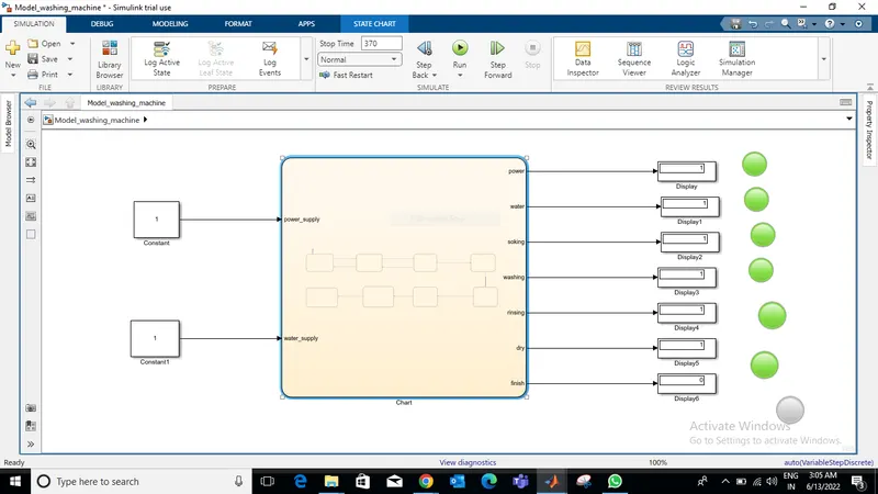
Simulink Model:
State-Flow:
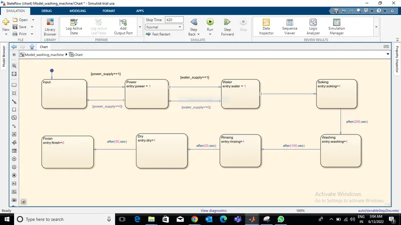
In above simulink model showing two inputs which are, one of them is power and another one is water supply. as per the mention condition model run throug all procedure such as Soaking, Washing, Rinsing, Drying.
Above mention flow-State for better understanding.
*There is an error in model I am able to get that, Model is running but its not running with respect to time, it not showing actual output with respect to time please check it comment what I miss, it will help me to correct the model.
2. Make a Simulink chart for the “Gear shift” logic as per below conditions:
Speed Range(kmph) Gear
0 to 15 1
16 to 25 2
26 to 40 3
41 to 60 4
Above 61 5
Give speed input while the simulation is running & display the gear number.
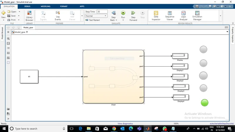
Simulink Model:
State-Flow:
Result Image:
1st Gear:
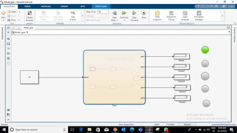
2nd Gear:
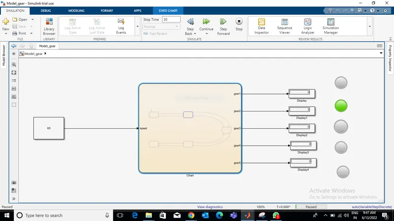
3rd gear:
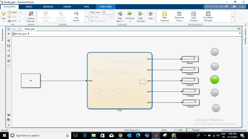
4th Gear:
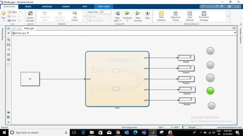
5th Gear:
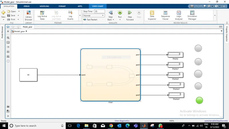
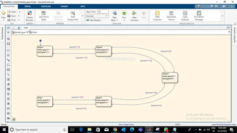
In above simulink model, Input provided in terms of speed. The gear change according to speed condition and light blink. For better understanding simulink model is attach below.
abive State flow image give better understanding of changing gear on specific speed.