Modelling of EV using MATLAB and Simulink
Title: Modeling of Electric Vehicle using MATLAB/Simulink
Aim: To model a most simple electric vehicle using powertrain block set.
Objective:
To model most simple and low run time vehicle model using individual component model.
To check out performance parameter: Speed, SOC%, Current, etc with various drive cycle.
Theory:
Electric Vehicle is new trend came in industry which is ecofriendly, low maintenance, and long lasting. Electric vehicles (EVs) offer an opportunity to replace fossil fuels in the transport sector. Electrification of the transport sector can also bring benefits in terms of increased energy efficiency and reduced local pollution. All electric vehicles run on electric energy through battery. Electric vehicle have an Electric Motor instead of IC engine. In EV the motor is drive with the help of electric energy which is provided by battery. On daily bases we need to charge the battery, in market we can find good batteries with high rating to drive the motor and EV.
Electric cars function by plugging into a charge point and taking electricity from the grid. They store the electricity in rechargeable batteries that power an electric motor, which turns the wheels. Electric cars accelerate faster than vehicles with traditional fuel engines – so they feel lighter to drive.
In full electric mode, an electric car produces zero tailpipe emissions, dramatically lowering smog and greenhouse gas emissions even when considering electricity generation. Cleaner cars mean cleaner air and better health.
Blocked Used:
Drive Cycle: It is velocity with respect to time which feed to model. We can customize our drive cycle also.
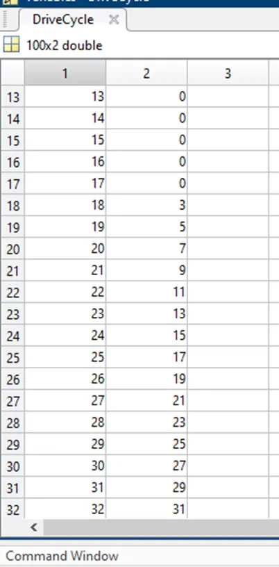
Customized Drive Cycle
Controlled PWM Voltage: The Controlled PWM Voltage block represents a pulse-width modulated (PWM) voltage source.
H-Bridge: The H-Bridge block represents an H-bridge motor driver. The block has the following two Simulation mode options: PWM — The H-Bridge block output is a controlled voltage that depends on the input signal at the PWM port.
Battery: It is a source for the model.
DC Motor: This block is used in the DC Motor Position.
Current Sensor: It is current measurement block in model.
Longitudinal Driver: A parametric longitudinal speed tracking controller for generating normalized acceleration and braking commands based on reference and feedback velocities.
Tire: Represents the longitudinal behavior of a highway tire characterized by the tire Magic Formula. The block is built from Tire-Road Interaction (Magic Formula) and Simscape Foundation Library Wheel and Axle blocks. Optionally, the effects of tire inertia, stiffness, and damping can be included.
Vehicle Body: Represents a two-axle vehicle body in longitudinal motion. The block accounts for body mass, aerodynamic drag, road incline, and weight distribution between axles due to acceleration and road profile. The vehicle can have the same or a different number of wheels on each axle. Optionally include pitch and suspension dynamics or additional variable mass and inertia. The vehicle does not move vertically relative to the ground.
Simple Gear: Represents a fixed-ratio gear or gear box. No inertia or compliance is modeled in this block. You can optionally include gear meshing and viscous bearing losses.
Simulink Model:
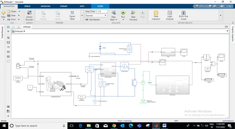 Fig. 1 Simulink Model of EV
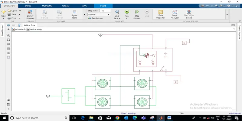 Fig. 2 Vehicle Body
Result:
As we can see the all result screen shot after simulating vehicle for 110sec with customized drive cycle. Fig. 1 showing the input velocity and the feedback velocity (Vehicle velocity). If we check with vehicle velocity it’s not matching with the input velocity because of few losses.
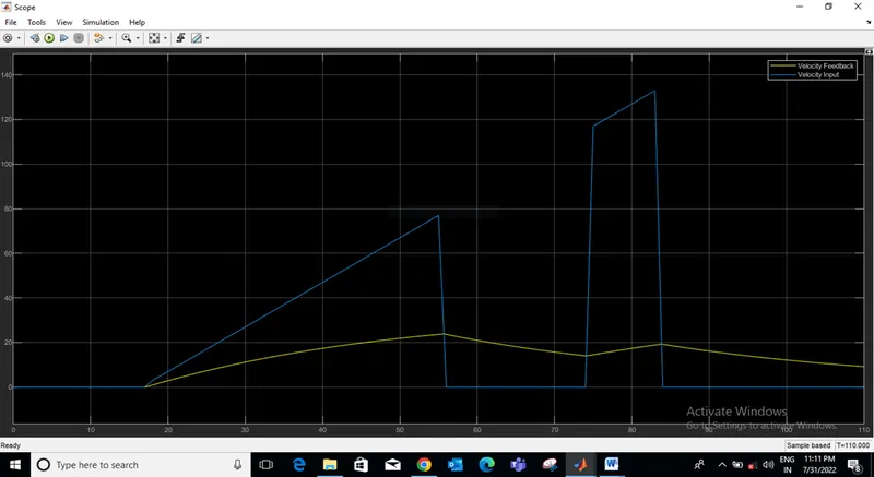 Fig. 3 Input and Feedback Velocity
In below fig. 2 we have SOC% after simulating vehicle. For first 16-18sec the SOC level is constant because the vehicle has zero velocity but after 16-18 sec SOC start decreasing because vehicle start moving with increasing speed with respect to time and SOC start decreasing till 66sec after that SOC increase because of regenerative braking. In interval 66-74sec SOC increase because our vehicle velocity decrease to zero in that specific interval because of regenerative braking battery start charging and SOC increase.
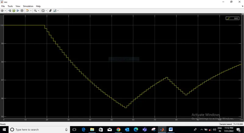 Fig. 4 SOC%
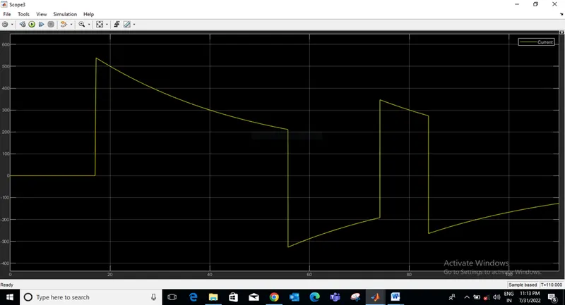 Fig. 5 Current
Here is the Screen shot of distance cover by vehicle in 110sec with customized drive cycle.
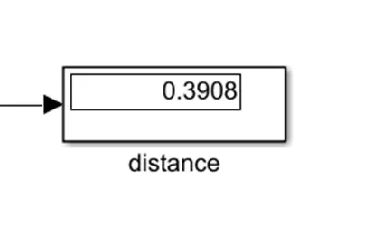
Fig. 6 Distance Covered
Conclusion:
With Customized drive cycle in 110sec 0.3908km distance covered by vehicle. SOC result concludes that, regenerative braking charge the battery.