Week - 4
Report-1
Given data
- Check electric supply condition
- Then water supply condition
- Socking -200 sec (0-200sec)
- Washing-100sec(200-300sec)
- Rinsing -20 sec(300-320sec)
- Drying -50sec(320-370sec)
- completed
Components of Washing machine
The important component are inner drum, the valve, the pump, and the heating elements.
Working of the washing machine
- Put the clothes in the machine and detergent either in the tray or directly to the machine.
- Switch on the power and set the program of time and type of wash.
- The programmer opens the water supply valve and then fill the water up to the level and if the water temperature measured by thermostat is low then heating elements work in order to get hot water.
- When the water up to the level then the valve close.
- When the incoming water attain the temperature, the inner drum starts to rotate in to and front direction.
- The detergent pulls out the dirt from the cloths and trap in the water
- After completing the wash, the programmer opens the drain valve, then switch on the pump to help empty the water away
- Then the program opens the clean water valve
- Then the programmer rotates the drum in to and front motion again with clean water and then drain, this step continue until the soap get rid out.
- When the clothe rinsed the programmer rotates the inner drum with a speed of 130km/hr so that the cloth get dry
- And if also the wet clothes are there, we use heating elements to get heat and dry
Block used
- Constant block
- State flow chart block
- Display block
- Lamp
Control logic of the washing machine
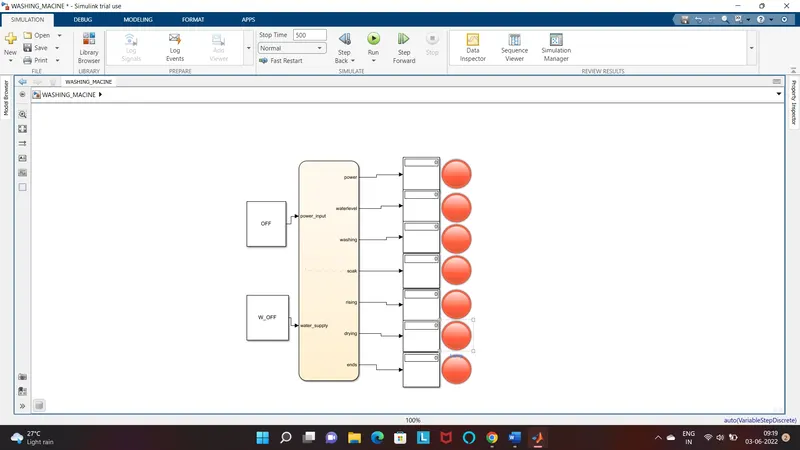
To create this control system in Simulink insert the chart and create the logic system using state flow.
In this control logic the input power is applied to ON the machine and the power supply is flow to the other system. The conditions are applied to move other sequence of operation in the state flow
Then the water supply is executed when the power is ON, so entry and exit are assigned as the value for 0 to 1. While the condition Is not ok then it return back to the initial state
This process is applied for each flow and time of working in each operation are initiated by sec that are given in the question
State flow of the washing machine are the follow
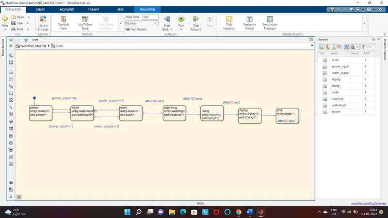
Now assign the input and output date using the symbol pane as shown at the right corner
And assigned the input values of the steady flow sequence of operation is initiated to identify the working division. Constant block is created to give an input power value of the system.
And a constant block is created for the input of the water supply and the value as 1 to on water and to run the washing sequence.
RESULT
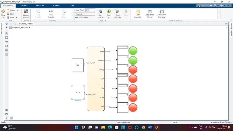
When the power is ON
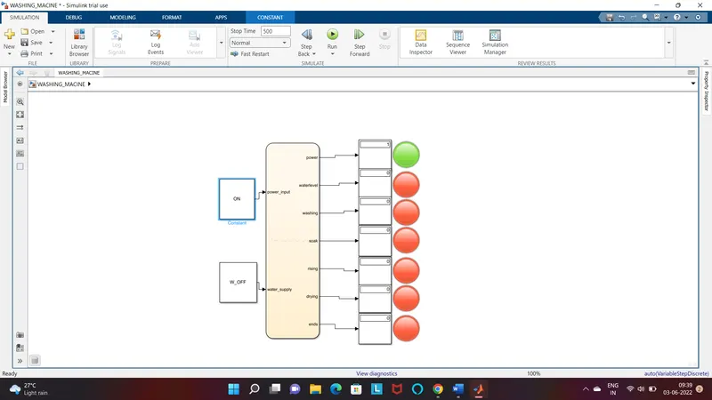
When the power ON,water supply ON,and time durartion of 200sec
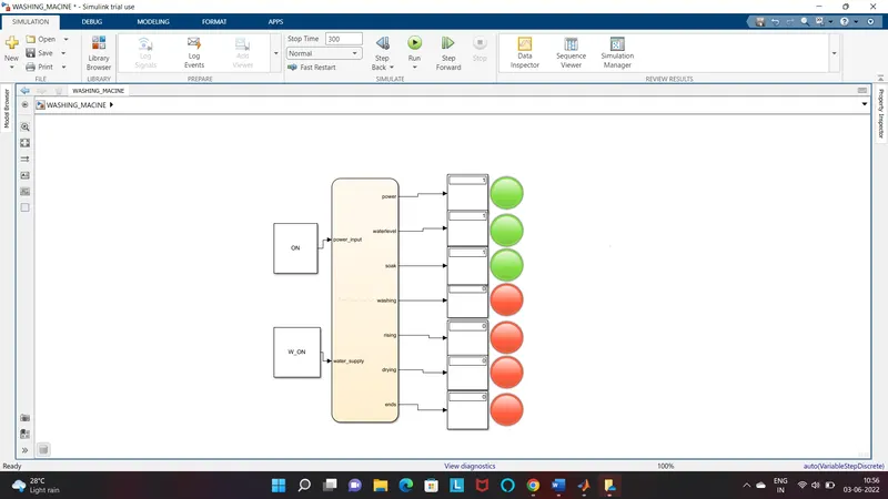
when time duration is 300sec(completed soaking stage)
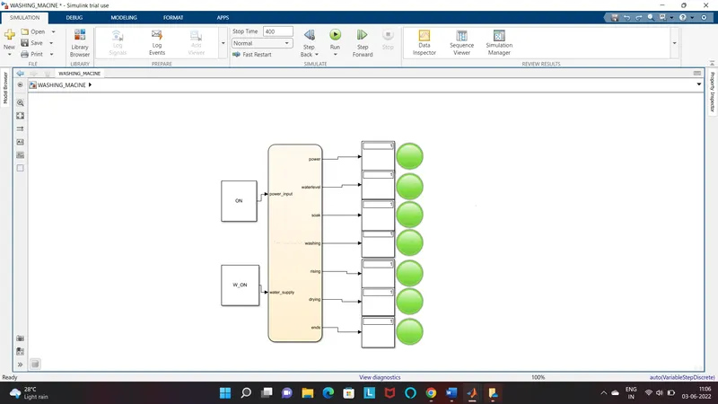
When time duration is 400sec
REPORT- 2
Given data
1st gear-(0-15kmph)
2st gear-(15-25kmph)
3st gear-(25-40kmph)
4st gear-(40-60kmph)
5st gear-(60kmph and above)
A conventional 4-5 speed manual transmission is often the standard equipment in a modern base model vehicles, with 4 speed being more common in non-passenger vehicle such as pick up trucks and light commercial vehicle. Higher end vehicles such as sports care and luxury cares are often usually equipped with a 6-speed transmission for the base model.
Working of the gear shift is when we push the shifter towards the desired gear the gear looks into the man shaft and rotates it. Thus, the main shaft rotates at the speed of engaged gear and provide the output as per the gear’s ratio. Shifting of gears means going from one gear to another by sliding or clicking the shifter. downshifting means going to lower gears and decreasing the speed and upshifting means going to the higher and increase the speed.
Block used
- Constant
- Slider gain
- Lamp
- State flow chart
- Scope
- Circular Gauge
CONTROL LOGIC OF GEAR SHIFTING
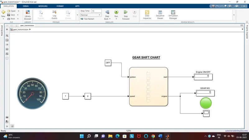
Explanation
- At the initial point ,the slider is at 0
- Assign the input value and output using the symbol pane
- First need to give input to start the engine and then after only the flow goes to next
- When we increased the speed the input is given to the state flow chart where it check the input speed and display the gear number.
- According to the given data
Stateflow chart of gear shift
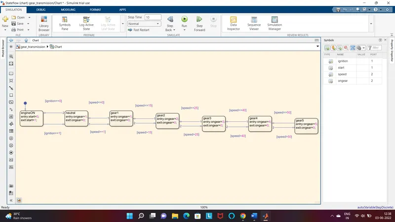
Then from the output the corresponding gear will diplay and the lamp blows ,the lamp colour code for the corresponding speed is as follow
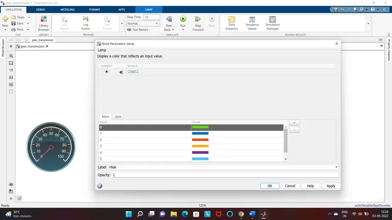
The green represents the neutral gear and other colour represent corresponding gears respectivily
RESULT
Neutral position stimulation
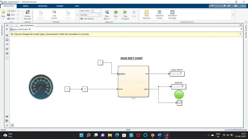
First Gear stimulation
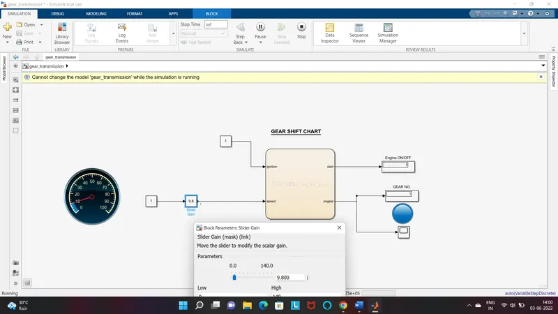
Second Gear stimulation
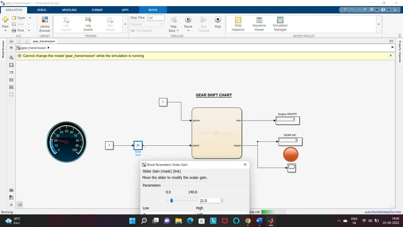
Third Gear stimulation
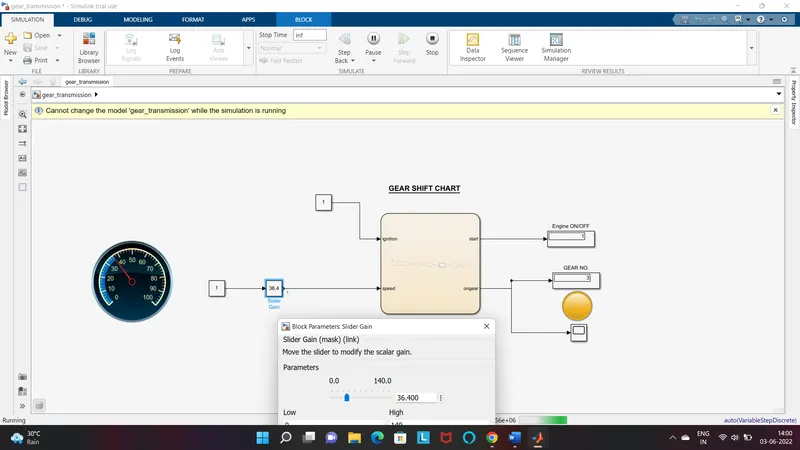
Fourth Gear stimulation
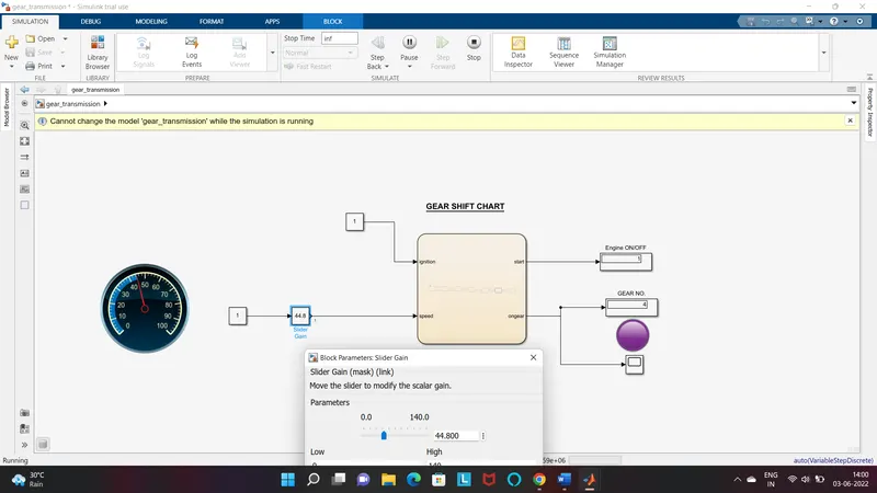
Fifth Gear stimulation
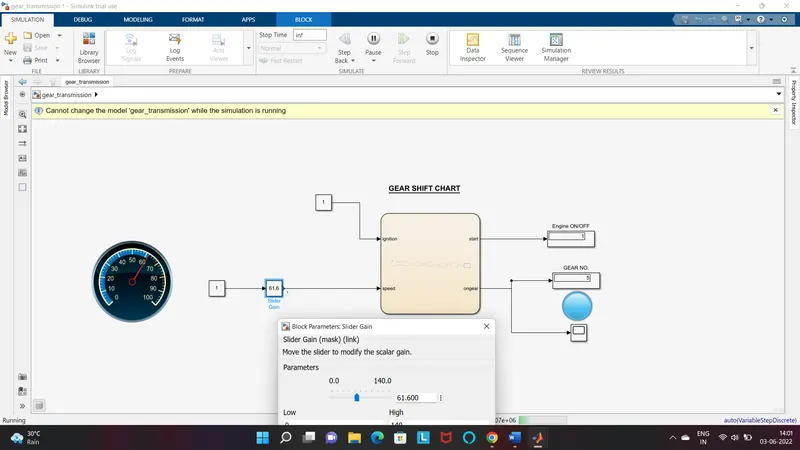
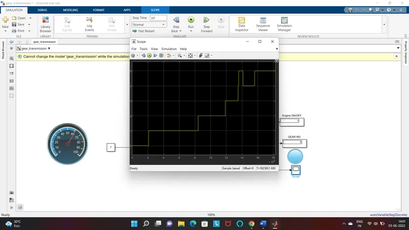
Scope Stimulation Result