Week - 4
Objective:
- Implement control logic of a “washing machine” using State flow as per given sequence:
- If the power supply is available, the system gets activated
- If the Water supply is not available, stop the process & indicate through LED
- Soaking time should be 200s followed by Washing time of 100s.
- Then rinsing happens for next 20s & dryer runs for 50s
After all the processes have completed turn on the finished LED
- Make a Simulink chart for the “Gear shift” logic as per below conditions:
Speed Range(kmph) Gear
0 to 15 1
16 to 25 2
26 to 40 3
41 to 60 4
Above 61 5
Give speed input while the simulation is running & display the gear number.
- Implement control logic of a “washing machine” using Stateflow as per given sequence:
- If the power supply is available, the system gets activated
- If the Water supply is not available, stop the process & indicate through LED
- Soaking time should be 200s followed by Washing time of 100s.
- Then rinsing happens for next 20s & dryer runs for 50s
After all the processes have completed turn on the finished LED
Solution:
A Washing machine is a machine used to wash various types of clothes without applying any physical effort. With a washing machine, you don’t have to rub the clothes with hand.
A washing machine (laundry machine, clothes washer, washer, or simply wash) is a home appliance used to wash laundry. The term is mostly applied to machines that use water as opposed to dry cleaning (which uses alternative cleaning fluids and is performed by specialist businesses) or ultrasonic cleaners. The user adds laundry detergent, which is sold in liquid or powder form, to the wash water.
Stages of washing machine:
Let us undergo the stages of washing machine which in turn help you to undergo better and pick the option depending on the basis of your need successfully
- Prewash
- Washing
- Rinsing
- Spinning
Learning these things essential to pick the right option at the right time.
Prewash
The pre wash cycle is a short wash cycle that fills the wash tub with water, agitates, and spins the water out.
Washing
In washing machine is filled with water according to the selected load size, then the clothes and soap are swirled around together
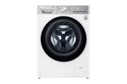
Rinsing
The option called rinsing is known for the multi-talented option. During this particular cycle is on the flow, the soapy water taken from the clothes. And all the fresh or pure water is sparkled to the clothing available in the tub. This particular rinse option held responsible for taking soapy water out of the washer without facing any kind of difficulties.
Spinning
Spinning is done to dry the entire clothes before getting to the end of the actual wash cycle And these several washing machines are going to be spun at different speeds. In turn, the speed of one particular spin is calculated in revolutions per minute (rpm) respectively. This indicates the speed of the spin extracting the whole amount of water from the clothes making it dry very well.

These are the different cycles done by each model available in the indian market. Accordingly, the machine coming with these factors enhances high performance. All the things one should aware of these options and must pick the right one at the right time. For any doubts, mention a single comment in the following rectangular section.
So that we help you understand the terminology much better comparatively. Thank you. If you like to learn more interesting things related to washing machines, keep in touch with the best washing machine irrespective of time and place
Modeling of Washing machine in Simulink these are the following things we need for modeling the subs system of washing machine logical block settings:
- Toggle switch
- Constant
- State flow chart
- Lamps
- Display
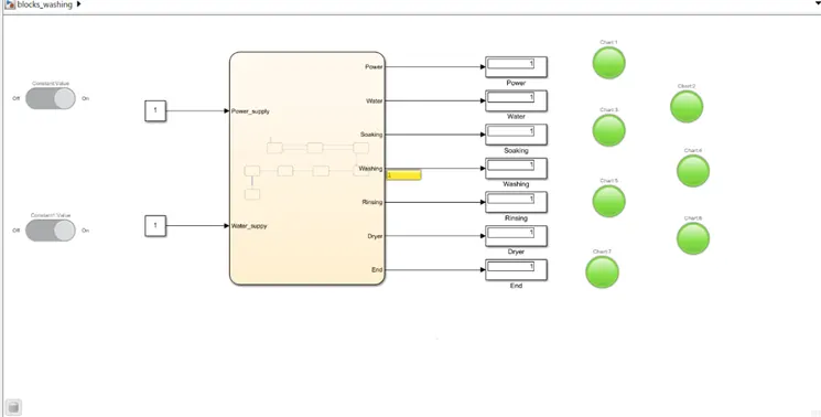
Now the following steps involves in the process
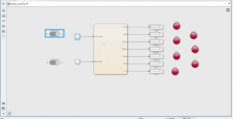
- Switch off and non operational:
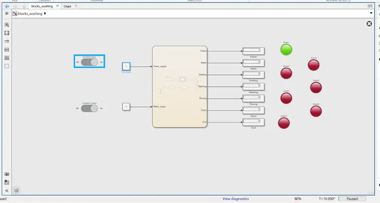
- Power on :
- Water supply on:
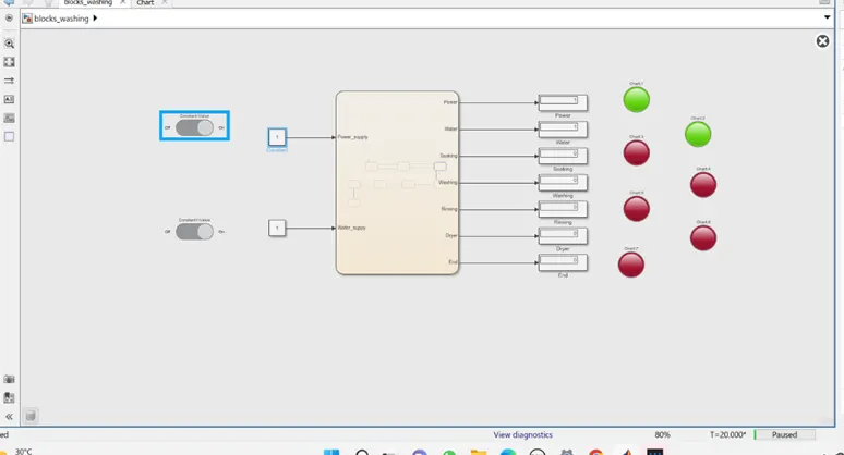
- Soaking:
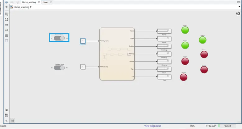
- Washing on:
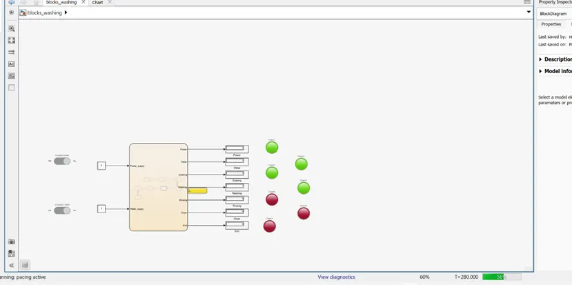
- Rinsing :
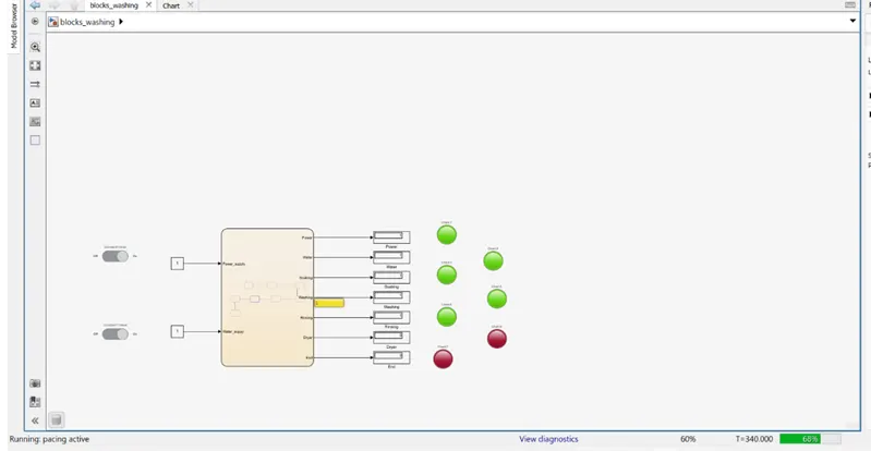
- Drying :
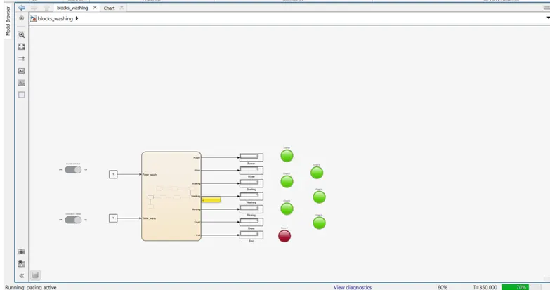
- END Process:
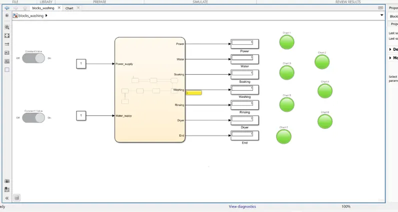
Flow chart:
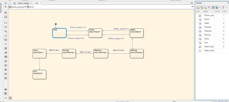
Just according to given data we execute the challenge.
- Make a Simulink chart for the “Gear shift” logic as per below conditions:
Speed Range(kmph) Gear
0 to 15 1
16 to 25 2
26 to 40 3
41 to 60 4
Above 61 5
Give speed input while the simulation is running & display the gear number
Solution:
The Transmission operating mechanism:
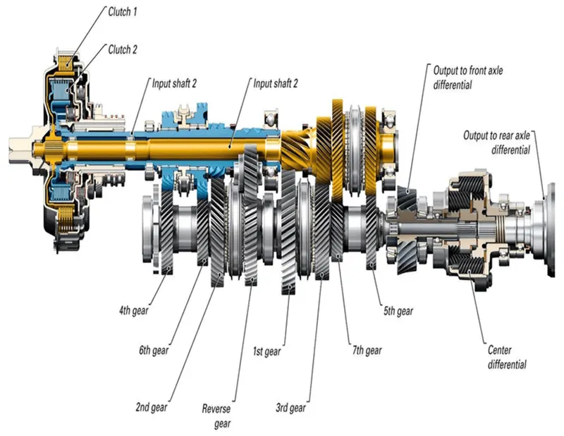
To affect a gear change, selecting first gear, for example, the driver depresses the clutch, disengaging the input shaft. Using the shift lever the driver selects the first gear, and the linkage moves the shift fork to connect the 1st 2nd Iocking collar with 1st gear, locking it to the output shaft. Now, when the clutch is release, engaging the input shaft, the output shaft turns because 1 gear is locked to the output shaft by the locking collar.
As the driver speeds up, selecting 2nd gear simply involved repeating the process, but moving the shift lever to2nd gear. The shift shaft moves the shift fork to disengage 1 gear and engage 2 gear Releasing the clutch engages the input shaft again, this time routing power through 2nd gear. Changing to 3 gear involves using a second shift linkage, shift fork, and locking collar, this one between 3rd and 4th gears.
Because the countershaft and output shaft turn at different speeds, moving from 1st to 2nd gear, trying to engage a higher gear while the vehicle is moving slower would be like trying to turn the shaft at two different speeds, which is impossible. Synchronizer rings are like tiny clutches, using friction to bring the locking collar and the gear to the same speed, at which point they easily mesh and power can be reapplied.
Process:
- The Stateflow chart is having inputb which are speed . The speed input is connected with a constant named Accelerator speed
- Speed conditions are defined for each block. When it exceeds the speed condition the process flows to the next block. All the conditions have been assigned to each block.
- in the output there is 5 outputs each contain 5 display and 5 lamps.
- The 'GEAR INDICATOR display block displays the exact gear at which the vehicle is running. Five lamps have been connected to this display block in order to turn on the lamp for each gear ratio, that is done by assigning different state value for each lamp
Speed Range(kmph) Gear
0 to 15 1
16 to 25 2
26 to 40 3
41 to 60 4
Above 61 5
Pattern of state flow chart
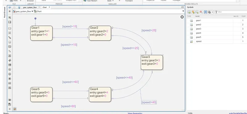
The blocks we need is given below:
- State flow chart
- Slider
- Constant
- Display
- Lamps
- Circular gauge.
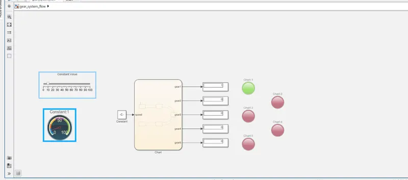
Result :
0 to 15 1st Gear
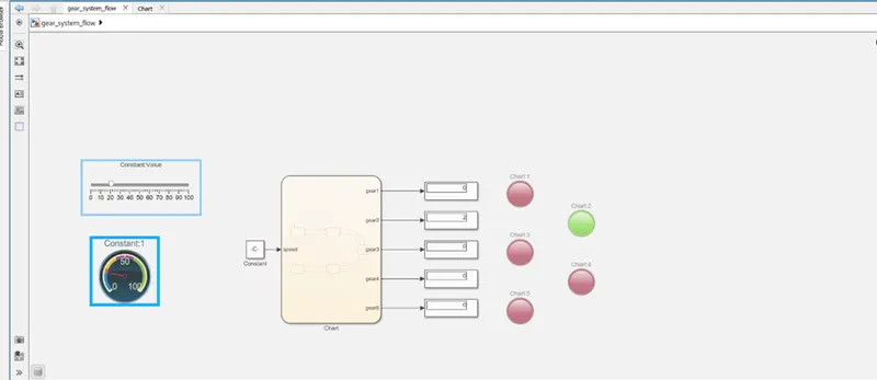
16 to 25 2nd Gear
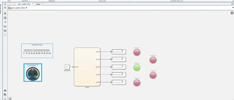
26 to 40 3rd Gear
41 to 60 4th Gear
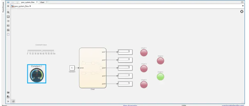
61 and above 5th Gear
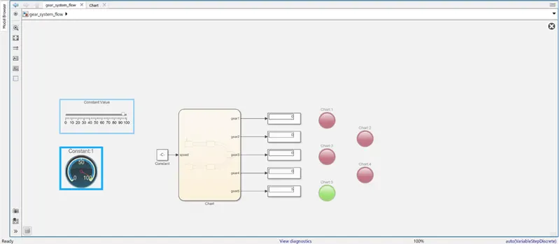
And therefore we successfully completed the gear shift logic and use of Simulink.
As we see lamb is glow according to according to gear and it shows . gear is at the current running according to the speed we selected from slider.