Week - 4
EV BATCH-17
1. Implement control logic of a “washing machine” using Stateflow as per given sequence:
- If the power supply is available, the system gets activated
- If the Water supply is not available, stop the process & indicate through LED
- Soaking time should be 200s followed by Washing time of 100s.
- Then rinsing happens for next 20s & dryer runs for 50s
After all the processes have completed turn on the finished LED
Aim:
To implement control logic of a “washing machine” using Stateflow by satisfying the below conditions
- If the power supply is available, the system gets activated
- If the Water supply is not available, stop the process & indicate through LED
- Soaking time should be 200s followed by Washing time of 100s.
- Then rinsing happens for next 20s & dryer runs for 50s
- After all the processes have completed turn on the finished LED
Blocks Used:
- Chart
- Constant
- Display
- Lamp (Indication)
Simulation Block:
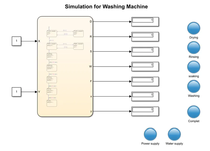
Explanation:
- Open the Blank model of simulink and then add the required blocks from library browser and make connections
- lets add the blocks in 'chart' block and made block designing according to our condition's and made connections of blocks. It is shown in below fig
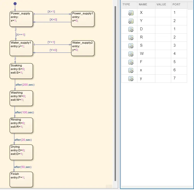
- And mentioned the used variables as which is the inputs and which is the output in model workplace
- Then connect the constant values as inputs of chart and Displays will connect to output terminals for showing the output values
- Then take the lamps for indication porpouse and that lamps to displays respectively
- Then run the simulation and observe the outputs and lamp indications
>> Here is the Washing machine ON condition & If the power supply is available, the system gets activated
all the lamps should indicate to ON state (Blue colour was Glowing). In this condition the power supply and water supply will be in ON State (1 value)
>> If the Water supply is not available, stop the process & indicate through LED:
In this condition, if water supply is available then the lamp LED will indicates the BLUE colour and if the water supply wiil not available then lamp LED will Indicates the RED colour then it will stop the process. it is showing below fig
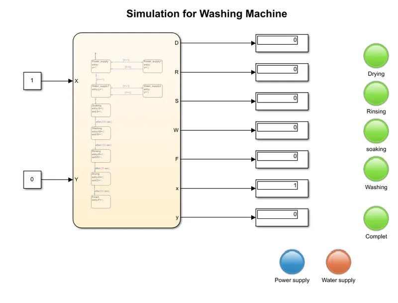
In this condition power supply will there but water supply will not there then the whole process will stoped
# Soaking time should be 200s
# Washing time of 100s.
# Then rinsing happens for next 20s
# Dryer runs for 50s
This all will mentioned in the Chart block only
----------------------------O-----------------------
2. Make a Simulink chart for the “Gear shift” logic as per below conditions:
Speed Range(kmph) Gear
0 to 15 1
16 to 25 2
26 to 40 3
41 to 60 4
Above 61 5
Give speed input while the simulation is running & display the gear number
Aim:
To
Make a Simulink chart for the “Gear shift” logic by Satisfiying Conditions and give speed input while the simulation is running & display the gear number.
Blocks Used:
- Chart
- Constant
- Slider
- Display
Simulation Block:
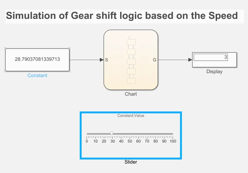
Explanation:
- Open the Blank model of simulink and then add the required blocks from library browser and make connections
- lets add the blocks in 'chart' block and made block designing according to our condition's and made connections of blocks. It is shown in below fig
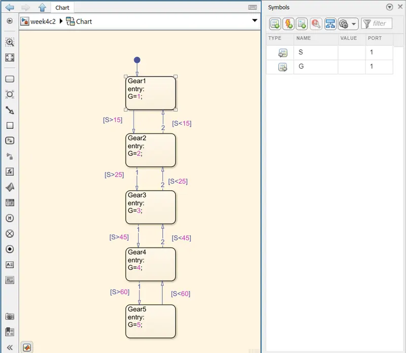
- And mentioned the used variables as which is the inputs and which is the output in model workplace
- Then connect the constant values as inputs of chart and Displays will connect to output terminals for showing the output values
- Then add the slider Block and conncet it to constant block. If the constant value will changes when slider will change the value then it will changes
- Then run the simulation and observe the results
Results:
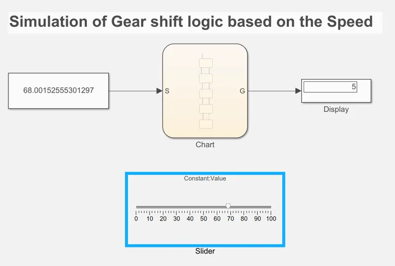
If the speed will changes then the Gear will automatically changes
>> 1st Gear
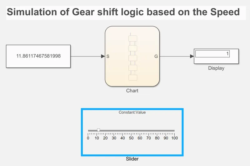
>> 2nd Gear
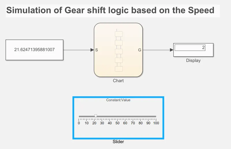
>> 3rd Gear
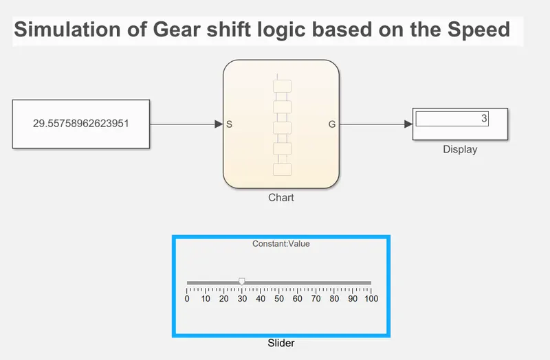
>> 4th Gear
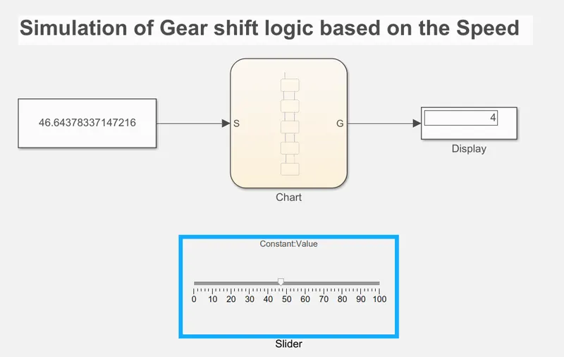
>> 5th Gear