Week - 4
QUESTION 1:
AIM:
To implement control logic of a "washing machine" using Stateflow in Simulink.
OBJECTIVES
The simulation has to follow certain condition according to which the machine shall work .We have to implement the control logic of a washing machine using stateflow as per given sequence:
- a) If the power supply is available, the system gets activated.
- b) If the Water supply is not available, stop the process & indicate through LED.
- c) Soaking time should be 200s followed by Washing time of 100s.
- d) Then rinsing happens for next 20s & dryer runs for 50s.
After all the processes have completed turn on the finished LED.
Simulink Model along with Explanation:-
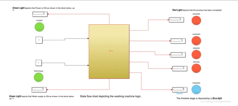
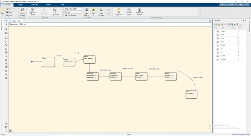
1.)As defined above the control logic of the washing machine is defined by certain condition and each condition has a definite time period for which it has to be performed each completed stage has been shown to the user with the help of LED Lamps.
2.)As the stage complets the lamp turns red and after all the stages are finished the lamp turns Blue depicting the Finished cycle.
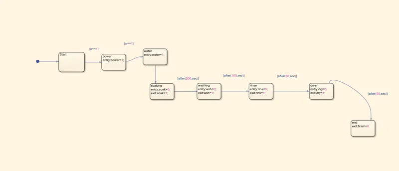
3.)In the above figure the control logic inside the state flow chart is shown the control is divide into time delays and the respective stage of washing cycle that are soaking, washing, rinsing,drying each onto with a designated time interval.
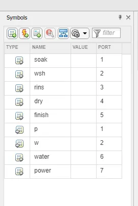
4.)The above depicts the symbols pane in the stae flow window that contains the input and output datas depicted by the box shape and the direction of the arrow symbol on the left of the data variables. Along with that the port numbers are also mentioned.
As we can observe from the above figure, All the states have been executed and indicating the Process completion indicator (named as Finished) showing Blue.
CONCLUSION:
- The simulation of the Washing machine using State flow is done and the result is satisfactory.
QUESTION 2:-
AIM:
To make a Simulink chart for the “Gear shift” logic.
OBJECTIVE:
Making a simulink chart for the Gear Shift for the below mentioned paramters:
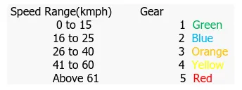
Speed Range(kmph) Gear
0 to 15 1
16 to 25 2
26 to 40 3
41 to 60 4
Above 61 5
Simulink Model with explanations:-
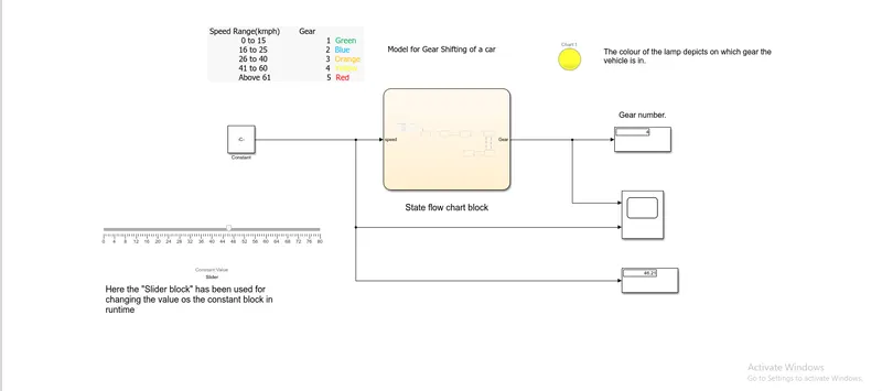
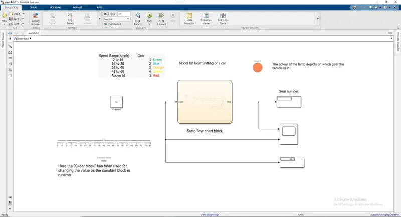
1.)The above figure represents the simulink model of a gear shift process in a car the condition for the gear shift to be on a particular gear no. has been given in the question for easy understanding colour codes(lamps with respective colours) have also been added so as to show in which gear the the car actually is.
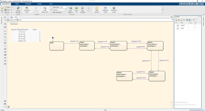
2.)The gear no. of the car is decide by the value of speed of the car the condition for that is given as an image below.
3.)The control logic of the gear shift model is defined in the state flow chart that has respective condition blocks for respective values of speed of the vehicle.The below given image shows the stae flow chart and the control logic.
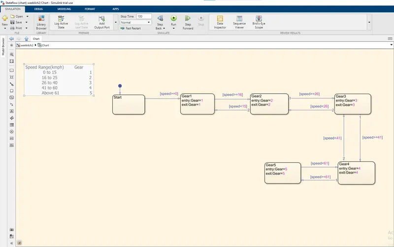
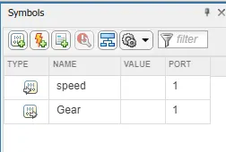 4.)This image depicts the input and output datas that can be clearly understood by the box and arrow icon on the left of the variable.
Conclusion:-
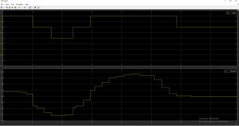
Looking at the above figure we can conclude that our simulated model is working fine as the display port depicts the speed to be 39.74 for which according to the given condition the gear shift value has to be 3 as depected correctly by the lamp color that shows Orange.Additional to that the graph showing the changing speed values alon with the gear value has also been provided.